Upstroke wing clapping in bats and bat-inspired robots improves both lift generation and power economy
Abstract
Wing articulation is critical for efficient flight of bird- and bat-sized animals. Inspired by the flight of Cynopterus brachyotis, the lesser short-nosed fruit bat, we built a two-degree-of-freedom flapping wing platform with variable wing folding capability. In late upstroke, the wings ”clap” and produce an air jet that significantly increases lift production, with a positive peak matched to that produced in downstroke. Though ventral clapping has been observed in avian flight, potential aerodynamic benefit of this behavior has yet to be rigorously assessed. We used multiple approaches – quasi-steady modeling, direct force/power measurement, and PIV experiments in a wind tunnel – to understand critical aspects of lift/power variation in relation to wing folding magnitude over Strouhal numbers between . While lift increases monotonically with folding amplitude in that range, power economy (ratio of lift/power) is more nuanced. At , it increase with wing folding amplitude monotonically. At , it features two maxima – one at medium folding amplitude (), and the other at maximum folding. These findings illuminate two strategies available to flapping wing animals and robots – symmetry-breaking lift augmentation and appendage-based jet propulsion.
1 Introduction
Bats fly with highly-articulated wings; in particular, the kinematics of the handwing, from the wrist to the wing tip, vary significantly with flight speed [1, 2, 3, 4, 5]. During upstroke, in addition to wing elevation, bats’ wrists flex, which rotates the handwing with respect to the armwing about a chord-wise axis through the wrist, and fold the wings [3] (Fig. 1A). It has been suggested that folding reduces the inertial power of wing elevation [6], and that the reduced wing wetted surface area due to folding leads to a decrease in negative lift [2, 3]. During late downstroke, due to wing folding, the additional angular velocity of the handwing increases its effective angle of attack and effective velocity, which contribute to greater lift [7, 8]. It is therefore no surprise that bio-inspired robotic flyers with wing folding capability also demonstrate superior performance, such as flight endurance [9, 10], compared to those that flap but do not fold [11]. 222Note that in this study, we employ a specific definition of wing folding: the additional rotation of the outboard wing section (handwing) relative to inboard wing section (armwing) in the stroke plane (Fig. 1B) [9, 10]. This differs from the planar protraction/retraction of wings along the wingspan [12], which has also been referred to as wing folding [13, 14, 15].
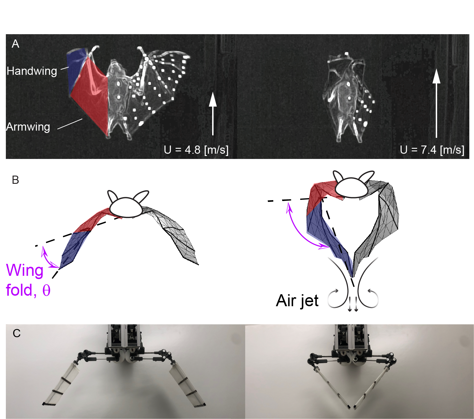
In some cases, bats fold their wings so much during upstroke [16], and the two wingtips touch and clap (Fig. 1B). This phenomenon occurs not only in multiple bat species [17, 18], but also in small birds that hover, such as Warbling White-eyes (Zosterops japonicus ), and Gouldian Finches (Erythrura gouldiae ) [19, 20].
In this manuscript, we report on efforts to understand how wing folding may influence flight performance in bats in terms of aerodynamics and energetics. This is difficult or impossible to ascertain in live animals, and thus we designed, built and tested a mechanical robot, “Flapperoo”, that abstracts key features of the bats’ wingbeat kinematics, allowing us to manipulate relevant variables.
By combining direct force/power measurements, time-resolved particle image velocimetry (PIV), and quasi-steady modeling, we explain the measured forces/power using validated blade-element momentum theories using the observed kinematics [4, 5]. Additionally, the measured forces, power and PIV help to determine the effectiveness and limitations of the reduced-order computational model. If folding enhances flight performance of membrane wings, an exploration of this enhancement using robotic platform is a crucial first step in the design process, which identifies how best to incorporate wing folding into a flapping wing engineered device.
However, there are as yet no systematic studies on the unique wing folding/clapping phenomenon. Few robotic studies have implemented the actively-actuated wing folding motion observed in bat and bird species [9, 21] and, to the best of our knowledge, none have reported the power and aerodynamics of varying wing fold amplitudes. Both Chen et al. [21] and Kashi et al. [22] built robotic flappers to replicate folding in wings or during flipper clapping, but no lift benefits were observed.
To assess the role of wing folding in flapping flight, both flapping and folding motions are programmable for Flapperoo. The bio-inspired robot allows direct measurement of force and power in a manner that is not possible from animals. The wing movement mechanism is composed of two four-bar linkages, driven by two servomotors, in which one controls wing flapping, a movement of the “armwing”, and the other controls wing folding, a movement of the “handwing” relative to the armwing (see Fig. 1C, Fig. 2A, and refer to Sec. 2 for more detailed description).
We define up- and downstroke by the motions of the armwing and set them to be equal in duration. Studies of hovering Japanese White-eyes, Zosterops japonicus, and Gouldian Finches, Erythrura gouldiae, have classified wing clapping as part of downstroke [19, 20], based on the trajectories the wing tips. However, the primary flight motor of vertebrates is the pectoralis major muscle [23], and for this reason, we deem the motion of armwing to be a more accurate reflection of up- vs. downstroke. Additionally, the cyclic motion of the armwing is more stable and consistent than that of the deforming handwing. Using this framework, bat wing clapping occurs after the armwing has reached the bottom of the downstroke and begun upstroke, although the handwings, which perform the clap, are still moving downward (ventrally) at this point in the wingbeat cycle. For all the wing folding cases we considered, folding begins in the late downstroke.
We carried out tests over a range of freestream velocities and wing folding amplitudes in a wind tunnel (Fig. 2B). This corresponded to Strouhal numbers, , (defined as , where is the flapping frequency, is the vertical wingtip displacement when there is no folding, and is the freestream velocity [24, 16]) over the range of - a particularly relevant range for flying animals [25]. We used the measured robot kinematics as input to a quasi-steady computational model [4, 8, 5], which estimated aerodynamic force and power. Then, we compared force and power, estimated from the computational simulations, with the directly measured forces (from a force transducer) and power consumption (from the motor’s driving current and voltage). To quantitatively characterize the air jet produced, we measured the flow in a vertical (parasaggital) plane between the two wings (Fig. 2B) using time-resolved, particle image velocimetry (PIV), and performed a Reynolds-averaged control volume analysis to assess the forces associated with this flow [26, 27].

2 Materials & Methods
We designed and built a two-degree-of-freedom (DoF) flapping wing robot, Flapperoo, capable of both wing flapping and folding. The flapping motion (red, Fig. 2A) is realized by a four-bar linkage mechanism. A crank rotates continuously in one direction to pull/push the ball link (coupler), causing the armwing (rocker) to oscillate up and down; the angle between the rocker and the horizontal plane is denoted as the flapping angle , which is fixed. To fold the handwing (blue, Fig. 2A), an independent crank is driven reciprocally, dragging the coupler to move in and out. This motion pivots the spur gear (planet gear, blue) on the rocker (carrier) to rotate against the fixed gear mounted on the armwing (sun gear, black), so that the folding angle is amplified ( ratio). The handwing is fixed to the spur gear, and the angle it makes relative to the armwing (black) is the wing folding angle, denoted as . The folding of wings begin at of a cycle, in the downstroke (black arrow in Fig. 4A2), and is sinusoidal. A streamlined body for Flapperoo was hand-sculpted using foam and houses the flapping mechanism (Fig. 2B). The body and wings were painted matte black to reduce light scattering during PIV experiments.
The wing ribs were laser-cut from flat balsa wood strips with a chord length of mm, and a thickness of mm. The equally-spaced ribs were glued onto a mm carbon-rod spar before being covered with rip-stop, kite-cloth fabric. The handwing and armwing are equal in length. The wing assembly weighs -grams. To isolate the effect of handwing structure, the mm armwing skeletal frame is not covered with fabric.
The flapping and folding movements are actuated by two brushless, rotary servomotors with integrated encoders (BE163CJ-NFON, Parker Hannifin Corp., Rohnert Park, CA), controlled by a servo controller (DMC-4060, Galil Motion Control, Rocklin, CA). The motors are controlled using custom written code in software developed for the controller (GDK, Galil Motion Control), and operate in ‘PVT’ mode, where the user defines a list of target positions and velocities at a series of defined times. The controller then moves the motor through a profile that reaches each target position at the target time, moving at the target velocity. The list of target values was calculated using a Matlab script.
The flapping motor was programmed to execute a constant speed rotation. We used a testing frequency of 3 Hz for all investigations reported here. The folding motor was programmed to start the fold motion at and to end at . Due to the coaxial nature of the rocker during flapping and the crank during folding, friction will cause one to rotate with the other, and thus, even for the no folding-case (), we drive folding at a low level to counter this friction at a non-zero amplitude (Fig. 4A1). This small base offset is added to all other cases.
The robot was tested in a closed-loop wind tunnel at Brown University [28] (Fig. 2B). The test section is meters in cross section and 4 meters long. We varied the freestream velocity to achieve the desired Strouhal number, , where is the vertical wingtip displacement when there is no folding (), and is the freestream velocity for the fixed 3 Hz testing frequency [24, 16]. We introduce an additional, local Strouhal number to describe jet scaling during wing clapping, , where is the length of each individual handwing.
The robot was mounted on a six-axis force/torque sensor (Gamma IP65, ATI Industrial Automation, NC) and force/torque measurements were recorded using an A/D converter (USB-6343, National Instrument, TX) at Hz. Angular velocity and torque were recorded at Hz from the motors using the Galil motion controller, and their inner product was computed to yield mechanical power. The net lift was normalized by the dynamic pressure of the freestream and the wing area: . The net power was similarly normalized by the dynamic pressure of the freestream and the wing area and chord as: .
For each trial, we first acquired data with the handwings attached, and then removed the handwings and repeated each measurement with the same set of parameters. The trials without handwings record the inertial forces and torques associated with motion of the mechanical components (e.g., gears, cranks, etc). Note that the inertia power from handwing () alone is negligible, and is thus not considered. A Butterworth low-pass filter was applied to these data with a cut-off frequency . The net aerodynamic force or power is the difference between these two conditions (see also Bahlman et al. [14]).
White reflective markers, placed at the leading edge of the wings, were tracked from video acquired by two Phantom Miro 340 cameras (Vision Research Inc.) at fps. The video and force data acquisition were synchronized using an Arduino microcontroller. The cameras were calibrated and and the video digitized using DLTdv8 [29]. Subsequently, the wing kinematics were used in a quasi-steady flapping flight model to predict aerodynamic force and power [12, 4, 8, 5].
The particle image velocimetry (PIV) experiment used a Nd:YLF double-pulsed laser (DM30, Photonics Industries, Ronkonkoma, NY), employed at Hz with an energy output of approximately mJ/pulse. The vertical laser sheet was aligned with the flow direction and passed through the Flapperoo’s body midline, the center of the gap between the wingtips (Fig. 2B). The test-section was seeded with neutrally buoyant, helium-filled soap bubbles (diameter 0.3 mm), released upstream of Flapperoo (Lavision Inc., Germany). The bubbles illuminated by the laser sheet were imaged by two high-speed cameras (Photron NOVA R2, 2048 x 2048 pixels), positioned side by side with overlapping fields of view, producing a combined field of view of mm. We used DaVis PIV software v10 (LaVision Inc., Germany) to perform image cross-correlation, and MATLAB code to obtain time-resolved phase-averaged velocity fields in and ( bins/cycle, where each bin contained repetitions [30]).
The aerodynamic forces that result from wing clapping, , were derived from the Navier-Stokes equation using the control volume (C.V.) analysis approach (Fig. 4C, see Bohl et al. [26] for a similar but simpler analysis):
| (1) |
where is the air density, the velocity field of the flow, the surface normal of each control surface (C.S.), and the pressure acting on each surface.
All derivatives were evaluated using a Savitzky–Golay filter (order 2, frame length 5) [31]. The first term is a volume integral of the acceleration field along the vertical direction, the second term is the transport of axis momentum across each downstream boundary surfaces of the control volume, and the third term is a line integral that gives the pressure difference between bottom () and top () surface in Fig. 4C.
To obtain the clapping lift coefficient , we assume that the width of the jet is uniform into the depth of the measurement plane (-axis in Fig. 2B) around the time of wing clapping, and that the width is of the order of twice the length of the handwing, , consistent with PIV studies of wing clapping in birds [19, 20]. Normalized by the dynamic pressure, , and surface area of the whole wing, , the lift coefficient from the PIV experiment is thus .
3 Results
3.1 Robot performance
We present results for two cases at the extreme of the robot’s kinematic space: near-zero wing folding, , and extreme wing folding with a wing clap (Fig. 3). For both cases the freestream m/s, which corresponds to .
We observed smooth flapping motion that followed the prescribed motion with reasonable fidelity (Fig. 4A1 and A2, green lines). For the near-zero prescribed folding angle case (Fig. 4A1), the folding angle of the handwing varies passively over the wingbeat cycle, with values ranging from to . The observed folding angle is closer to the prescribed value for the larger folding angle case, with values similar to those prescribed in magnitude but with a phase lag of about (Fig. 4A2). See also the hand wing total angles with respect to mid-stroke plane in supplementary Fig. S7.
3.2 Lift
The mechanics and energetics of the two folding cases differ substantially. The magnitude and trend of the aerodynamic lift coefficient, (, where is the dimensional force, is the fluid density, and is the total area of the two handwings), for the case of near-zero folding is similar when measured by the force transducer (FT) and predicted by our quasi-steady model, [4, 5] (Fig. 4A3). Positive lift is generated during downstroke, and negative lift during upstroke. The quasi-steady model diverges from the FT data primarily by an overprediction (more positive lift) of in late downstroke/early upstroke (), and an underprediction (less positive lift) around the upstroke to downstroke reversal (). For the extreme wing folding case (Fig. 4A4), downstroke is responsible for most of the positive lift (), but there is more variation across the wingbeat cycle and a more pronounced difference between the lift estimates of the measurement and the quasi-steady model . Specifically, the model produces a more pronounced underprediction of in comparison to the FT measurement at the beginning of downstroke (snapshot i), and slightly overpredicts lift around the mid-downstroke (between snapshots i and ii). The quasi-steady and FT measurement agree well late in downstroke (snapshot ii). At time , when the wing claps (Fig. 4A4, snapshot iii), the quasi-steady model fails to predict the peak in lift generation in Fig. 4A4. Towards the end of upstroke (, Fig. 4A4, snapshot iv) when the wing has completed the upstroke movement from the ventral to the dorsal side of the body and prepares for the next downstroke, the quasi-steady model captures the negative lift measured by the force transducer, albeit with a slight overprediction and phase delay.
3.3 Power Consumption
Computations of the quasi-steady model predict moderate peaks in power consumption during the middle of the downstroke and the upstroke (Fig. 4A5). These predictions are supported by the power measurements from the robot, although there is a delay (with the quasi-steady model leading by ) in the power maximum. When wing folding is at its maximum (, Fig. 4A6), the model predicts a more complex time course for power consumption, but the overall pattern of power use measured from Flapperoo is a close match to the simulation, with the exception of an underprediction of power at snapshot iii (), and a sharp rise in predicted power late in the upstroke at , (snapshot iv) which is not observed by the measurement.
3.4 Velocity field
PIV measurements of the flow field along the midline plane of Flapperoo show a prominent jet that is directed downward and to the rear of the “animal”, which appears as a result of wing clapping at , (snapshot iii, and Fig. 4B). Because the velocity measurement is restricted to the centerline plane between the two wings, the control volume (CV) analysis of the aerodynamic forces associated with this jet (Fig. 4A4 - blue line), are only expected to yield accurate force estimates during the portion of the wingbeat cycle in which wing clapping occurs (refer to sec. 2 for a more detailed description). During this time period, agrees well with FT measurement. During other portions of the wingbeat cycle, flow in this plane closely follows the freestream and = 0 (see video in supplementary S1). The calculated from the CV approach is independent of the CV boundary (once a large enough volume is chosen).
The jet is produced as a result of left and right wings clapping, “squeezing” air out. We predict that the strength of the jet created by two wings clapping will depend on the distance between the wingtips, which, in turn, depends on the clapping amplitude, ) and the speed of the approaching wings, , where is the flapping frequency and is the length of the handwing, measured from the wrist to the wingtip. We define a local lift coefficient, , from the peak lift force during the clap (Fig 4A4), and observe a clear dependence of on clapping amplitude, , and the wingtip velocity (normalized by the flight speed to form a clapping Strouhal number: )(Fig 4C).

Wing folding confers aerodynamic benefits but requires actuation, and so incurs energetic costs. Examination of the cycle-averaged lift coefficient, , and power economy (the ratio of to ) as a function of Strouhal number, (Fig. 5A) shows that for the non-folding case, , the cycle-averaged is close to zero for all values of (the upstroke-downstroke wing motion is symmetric when wing folding amplitude, , is non-zero, and hence no net lift is expected). With wing folding, the cycle-averaged lift coefficient increases with , up to a maximum value of for . For a given Strouhal number the lift coefficient increases with wing folding amplitude, , and increases more steeply close to the clapping condition (see supplementary Fig. S4, for to ).
Power economy, , does not monotonically increase with fold angle nor fold angle (Fig. 5B and Fig. 6). For low to moderate ( - moderate to fast flight), power economy increases monotonically with folding amplitude and peaks at the highest fold angle . For higher ( - lower flight speed), the most economical solution to gain lift occurs around , although Power economy does start to increase again due to wing clapping at high folding amplitude (Fig. 6). Thus at high , power economy features twin peaks, one at moderate folding, and the other at extreme folding amplitude. Note that right around , both folding angle of and are indistinguishably optimal.
4 Discussion
Generation of propulsion by jetting for locomotion is well-known in the biological world. Jellyfish contract circular muscle fibers in their hemispherical bell-shaped bodies, shrinking total volume and ejecting water to effect the jet [32]. Circular muscles around the squid funnel of the squid mantle cavity control intake and propulsive outflow of water [33]. The vortex dynamics of these volume reduction-based approaches to jet propulsion have received considerable attention in the fluid dynamics community. Similarly, appendages can generate jet propulsion. Sea Lions clap their rear flippers during swimming [34], and wing clapping has been observed in small birds during hovering [19] and by some bats during fast flight [16, 5].
In addition to Cynopterus brachyotis , the inspiration for this study, biologists have long observed wing clapping behavior in bat species from the family Pteropodidae: Eonycteris spelaea, Macroglossus sobrinus, Eidolon helvum, and species in the genus Rousettus [17, 18]. The foci of these reports, however, were the clicking sounds generated by wing clapping as a form of biosonar [17, 18] and not any potential aerodynamic effects.
A robotic platform that mimics sea lion flippers demonstrated clapping-based jet propulsion but did not show force augmentation associated with the jet [22]. In contrast, we find that lift is significantly enhanced by wing clapping, with clapping generating a force close to that generated during the downstroke (snapshot iii in Fig. 4A4, and Fig. 3). This enhancement comes primarily during the upstroke, not generally considered a lift-generating phase of the wingbeat cycle [35, 2, 36].
4.1 Force estimates from PIV
To calculate the lift generated by wing clapping by hovering birds, Chang et al. [19, 20] conducted frontal and parasagittal plane PIV measurements during hovering flight of these birds, and a coherent vortex ring is visible as a result of ventral wing clapping. Lift is estimated from the circulation of this vortex ring during downstroke, under the assumption of an aerodynamically passive upstroke, and explains approximately of weight support. Here, we do not assume a vortex ring structure, but apply a control volume (CV) approach, which lends itself well to the spatially and temporally complex flow in terms of pressure, momentum flux, and acceleration of fluid by the wing motion.
By phase-averaging the flow field over wingbeat cycles, we found that the contribution from turbulent velocity fluctuations (see Supp. Mat.) is negligible in estimating compared to the mean (phase-averaged) values, suggesting that a coherent vortex ring dominates lift production. This agrees with the observation by Chang et al.[19, 20].
Net pressure and fluid acceleration start to build well before the wings clap (Fig. S1), suggesting that the wing-wing interaction occurs much earlier than the actual instant of clapping (see also [37]), and lasts a substantial fraction of a wingbeat ( in Fig. S1). Indeed, the wings do not need to be physically touching to effect the jet, but instead can be separated by a small distance (Fig. 4C).
4.2 Effectiveness and limitations of the quasi-steady model
For the case without wing folding (near-zero case), the agreement between the force measurements and the quasi-steady predictions is generally very good, both in terms of the overall trend and the magnitude of the lift force (Fig. 4A3). Because the the wing motion – up- and downstroke – is symmetric (Fig. 4A1), the model predicts the upstroke and downstroke forces to be equal and opposite, and the measurements largely support this – with the deviation due to slight asymmetry in the realized kinematics. Measured and predicted forces differ just ahead of the down- and upstroke reversals, at and respectively. At mid downstroke and upstroke ( and ), the velocity and effective angle of attack (eAoA) peak (supplementary Fig. S3A). As a result, the lift force peaks at these points in the cycle. The wing slows as it reaches stroke reversal, and the lift force predicted by the quasi-steady analysis approach zero. However, the measured lift drops to zero somewhat earlier in the wingbeat cycle.
This discrepancy between measured and predicted lift exposes one of the key weaknesses of the quasi-steady approach: it fails to account for the wake capture around the up- to downstroke reversal. At the end of downstroke, a leading edge vortex (LEV) forms on the dorsal side of the wing, [38, 39, 40]. This vortex contributes additional lift and, as long as it stays attached, can be modelled accurately by the quasi-steady approach using a generalized lift coefficient [41]. However, for large effective angles of attack, the vortex separates and when it moves away from the wing, the lift force drops precipitously. Simulations of vortex formation and shedding of a 2D airfoil have shown that for eAoA = 72∘, the vortex is much stronger and sheds more quickly than for the case of eAoA = 4.5∘, in which the core is weaker and remains attached [42]. Here, the eAoA at the 3/4-span section for the zero folding case () varies between -40 to 40 degrees (SFig. S3A). We suggest that at these points in the wingbeat cycle the LEV is likely shed into the wake, leading to the early drop in the lift coefficient, which is not captured by the low-order model.
For the case of 100∘ wing folding, the amplitudes of the forces are accurately captured and the overall trends match well, but we do see significant differences between measurements and the model predictions (Fig. 4A4). In particular, at the start of the downstroke (), at the beginning of the upstroke (), and lastly mid-upstroke (). The first two of these points in the cycle can be explained using the same reasoning as with the straight wing. In this case, the cycle of the effective angle of attack of the wing, and its return to zero is delayed due to the kinematics of wing folding (supplementary Fig. S3B), and the eAoA is high () at the stroke reversals () and does not drop to zero until and 0.7 respectively. As before, the quasi-steady analysis predicts zero lift when the eAoA is zero (as it should), while the measurements show that the lift has already dropped to zero ahead of the zero eAoA point due to the LEV separation.
At , during the upstroke of the high folding case, , the wings are almost perpendicular to the ground (Fig. 3),leading to a near zero prediction of from the quasi-steady model. The direct force measurement demonstrates a negative trough at this time, which may be due to the LEV on the dorsal side of the wing that generates unfavorable (negative) lift as it separates into the wake. However, shortly after this, at (stage iii in Fig. 3), while the model still predicts negligible lift due to the vertical orientation of the wing surfaces (Fig 3), the force measurements record a positive lift peak, also captured by the PIV measurements. This lift augmentation arises from wing clapping(Fig. 4B), as a brief jet of air is squeezed downwards, similar to jetting in swimming jellyfish or squid [32]. This momentary rise of due to wing clapping is not captured by the quasi-steady analysis, which cannot incorporate wing-wing interactions. The wing motors must provide extra energy to produce the jet and this additional power requirement is also absent from the quasi-steady model (Fig. 4A6, , see also snapshot iii in Fig. 3).
4.3 Aerodynamic force, power and efficiency of wing folding
Birds and bats adjust wing folding amplitude with flight speed [3, 43, 6]. But among diverse robotic flyers, few studies have implemented wing folding [9, 10, 44, 21, 44]. Of these, Wissa et al. [10] employed passive mechanisms, while Send et al. [9] implemented active wing folding with fixed amplitude and timing. Chen et al. [21] used a string-based approach to actuate variable-amplitude wing folding and found that wing folding helps reduce negative lift during upstroke in hovering condition. Through PIV measurements along the streamwise center plane of their robots, they demonstrated that the folded wings in upstroke are free of the impact of low pressure region under the wings, which otherwise would contribute to more negative lift.
Without wing folding (), the positive lift generated during the downstroke is balanced by the negative lift produced during the upstroke (Fig. 5A). For a given Strouhal number, , as wing folding,, increases, we observe two benefits. First, handwing effective velocity increases because of the additional rotation with respect to the armwing, and this enhanced velocity increases the local effective angle of attack. As a result, both factors can contribute to greater lift (snapshot ii, Fig. 4A4 and Fig. 3). Second, the effective wing surface area is reduced during upstroke, which alleviates negative lift, as has also been demonstrated in CFD simulations [45]. The additive effect of these factors results in net positive cycle-averaged lift, , that increases with the folding amplitude, , (Fig. 5A).
We observe a qualitatively distinct phenomenon when wing folding amplitude exceeds a certain threshold (see schematics in Fig. 4C). The handwing lags the armwing, and when the armwing transitions from down- to upstroke, the handwing continues through its ‘downstroke’ trajectory. The two wingtips move toward one another as they approach the midline, in a manner that can be described heuristically as “scooping” the air, producing a trough of negative lift (Fig. 4A4, between snapshots ii and iii). This phenomenon is also observed in small hovering birds [19, 20].
As the handwings approach and ultimately clap (Fig. 4B), air is propelled dorsally and ventrally from the small gap between the wings (Fig. 4C). The net effect is a downward, ventral, momentum jet that produces positive lift, comparable in magnitude to that generated during downstroke (Fig. 4A4). In contrast, when Gouldian Finches clap, they position their wings to prevent dorsally-directed air movement [20]).
The wingtips separate after the clap and are re-positioned prior to the next downstroke (snapshot iv, Fig. 4A4). With no modification of the movement, this preparatory movement could incur a substantial negative lift penalty, however, birds and bats adopt similar mitigation strategies. In both groups, the handwing supinates (rotates about the spanwise, long axis in the palm-upward direction) at the wrist and the wing retracts along the span by flexion at the elbow. The posture of the handwing may come close to a vertical plane before moving dorsally – as it “slices” through air – during the upstroke [46, 4, 2, 7]. Upstroke kinematics of bats and birds reduce negative lift [19, 39, 2] and generate a small amount of thrust [36, 47]. The wings of Flapperoo presented in this manuscript can neither twist nor retract, and the resulting unfavorable orientation of wing surfaces during rapid upstrokes leads to substantial negative lift. However, we did then designed, built and tested a Flapperoo with twisting capability, and found that twisting significantly decreased both power consumption, and negative lift during upstroke (accepted to present in IROS 2024, arXiv link [48]).
In summary, two different mechanism to obtain optimal efficiency, characterized by power economy, are displayed here, and we may classify them as symmetry-breaking lift augmentation (small folding amplitude ) and appendage-based jet propulsion (extreme folding amplitude ). At low speed or high (Fig. 5B), it takes extra effort to actuate large wing folding to effect air jet for extra lift, thus the symmetry-breaking strategy (moderate folding amplitude ) is more cost effective, in terms of ; on the other hand, for fast flight speed or low , while symmetry-breaking strategy is still rewarding, jet propulsion with large folding angle becomes much more efficient (Fig. 6). It is remarkable to note that flapping wing flight has both strategies at its disposal.
4.4 Similarities and differences with “clap-and-fling”
The characteristic “clap-and-fling” mechanism of insects and slowly flying birds [49, 37, 50] relies on the two wings coming together during the wingbeat cycle, but it differs fundamentally from the ventral clapping motion considered here. In clap-and-fling, the ‘fling’ part of the motion generates thrust and enhances lift by augmenting circulation around the wing during early downstroke on the dorsal side [37]. The ventral clapping mechanism that we describe here generates lift during upstroke by producing a directed jet of air.
In both clap-and-fling and ventral wing clapping, however, negative lift is produced as a result of an upward jet, which can persist before and during the clapping ( of case , Fig. 4A4) [20, 37], Fig. 4B). The magnitude of net lift increase for insects, due to clap-and-fling, is small (Fig. 4 in [37]), whereas we observe a more substantial boost, with a peak in the clapping-derived lift force comparable to that generated during the downstroke. This distinction might be due to differences in the swept area. In clap-and-fling, the wings simultaneously rotate and translate (panel M-P in Fig. 7 in [37]) so that the leading edge of the wings meet first, subsequently ”squeezing” air out at the trailing edge. However, the volume of air trapped during this motion is much less than that the corresponding volume of air trapped by Flapperoo, where the armwings never come close and the handwings are on opposite sides of the relatively large body.
4.5 Guidelines for flapping wing robots
The potential benefits of ventral wing clapping, as demonstrated here, may inform future design of flapping wing robots with high payload or endurance requirements. Wing folding in birds and bats is implemented primarily by flexion and extension at the wrist joint [51, 52].
Even though a passively wrist joint with well-tuned stiffness to a specific speed may achieve beneficial folding angles, the flight efficiency may not adapt to the speed changes.For example, the cycle-averaged power consumption of one passively deforming, bird-inspired ornithopter, Park Hawk [53], was approximately , which is considerably higher than the power requirement reported for SmartBird, a seagull-inspired robot that performs active wing folding and twist [9, 10], even though SmartBird has a greater wingspan and weighs more than Park Hawk. Here, we find that the cycle-averaged lift increases monotonically with wing folding angle across (Fig. 5A). This translates directly to the capacity to carry larger payloads, and suggests that the energetic penalty for actuating the wing folding motion provides an effective compromise between generating lift and energetic cost (Fig. 5B).
The controlled, selective variation in wing folding angles with flight speed by birds and bats [3, 5, 43], suggests that a flexible capability to modulate lift generation relative to energetic cost confers performance benefits. Adjustable folding angle could be incorporated in future designs for flapping wing robots to enhance their performance. For example, when agility is important, such as when navigating through a tight turn, an instantaneous boost of lift conferred by wing clapping might provide additional benefits with little impact on overall energetics due to the brief and temporary increase in power consumption. Moreover, ventral clapping is observed during fast flight ( m/s or ~ [5]) in Cynopterus brachyotis, where larger thrust is likely required to overcome high drag.
Indeed, the next generation of Flapperoo is also able to perform wing twists [48], and demonstrates the air jet due to ventral wing clapping, as discussed in this paper, can be directed wing angling at the moment of clap, where the leading edge almost touch but the trailing edge positioned slightly apart. This angled clapping produce streamwise propulsion (thrust) in addition to lift. This novel appendage-based propulsion offers many great opportunities to further probe into the optimal wing kinematics involving highly unsteady vortex dynamics, and also offers new control authority in both lift and thrust directions.
References
- Muijre F.T. et al. [2006] Muijre F.T., Johansson L.C., Barfield R., Wolf M., Spedding G.R., and Hedenstrom A. Leading-Edge Vortex Improves Lift in Slow-Flying Bats. Science, 319:1250, 2006.
- Hubel et al. [2010] T Y Hubel, D K Riskin, S M Swartz, and K S Breuer. Wake structure and wing kinematics: the flight of the lesser dog-faced fruit bat, Cynopterus brachyotis. Journal of Experimental Biology, 213(20):3427–3440, 2010. ISSN 0022-0949. doi: 10.1242/jeb.043257. URL http://jeb.biologists.org/cgi/doi/10.1242/jeb.043257.
- Hubel et al. [2016] Tatjana Y Hubel, Nickolay I Hristov, Sharon M Swartz, and Kenneth S Breuer. Wake structure and kinematics in two insectivorous bats. Philosophical Transactions of the Royal Society B: Biological Sciences, 371(1704):20150385, 2016. ISSN 0962-8436. doi: 10.1098/rstb.2015.0385. URL http://dx.doi.org/10.1098/rstb.2015.0385%5Cnhttp://rstb.royalsocietypublishing.org/lookup/doi/10.1098/rstb.2015.0385.
- Fan and Breuer [2021a] Xiaozhou Fan and Kenneth Breuer. Low-Order Modeling of Flapping Flight with Highly Articulated, Cambered, Heavy Wings. AIAA Journal, pages 1–10, 2021a.
- Fan et al. [2022] Xiaozhou Fan, Sharon Swartz, and Kenneth Breuer. Power requirements for bat-inspired flapping flight with heavy, highly articulated and cambered wings. Journal of the Royal Society, Interface, 19(194):20220315, 2022. ISSN 17425662. doi: 10.1098/rsif.2022.0315.
- Riskin et al. [2012] Daniel K Riskin, Attila Bergou, Kenneth S Breuer, and Sharon M Swartz. Upstroke wing flexion and the inertial cost of bat flight. Proceedings of the Royal Society B: Biological Sciences, 279(1740):2945–2950, 2012. ISSN 14712954. doi: 10.1098/rspb.2012.0346.
- Sekhar et al. [2018] Susheel Sekhar, Peter Windes, Xiaozhou Fan, and Danesh K. Tafti. Canonical description of wing kinematics and dynamics for a straight flying insectivorous bat (Hipposideros pratti). PLoS ONE, 14(6), 2018. ISSN 19326203. doi: 10.1371/journal.pone.0218672.
- Fan et al. [2021] Xiaozhou Fan, Kenneth Breuer, and Hamid Vejdani. Wing Fold and Twist Greatly Improves Flight Efficiency for Bat-Scale Flapping Wing Robots. In IEEE International Conference on Intelligent Robots and Systems, 2021.
- Send et al. [2012] Wolfgang Send, Markus Fischer, Kristof Jebens, Rainer Mugrauer, Agalya Nagarathinam, and Felix Scharstein. Artificial hinged-wing bird with active torsion and partially linear kinematics. In 28th Congress of the International Council of the Aeronautical Sciences, pages 23–28. Optimage Ltd. on behalf of the International Council of the Aeronautical Sciences, Edinburgh, 2012, 2012.
- Wissa et al. [2012] A. A. Wissa, Y. Tummala, J. E. Hubbard, and M. I. Frecker. Passively morphing ornithopter wings constructed using a novel compliant spine: Design and testing. Smart Materials and Structures, 21(9), 2012. ISSN 09641726. doi: 10.1088/0964-1726/21/9/094028.
- Bie et al. [2021] Dawei Bie, Daochun Li, Jinwu Xiang, Huadong Li, Zi Kan, and Yi Sun. Design, aerodynamic analysis and test flight of a bat-inspired tailless flapping wing unmanned aerial vehicle. Aerospace Science and Technology, 112:106557, 2021. ISSN 12709638. doi: 10.1016/j.ast.2021.106557. URL https://doi.org/10.1016/j.ast.2021.106557.
- Vejdani et al. [2019] Hamid R. Vejdani, David B. Boerma, Sharon M. Swartz, and Kenneth S. Breuer. The dynamics of hovering flight in hummingbirds, insects and bats with implications for aerial robotics. Bioinspiration and Biomimetics, 14(1), 2019. ISSN 17483190. doi: 10.1088/1748-3190/aaea56.
- Bahlman et al. [2013] Joseph W Bahlman, Sharon M Swartz, and Kenneth S Breuer. Design and characterization of a multi-articulated robotic bat wing. Bioinspiration & Biomimetics, 8(1):16009, 2013. ISSN 1748-3182. doi: 10.1088/1748-3182/8/1/016009. URL http://stacks.iop.org/1748-3190/8/i=1/a=016009?key=crossref.efb4a846e3c87af350683c49f67e170d.
- Bahlman et al. [2014] Joseph W Bahlman, Sharon M Swartz, and Kenneth S Breuer. How wing kinematics affect power requirements and aerodynamic force production in a robotic bat wing. Bioinspiration & Biomimetics, 9(2):25008, 2014. ISSN 1748-3182. doi: 10.1088/1748-3182/9/2/025008. URL http://stacks.iop.org/1748-3190/9/i=2/a=025008?key=crossref.f715ef479820d90dfc7c1c265e3e9e29.
- Stowers and Lentink [2015] Amanda K Stowers and David Lentink. Folding in and out: passive morphing in flapping wings. Bioinspiration & Biomimetics, 10(2):025001, 2015. ISSN 1748-3190. doi: 10.1088/1748-3190/10/2/025001. URL http://stacks.iop.org/1748-3190/10/i=2/a=025001?key=crossref.a8a11ecfbeb3c732dbd277e7e5d44c11.
- Riskin et al. [2008] Daniel K. Riskin, David J. Willis, Jose Iriarte-Diaz, Tyson L. Hedrick, Mykhaylo Kostandov, Jian Chen, David H. Laidlaw, Kenneth S. Breuer, and Sharon M. Swartz. Quantifying the complexity of bat wing kinematics. Journal of Theoretical Biology, 254(3):604–615, 2008. ISSN 00225193. doi: 10.1016/j.jtbi.2008.06.011.
- Gould [1988] Edwin Gould. WING-CLAPPING SOUNDS OF EONYCTERIS SPELAEA (PTEROPODIDAE) IN MALAYSIA. JOURNAL OF MAMMALOGY, 69(2):378–379, 1988.
- Boonman et al. [2014] Arjan Boonman, Sara Bumrungsri, and Yossi Yovel. Nonecholocating fruit bats produce biosonar clicks with their wings. Current Biology, 24(24):2962–2967, 2014. ISSN 18790445. doi: 10.1016/j.cub.2014.10.077. URL http://dx.doi.org/10.1016/j.cub.2014.10.077.
- Chang et al. [2011] Yu Hung Chang, Shang Chieh Ting, Chieh Cheng Liu, Jing Tang Yang, and Chyi Yeou Soong. An unconventional mechanism of lift production during the downstroke in a hovering bird (Zosterops japonicus). Experiments in Fluids, 51(5):1231–1243, 2011. ISSN 07234864. doi: 10.1007/s00348-011-1145-8.
- Chang et al. [2013] Yu Hung Chang, Shang Chieh Ting, Jian Yuan Su, Chyi Yeou Soong, and Jing Tang Yang. Ventral-clap modes of hovering passerines. Physical Review E - Statistical, Nonlinear, and Soft Matter Physics, 87(2):1–11, 2013. ISSN 15502376. doi: 10.1103/PhysRevE.87.022707.
- Chen and Yeh [2021] Wei Han Chen and Szu I. Yeh. Aerodynamic effects on an emulated hovering passerine with different wing-folding amplitudes. Bioinspiration and Biomimetics, 16(4), 2021. ISSN 17483190. doi: 10.1088/1748-3190/abf6b8.
- Kashi et al. [2020] Elijah Kashi, Aditya A. Kulkarni, Gino Perrotta, and Megan C. Leftwich. Flowfields produced by a robotic sea lion foreflipper starting from rest. Bioinspiration and Biomimetics, 15(3), 2020. ISSN 17483190. doi: 10.1088/1748-3190/ab6a62.
- Vaughan [1959] T A Vaughan. Functional morphology of three bats:£Eumops, Myotis and Macrotus£. Univ. Kansas Sci. Bull., 12/1:1–153, 1959.
- Taylor and Thomas [2003] Graham K. Taylor and Adrian L.R. R Thomas. Dynamic flight stability in the desert locust Schistocerca gregaria. Journal of Experimental Biology, 206(16):2803–2829, 2003. ISSN 00220949. doi: 10.1242/jeb.00501.
- Taylor et al. [2003] Graham K Taylor, Robert L Nudds, and Adrian L.R. Thomas. Flying and swimming animals cruise at a Strouhal number tuned for high power efficiency. Nature, 425(6959):707–711, 2003. ISSN 00280836. doi: 10.1038/nature02000.
- Bohl and Koochesfahani [2009] Douglas G. Bohl and Manoochehr M. Koochesfahani. MTV measurements of the vortical field in the wake of an airfoil oscillating at high reduced frequency. Journal of Fluid Mechanics, 620:63–88, 2009. ISSN 14697645. doi: 10.1017/S0022112008004734.
- Mathai et al. [2023] Varghese Mathai, Asimanshu Das, Dante L. Naylor, and Kenneth S. Breuer. Shape-Morphing Dynamics of Soft Compliant Membranes for Drag and Turbulence Modulation. Physical Review Letters, 131(11):114003, 2023. ISSN 10797114. doi: 10.1103/PhysRevLett.131.114003. URL https://doi.org/10.1103/PhysRevLett.131.114003.
- Breuer et al. [2022] Kenneth Breuer, Mark Drela, Xiaozhou Fan, and Matteo Di Luca. Design and performance of an ultra-compact low-speed low-turbulence level wind tunnel for aerodynamic and animal flight experiments. Experiments in Fluids, 2022. ISSN 14321114. doi: 10.2514/6.2020-3107. URL https://doi.org/10.1007/s00348-022-03519-1.
- Hedrick [2008] Tyson L. Hedrick. Software techniques for two- and three-dimensional kinematic measurements of biological and biomimetic systems. Bioinspiration and Biomimetics, 3(3), 2008. ISSN 17483182. doi: 10.1088/1748-3182/3/3/034001.
- Onoue and Breuer [2016] Kyohei Onoue and Kenneth S. Breuer. Vortex formation and shedding from a cyber-physical pitching plate. Journal of Fluid Mechanics, 793:229–247, 4 2016. ISSN 14697645. doi: 10.1017/jfm.2016.134.
- Savitzky and Golay [1964] Abraham Savitzky and E. M. J. Golay. Smoothing and Differentiation of Data by Simplified Least Squares Procedures. Analytical Chemstry, 40(2):1832, 1964. URL https://pubs.acs.org/sharingguidelines.
- Costello et al. [2020] John H Costello, Sean P Colin, John O Dabiri, Brad J Gemmell, Kelsey N Lucas, and Kelly R Sutherland. The Hydrodynamics of Jellyfish Swimming. Annual Review of Marine Science, 2020. doi: 10.1146/annurev-marine-031120. URL https://doi.org/10.1146/annurev-marine-031120-.
- Anderson and Demont [2000] Erik Anderson and Edwin Demont. Squid swim using a jet propulsion system and undulating fins. The Journal of Experimental Biology, 2000.
- Perrotta et al. [2022] Gino Perrotta, Frank E. Fish, Danielle S. Adams, Ariel M. Leahy, Abigal M. Downs, and Megan C. Leftwich. Velocity Field Measurements of the California Sea Lion Propulsive Stroke Using Bubble PIV. Fluids, 7(1), 2022. ISSN 23115521. doi: 10.3390/fluids7010003.
- Shyy et al. [2013] Wei Shyy, Hikaru Aono, Chang-Kwon Kang, and Hao Liu. An Introduction to Flapping Wing Aerodynamics. Cambridge University Press, 2013. doi: 10.1017/cbo9781139583916.
- Hedenström et al. [2007] A. Hedenström, L. C. Johansson, M. Wolf, R. Von Busse, Y. Winter, and G. R. Spedding. Bat flight generates complex aerodynamic tracks. Science, 316(5826):894–897, 2007. ISSN 00368075. doi: 10.1126/science.1142281. URL http://www.sciencemag.org/cgi/doi/10.1126/science.1142281.
- Lehmann et al. [2005] Fritz Olaf Lehmann, Sanjay P. Sane, and Michael Dickinson. The aerodynamic effects of wing-wing interaction in flapping insect wings. Journal of Experimental Biology, 208(16):3075–3092, 2005. ISSN 00220949. doi: 10.1242/jeb.01744.
- Sane and Dickinson [2002] Sanjay P Sane and Michael H Dickinson. The aerodynamic effects of wing rotation and a revised quasi-steady model of flapping flight. The Journal of experimental biology, 205(Pt 8):1087–1096, 2002. ISSN 0022-0949. doi: 10.1126/science.167.3915.177.
- Windes et al. [2018] Peter Windes, Xiaozhou Fan, Matt Bender, Danesh K Tafti, and Rolf Müller. A computational investigation of lift generation and power expenditure of Pratt’s roundleaf bat (Hipposideros pratti) in forward flight. PloS one, 13(11):e0207613, 2018. ISSN 1932-6203. doi: 10.1371/journal.pone.0207613. URL http://www.ncbi.nlm.nih.gov/pubmed/30485321http://www.pubmedcentral.nih.gov/articlerender.fcgi?artid=PMC6261594.
- Fan and Breuer [2021b] Xiaozhou Fan and Kenneth Breuer. Reduced-order modeling of a bat flying with heavy and highly articulated wings. In AIAA Bio-Inspired Aerodynamics II, pages 1–14, 2021b. doi: 10.2514/6.2021-0344.
- Dickinson et al. [1999] Michael H. Dickinson, Fritz Olaf Lehmann, and Sanjay P. Sane. Wing rotation and the aerodynamic basis of insect right. Science, 284(5422):1954–1960, 1999. ISSN 00368075. doi: 10.1126/science.284.5422.1954.
- Wang [2000] Z. Jane Wang. Vortex shedding and frequency selection in flapping flight. Journal of Fluid Mechanics, 410:323–341, 2000. ISSN 00221120. doi: 10.1017/S0022112099008071.
- Parslew [2012] B Parslew. Simulating avian wingbeats and wakes. PhD thesis, University of Manchester, 2012.
- Qin et al. [2021] Suyang Qin, Zifeng Weng, Zhuoqi Li, Yang Xiang, and Hong Liu. On the controlled evolution for wingtip vortices of a flapping wing model at bird scale. Aerospace Science and Technology, 110:106460, 2021. ISSN 12709638. doi: 10.1016/j.ast.2020.106460. URL https://doi.org/10.1016/j.ast.2020.106460.
- Lang et al. [2022] Xinyu Lang, Bifeng Song, Wenqing Yang, and Xiaojun Yang. Effect of spanwise folding on the aerodynamic performance of three dimensional flapping flat wing. Physics of Fluids, 34(2), 2022. ISSN 10897666. doi: 10.1063/5.0078844. URL https://doi.org/10.1063/5.0078844.
- Hedrick et al. [2004] Tyson L. Hedrick, James R. Usherwood, and Andrew A. Biewener. Wing inertia and whole-body acceleration: An analysis of instantaneous aerodynamic force production in cockatiels (Nymphicus hollandicus) flying across a range of speeds. Journal of Experimental Biology, 207(10):1689–1702, 2004. ISSN 00220949. doi: 10.1242/jeb.00933.
- Muijres et al. [2014] Florian T Muijres, L. Christoffer Johansson, York Winter, Anders Hedenström, Eric Gutierrez, Daniel B Quinn, D Diana, Florian T Muijres, L Christoffer Johansson, York Winter, L. Christoffer Johansson, York Winter, and Anders Hedenström. Leading edge vortices in lesser long-nosed bats occurring at slow but not fast flight speeds. Bioinspiration and Biomimetics, 9(2):025006, 2014. ISSN 17483190. doi: 10.1088/1748-3182/9/2/025006. URL http://www.ncbi.nlm.nih.gov/pubmed/24855067.
- Fan et al. [2024] Xiaozhou Fan, Alexander Gehrke, and Kenneth Breuer. Wing twist and folding work in synergy to propel flapping wing animals and robots (https://arxiv.org/abs/2408.15577). In IEEE/RSJ International Conference on Intelligent Robots and Systems, 2024. URL https://arxiv.org/abs/2408.15577.
- Weis-fogh [1973] B Y Torkel Weis-fogh. Quick estimates of flight fitness in hovering animals, including novel mechanisms for lift production. Journal of Experimental Biology, 59(1):169–230, 1973. URL http://jeb.biologists.org/content/59/1/169.short.
- Crandell and Tobalske [2015] Kristen E. Crandell and Bret W. Tobalske. Kinematics and aerodynamics of avian upstrokes during slow flight. Journal of Experimental Biology, 218(16):2518–2527, 8 2015. ISSN 00220949. doi: 10.1242/jeb.116228.
- Pennycuick [2008] Pennycuick. Modelling the flying bird. Academic Press, 2008. ISBN 9780874216561. doi: 10.1007/s13398-014-0173-7.2.
- Norberg [1990] U M L Norberg. Vertebrate flight: mechanics, physiology, morphology, ecology and evolution, volume 28. Springer-Verlag, 9 1990. doi: 10.5860/CHOICE.28-0296. URL http://choicereviews.org/review/10.5860/CHOICE.28-0296.
- [53] Kinkade Sean. 2001_Patent_Kinkade_Ornithopter.
Author Affiliations
Supplementary Materials
From the control volume (CV) analysis, we can identify three primary components of lift: the downward acceleration of the fluid inside the control volume, the forces due to the change in pressure between the top and bottom boundaries, and the vertical momentum convected out of the control volume (Fig. S9 and Fig. S1). Pressure variation and the acceleration of the air inside the control volume are the two main contributors to the clap-generated jet at the instant of the clap, while the momentum flux lags in phase because of the time required for the fluid to convect to the downstream boundary of the control volume (surface 2 in Fig. S9).
and its components, the acceleration of the fluid parcels and the net pressure, vary as a function of , and the momentum flux stays around zero (Fig. S2). Over the studied here, the pressure difference between the top and bottom control surfaces makes the largest contribution to , followed by the fluid inertia. The convective effect is negligible around the moment of wing clapping because the vertical momentum flux has not yet been transported by the freestream to the downstream surface of the control volume.


Control volume analysis derivation details

In order to quantitatively understand which term(s) (unsteadiness, momentum flux or pressure difference) dominate(s) the physics right around wing clapping, we utilize the flow field data from PIV experiment (Fig. 4B) to reconstruct the lift force.
Specifically, the aerodynamic forces that result from wing clapping, , may be obtained from the Navier-Stokes (N-S) equation for a control volume (C.V.) analysis approach. Here, as outlined in Fig. S9, axis points to the direction of flight, and axis points to vertically upward. Freestream is in the negative direction. The viscous effect is negligible as the Reynolds number is around for our Flapparoo ventral clapping experiment, the N-S equation is then given as:
| (S1) |
Here, the control volume (C.V.) encapsulates the space where wing would clap, with control surface (C.S.) on the four boundaries, indexed by 1,2,3 and 4 .
The first term (term I in eq. S1) describes the unsteadiness (acceleration and deceleration of fluid parcels) within the control volume, and if we look at the z-direction (), we have:
| (S2) |
Since the control volume is fixed in space, we may absorb the differentiation with respect to time under the integral sign, and extract just the axis component of the velocity vector. Also notice the air density is a constant, and can be pulled outside of the integral as:
| (S3) |
Here, we use to represent the acceleration of fluid particles. Since the velocity field from PIV experiment can be noisy and subject to fluctuations due to turbulence and other flow instabilities, phase averaging is an appropriate technique to apply, which involves collecting multiple records of the same flow field, and averaging across these the velocity fields records at each spatial location to get a time-dependent mean value, and a zero-mean fluctuation. Such a technique reduces the noise in the velocity field, and provides a more accurate representation of the dominant flow field.
Specifically in our study, we perform phase-averaging to all the physical quantities obtained, e.g., for we may decompose it as sum of a phase-averaged mean (), and a fluctuation term () as . By definition, the fluctuation term averages to zero across all records, or,
| (S4) | |||
| (S5) | |||
| (S6) |
We normalize with to get non-dimensional force per unit length into the paper, where and are freestream and chord length respectively. The z-direction non-dimensional unsteadiness term is thus
| (S7) |
Similarly, for the second flux term (term II in eq. S1) along the z-direction (), we have:
| (S8) | ||||
where the subscripts 1,2,3 and 4 index control surfaces in Fig. S9. Now, we decompose each velocity into a phase-averaged mean and the associated fluctuation, i.e., , , and , and insert these expression into the above equation:
| (S9) | ||||
Note that the primed () terms will be phase-averaged to zero, thus we are left with:
| (S10) |
We then non-dimensionalize the above expression using to get non-dimensional force per unit length into the paper, and arrive:
| (S11) |
To evaluate the last unsteady pressure term (III) in eq. S1, we follow similar steps:
| (S12) | ||||
However, since we did not directly measure pressure in our experiment, we need the direction momentum equation to obtain pressure through velocities. Now,
| (S13) |
Similarly as before, we decompose each velocity and pressure into a phase-averaged mean and a zero-mean fluctuation, such as , and insert back into the equation above, which yields:
| (S14) | ||||
Expanding each term, we have:
| (S15) | ||||
After phase-averaging, the survived terms are:
| (S16) |
Then, integrate the phase-averaged pressure along axis from left boundary L to any location x (Fig. S9), we have:
| (S17) | ||||
| (S19) | ||||
| (S20) | ||||
Note, the pressure difference is now represented purely as velocities and its derivatives. Plugging the above expression back into eq.LABEL:eq:unsteadyPressureIncomplete, then the unsteady pressure becomes:
| (S21) |
Finally, the lift coefficient is modeled as:
| (S22) | ||||