capbtabboxtable[][0.4]
Untrained Neural Network based Bayesian Detector for OTFS Modulation Systems
Abstract
The orthogonal time frequency space (OTFS) symbol detector design for high mobility communication scenarios has received numerous attention lately. Current state-of-the-art OTFS detectors mainly can be divided into two categories; iterative and training-based deep neural network (DNN) detectors. Many practical iterative detectors rely on minimum-mean-square-error (MMSE) denoiser to get the initial symbol estimates. However, their computational complexity increases exponentially with the number of detected symbols. Training-based DNN detectors typically suffer from dependency on the availability of large computation resources and the fidelity of synthetic datasets for the training phase, which are both costly. In this paper, we propose an untrained DNN based on the deep image prior (DIP) and decoder architecture, referred to as D-DIP that replaces the MMSE denoiser in the iterative detector. DIP is a type of DNN that requires no training, which makes it beneficial in OTFS detector design. Then we propose to combine the D-DIP denoiser with the Bayesian parallel interference cancellation (BPIC) detector to perform iterative symbol detection, referred to as D-DIP-BPIC. Our simulation results show that the symbol error rate (SER) performance of the proposed D-DIP-BPIC detector outperforms practical state-of-the-art detectors by 0.5 dB and retains low computational complexity.
Index Terms:
OTFS, symbol detection, deep image prior, Bayesian parallel interference cancellation, mobile cellular networks.I Introduction
The future mobile system will support various high-mobility scenarios (e.g., unmanned aerial vehicles and autonomous cars) with strict mobility requirements [1]. However, current orthogonal frequency division multiplexing (OFDM)[2] is not suitable for these scenarios due to the high inter-carrier interference (ICI) caused by a large number of high-mobility moving reflectors. The orthogonal time frequency space (OTFS) modulation was proposed in [1] to address this issue because it allows the tracking of ICI during the symbol estimation process. Multiple OTFS symbol detectors [3, 4, 5, 6, 7, 8, 9, 10] have been investigated in current literature.
Several iterative detectors have been proposed in OTFS systems, e.g., message passing (MP)[3], approximate message passing (AMP)[4], Bayesian parallel interference cancellation (BPIC) that uses minimum-mean-square-error (MMSE) denoiser [5], unitary approximate message passing (UAMP) [6], and expectation propagation (EP)[7] detectors. These detectors provide a significant symbol error rate (SER) performance gain compared to that of the classical MMSE detector[8]. Unfortunately, when a large number of moving reflectors exist, MP and AMP suffer from performance degradation due to high ICI [5]. The UAMP detector addresses this issue by performing singular value decomposition (SVD) that exploits the structure of the OTFS channel prior to executing AMP. Similar performance in terms of reliability and complexity to the UAMP detector has also been achieved by our proposed iterative MMSE-BPIC detector in [5]. We combined an MMSE denoiser, the Bayesian concept, and parallel interference cancellation (PIC) to perform iterative symbol detection. Unfortunately, their performance is still suboptimal in comparison with the EP OTFS detector [7]. EP uses the Bayesian concept and multivariate Gaussian distributions to approximate the mean and variance of posterior detected symbols iteratively from the observed received signals. The outperformance of the EP detector comes at the cost of high computational complexity in performing iterative matrix inversion operations.
In addition to those iterative detectors, deep neural network (DNN) based approaches are widely used in symbol detector design. They can be divided into two categories; 1) Training-based DNN and 2) untrained DNN. The training-based DNN requires a large dataset to train the symbol detector prior to deployment. Recent examples of training-based DNN category are a 2-D convolutional neural network (CNN) based OTFS detector in [9] and also our recently proposed BPICNet OTFS detector in [10] that integrates the MMSE denoiser, BPIC and DNN whereby the modified BPIC parameters are trained by using DNN. There are two major disadvantages for the training-based DNN approach; 1) dependency on the availability of large computation resources that necessitate substantial energy or CO2 consumptions and high cost for the training phase [11]; 2) the fidelity of synthetic training data, artificially generated due to high cost of acquiring real datasets, in the real environment [12]. For example, a high fidelity training dataset implies the distribution functions for all possible velocity of mobile reflectors is known beforehand, which is impossible.
The second category, untrained DNN, avoids the need for training datasets. Deep image prior (DIP) proposed in [13] has been widely used in image restoration as an untrained DNN approach. The encoder-decoder architecture used in the original DIP shows excellent performance in image restoration tasks but the use of up to millions of trainable parameters results in high latency and thus still cannot be used for an OTFS detector that requires close to real-time processing time. Recently, the authors in [14] show that the decoder-only DIP offers similar performance as compared to an encoder-decoder DIP architecture when it is applied to Magnetic Resonance Imaging (MRI). The complexity of decoder-only DIP is significantly lower than the original encoder-decoder DIP, thus enhancing its potential use as a real-time OTFS detector. To date, no study has been conducted on untrained DNN based OTFS detectors.
In this paper, we propose to use untrained DNN with BPIC to perform iterative symbol detection. Specifically, we use DIP with a decoder-only architecture, referred to as D-DIP to act as a denoiser and to provide the initial symbol estimates for the BPIC detector. We choose BPIC here in order to keep low computational complexity for the OTFS receiver. We first describe a single-input single-output (SISO) OTFS system model consisting of the transmitter, channel and receiver. We then provide a review of the MMSE-BPIC detector in [15, 5] that uses the MMSE denoiser to obtain the initial symbol estimates. Instead of using MMSE, we propose a high-performance D-DIP denoiser to calculate the initial symbol estimates inputted to the BPIC. We then explain our proposed D-DIP in detail and also provide computational complexity and performance comparisons to other schemes. Simulation results indicate an average of approximately 0.5 dB SER out-performance as compared to other practical schemes in the literature.
The main contribution of this paper is the first to propose a combination of a decoder-only DIP denoiser and the BPIC OTFS detector. The proposed denoiser 1) provides better initial symbol estimates for the BPIC detector and 2) has lower computational complexity than the MMSE denoiser. This leads to the proposed scheme having the closest SER performance to the EP scheme as compared to other schemes, achieved with much lower computational complexity (approximately 15 times less complex than the EP).
Notations: , a and A denote scalar, vector, and matrix respectively. denotes the set of dimensional complex matrices. We use , , and to represent an -dimensional identity matrix, -points discrete Fourier Transform (DFT) matrix, and -points inverse discrete Fourier transform (IDFT) matrix. represents the transpose operation. We define as the column-wise vectorization of matrix A and denotes the vector elements folded back into a matrix. The Kronecker product is denoted as . represents the floor operation, and represent the mod- operations. The Euclidean distance of vector is denoted as . We use to express the multivariate Gaussian distribution of a vector where is the mean and is the covariance matrix.
II OTFS System Model
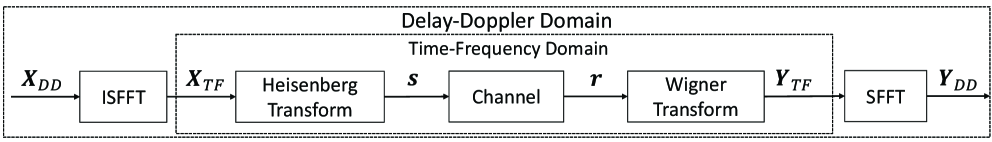
We consider an OTFS system, as illustrated in Fig. 1. In the following, we explain the details of the OTFS transmitter, channel and receiver.
II-A OTFS Transmitter
In the transmitter side, information symbols from a modulation alphabet of size are allocated to an grids in the delay-Doppler (DD) domain, where and represent the number of subcarriers and time slots used, respectively. As illustrated in Fig. 1, the DD domain symbols are transformed into the time-frequency (TF) domain by using the inverse symplectic finite Fourier transform (ISFFT)[1]. Here, the TF domain is discretized to by grids with uniform intervals (Hz) and (seconds), respectively. Therefore, the sampling time is . The TF domain sample is an OTFS frame, which occupies the bandwidth of and the duration of , is given as
| (1) |
where and are -points DFT and -points IDFT matrices, and the -th entries of them are and , respectively. The -th entries of is written as
| (2) |
where represents the -th entries of for . The (discrete) Heisenberg transform[1] is then applied to generate the time domain transmitted signal by using (1) and Kronecker product rule111A matrix multiplication is often expressed by using vectorization with the Kronecker product. That is, , the vector form of the transmitted signal can be written as
| (3) |
where is the pulse-shaping waveform, and we consider the rectangular waveform with a duration of that leads to [16], , and . is the vector form of the transmitted signal, , , and can be written as
| (4) |
We insert the cyclic prefix (CP) at the beginning of each OTFS frame, the length of CP is the same as the index of maximum delay . Thus, the time duration after adding CP is , where . After adding CP, , and is transmitted through a time-varying channel.
II-B OTFS Wireless Channel
The OTFS wireless channel is a time-varying multipath channel, represented by the impulse responses in the DD domain,
| (5) |
where is the Dirac delta function, denotes the -th path gain, and is the total number of paths. Each of the paths represents a channel between a moving reflector/transmitter and a receiver with a different delay and/or Doppler characteristics. The delay and Doppler shifts are given as and, respectively. The ICI depends on the delay and Doppler of the channel as illustrated in [16]. Here, for every path, the randomly selected integers and denote the indices of the delay and Doppler shifts, where and are the indices of the maximum delay and maximum Doppler shifts among all channel paths. Note for every path, the combination of the and are different. For our wireless channel, we assume and , implying maximum channel delay and Doppler shifts of less than seconds and Hz, respectively.
II-C OTFS Receiver
At the receiver side, the time domain received signal is shown as [1]
| (6) |
where is the time-domain received signal , while is the DD domain channel shown in (5). The received signal is then sampled at , where . After discarding CP, the discrete received signal is obtained from (5) and (6), written as
| (7) |
We then write (7) in the vector form as
| (8) |
where is the complex independent and identically distributed (i.i.d.) white Gaussian noise that follows , is the variance of the noise. , denotes a matrix obtained by circularly left shifting the columns of the identity matrix by . is the Doppler shift diagonal matrix, , and denotes a diagonalization operation on a vector. Note that the matrices and model the delay and Doppler shifts in (5), respectively. As shown in Fig. 1, the TF domain received signal is obtained by applying the Wigner transform [16], shown as,
| (9) |
where , is the rectangular waveform with a duration in the receiver, and . Then the DD domain received signal is obtained by using the symplectic finite Fourier transform (SFFT), which is
| (10) |
By following the vectorization with Kronecker product rule, we can rewrite (10) as
| (11) |
By substituting (3) into (8) and (11) we obtain
| (12) |
where and denote the effective channel and noise in the DD domain, respectively. Here, is an i.i.d. Gaussian noise, since is a unitary orthogonal matrix [1, 16]. For convenience, we transform complex-valued model in (12) into real-valued model. Accordingly, , , , , and are the real and imaginary parts, respectively. Thus, the variance of is and are vectors of size and is a matrix of size . Then, we can rewrite (12) as
| (13) |
We assume is known at the detector side. For notation simplicity, we omit the subscript of in (13) and just write it as in all subsequent sections. The signal-to-noise ratio (SNR) of the system is defined as .
III MMSE-BPIC Detector
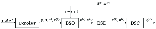
In this section, we briefly describe the BPIC detector that employs MMSE denoiser, recently proposed in [15]. The structure of the BPIC detector is shown in Fig. 2. It consists of four modules: Denoiser, Bayesian symbol observation (BSO), Bayesian symbol estimation (BSE), and decision statistics combining (DSC).
In the Denoiser module, the MMSE scheme is used to obtain the initial symbol estimates in the first BPIC iteration [15] as shown in Fig. 2. The MMSE denoiser can be expressed as
| (14) |
In the BSO module, the matched filter based PIC scheme is used to detect the transmitted symbols, shown as
| (15) |
where is the soft estimate of -th symbol in iteration , is the -th column of matrix . is the vector of the estimated symbol. The variance of the -th symbol estimate is derived in[15] as
| (16) |
where is the -th element in a vector of symbol estimates variance in iteration and , we set because we have no prior knowledge of the variance at the beginning. Then the estimated symbol and variance are forwarded to the BSE module, as shown in Fig. 2
In the BSE module, we compute the Bayesian symbol estimates and the variance of the -th symbol obtained from the BSO module. given as
| (17) |
| (18) |
where is obtained from the BSO module and it is normalized so that . The outputs of the BSE module, and are then sent to the following DSC module.
The DSC module performs a linear combination of the symbol estimates in two consecutive iterations, shown as
| (19) |
| (20) |
The weighting coefficient is determined by maximizing the signal-to-interference-plus-noise-ratio variance, given as
| (21) |
where is defined as the instantaneous square error of the -th symbol estimate, computed by using the MRC filter,
| (22) |
The weighted symbol estimates and their variance are then returned to the BSO module to continue the iteration. After iterations, is taken as a vector of symbol estimates.
IV D-DIP denoiser For symbol estimation
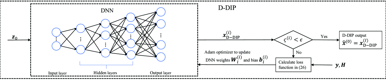
In this section, we propose D-DIP to improve the initial symbol estimates performance of the BPIC detector, and the whole iterative process of D-DIP is shown in Fig. 3.
The DNN used in D-DIP is classified as a fully connected decoder DNN that consists of fully connected layers. Those layers can be broken down into an input layer, an output layer and three hidden layers with p1 = 4, p2 = 8, p3 = 16, p4 = 32, p5 = neurons, respectively. We use a random vector drawn from a normal distribution of size 4x1 as the input of the DNN first layer (i.e., input layer). is fixed during the D-DIP iterative process.
DNN output at iteration is obtained by passing through 5 layers, shown as
| (23) |
where is a constant used to control the output range of the DNN and is the output of layer at iteration ,
| (24) |
where , represents the weight matrix between layer and at iteration . is the bias vector in layer at iteration . In the beginning, each entry of and are initialized randomly following a uniform distribution with a range of [17], where represents the number of neurons in layer . is an activation function used after each layer.
After that, we use a stopping scheme in [18] to control the iterative process of D-DIP to avoid the overfitting problem due to the parameterization feature in the DIP. The stopping scheme is based on calculating the variance of the DNN output, given as
| (25) |
where is the variance value at iteration . When , the variance calculation is inactive. is a constant determined based on the experiments and should be smaller than the iterations needed for D-DIP to converge. As shown in Fig. 3, we compare with a threshold . If the iterative process of D-DIP will stop, and the output of D-DIP is then forwarded to BPIC as initial symbol estimates, i.e., , where is the number of the last D-DIP iteration. Otherwise use mean square error (MSE) to calculate the loss shown as
| (26) |
The DNN parameters that consist of weights and biases are then optimized by using Adam optimizer [19] and the calculated loss in (26). The process is then repeated as shown in Fig. 3.
V Complexity Analysis
In this section, we analyze the computational complexity of the proposed D-DIP-BPIC detector. As for the complexity of D-DIP, the computational complexity of fully-connected layers is matrix vector multiplications with a cost of , where denotes the number of iterations needed for D-DIP. The computational complexity for different detection algorithms is shown in Table I, where represents the iterations needed for the BPIC, UAMP, EP and BPICNet detectors. For instance, for , the complexity of D-DIP-BPIC is approximately 1.5 times lower than MMSE-BPIC, UAMP and BPICNet. The complexity of D-DIP-BPIC is approximately 15 times lower than EP. Thus our proposed detector has the lowest complexity compared to above high-performance detectors.
Note that BPICNet has an extra complexity due to training requirements. BPICNet uses a large data set used for the training prior to deployment. For example, is used in [10].
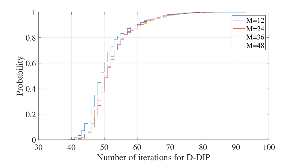
Fig. 4 shows the cumulative distribution function (CDF) of (i.e., the number of D-DIP iterations needed to satisfy the stopping scheme (25)) for . The figure shows that the number of iterations required for D-DIP to converge, , is not sensitive to the OTFS frame size (i.e., and ) which is a significant advantage.
| Detector | Complexity order (Training) | Complexity order (Deployment) |
| MMSE-BPIC[5] | Not required | |
| UAMP[20] | Not required | |
| EP[7] | Not required | |
| BPICNet[10] | ||
| D-DIP-BPIC | Not required |
VI Numerical results
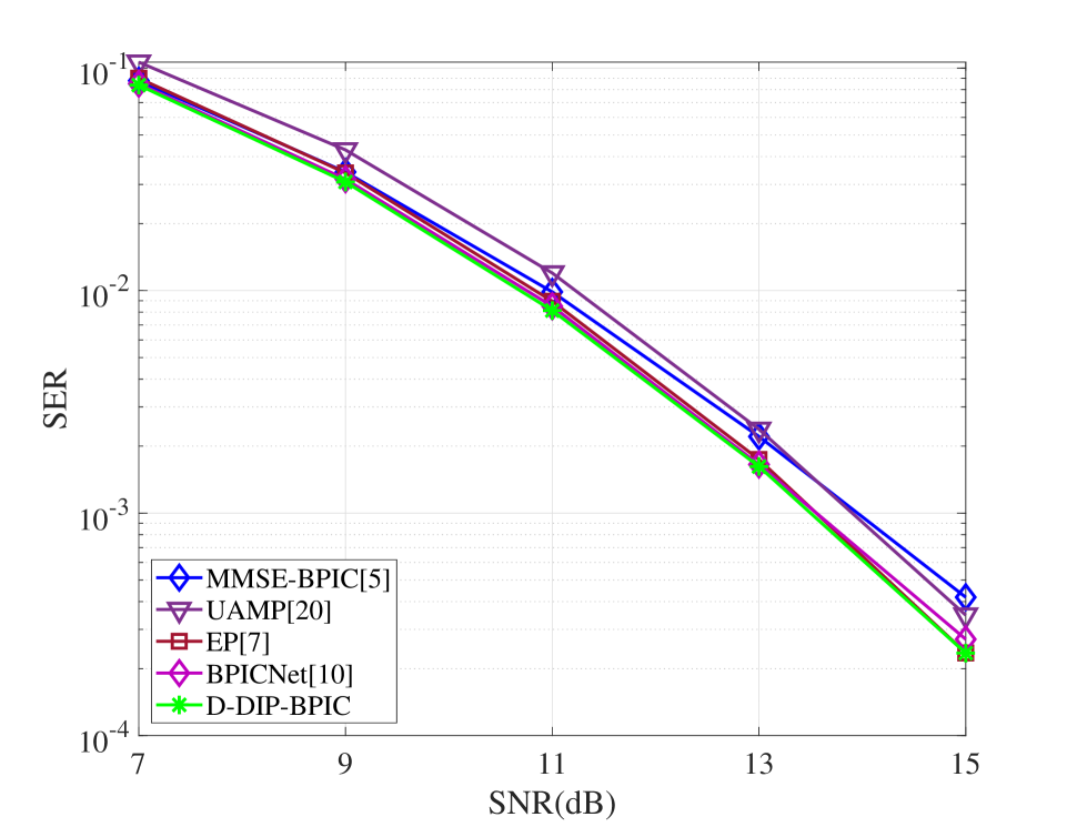
In this section, we evaluate the performance of our proposed detector by comparing its SER performance with those in MMSE-BPIC [5], UAMP [20], EP [7] and BPICNet [10]. Here we use UAMP in [20] instead, because the UAMP proposed in [6] is not suitable for our system model as shown in [5]. For the simulations, we set , kHz. The carrier frequency is set to GHz. The -QAM modulation is employed for the simulations, and we set that is corresponding to the normalized power of constellations to normalize the DNN output. The same DNN parameters described in section IV (e.g., number of layers and number of neurons in each layer) are used in the DNN for all simulations. We use the Adam optimizer with a learning rate of to optimize the DNN parameters. The stopping criteria parameter for (25), is set to 30, and the threshold is set to 0.001. The number of iterations for the BPIC, UAMP, EP and BPICNet is set to to ensure convergence. For the training setting of BPICNet, we use the same setting in [10], where and 500 epochs are used during the training process, in each epoch, 40 batches of 256 samples were generated. is randomly chosen and the values of SNR are uniformly distributed in a certain range, more details are shown in [10].
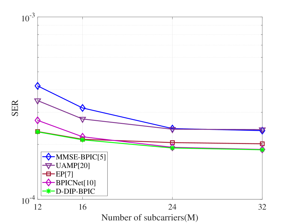
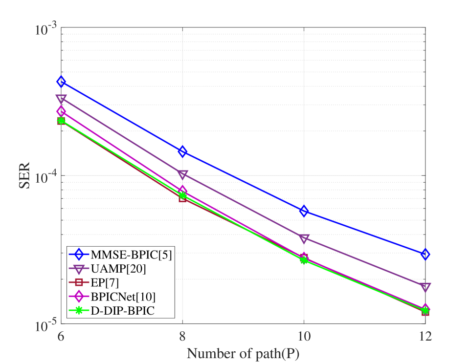
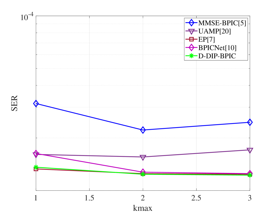
Fig. 5(a) demonstrates that the proposed D-DIP-BPIC detector achieves around 0.5 dB performance gain over MMSE-BPIC and UAMP. In fact, its SER performance is very close to BPICNet and EP. Fig. 5(b) evaluates the scalability of our proposed D-DIP-BPIC detector. As we increase the OTFS frame size (i.e., number of subcarriers), D-DIP-BPIC remains the outperformance over MMSE-BPIC and UAMP and achieves a close to BPICNet and EP performance. Fig. 5(c) shows that when the number of paths (e.g., mobile reflectors) increases, the D-DIP-BPIC detector still can achieve close to BPICNet and EP performance and outperform others. As shown in Fig. 5(d), it is obvious that the performance of the BPICNet detector degrades in the case of as compared to as the fidelity of training data is compromised while our D-DIP-BPIC still retains its benefit.
VII Conclusion
We proposed an untrained neural network based OTFS detector that can achieve excellent performance compared to state-of-the-art OTFS detectors. Our simulation results showed that the proposed D-DIP-BPIC detector achieves a 0.5 dB SER performance improvement over MMSE-BPIC, and achieve a close to EP SER performance with much lower complexity.
References
- [1] R. Hadani, S. Rakib, M. Tsatsanis, A. Monk, A. J. Goldsmith, A. F. Molisch, and R. Calderbank, “Orthogonal time frequency space modulation,” in Proc. IEEE Wireless Commun. and Netw. Conf. (WCNC), USA, Mar. 2017, pp. 1–6.
- [2] T. Jiang, H. H. Chen, H. C. Wu, and Y. Yi, “Channel modeling and inter-carrier interference analysis for V2V communication systems in frequency-dispersive channels,” Mob. Netw. Appl., vol. 15, no. 1, pp. 4–12, May 2010.
- [3] P. Raviteja, K. T. Phan, Y. Hong, and E. Viterbo, “Interference cancellation and iterative detection for orthogonal time frequency space modulation,” IEEE Trans. Wirel. Commun., vol. 17, no. 10, pp. 6501–6515, Aug. 2018.
- [4] M. Khumalo, W. T. Shi, and C. K. Wen, “Fixed-point implementation of approximate message passing (AMP) algorithm in massive MIMO systems,” Digit. Commun. Netw., vol. 2, no. 4, pp. 218–224, Sept. 2016.
- [5] X. Qu, A. Kosasih, W. Hardjawana, V. Onasis, and B. Vucetic, “Bayesian-based symbol detector for orthogonal time frequency space modulation systems,” in Proc. IEEE Int. Symb. Pers. Indoor Mob. Radio Commun. (PIMRC), Finland, Sept. 2021.
- [6] Z. Yuan, F. Liu, W. Yuan, Q. Guo, Z. Wang, and J. Yuan, “Iterative detection for orthogonal time frequency space modulation with unitary approximate message passing,” IEEE Trans. Wireless Commun., vol. 21, no. 2, pp. 714–725, 2022.
- [7] F. Long, K. Niu, and J. Lin, “Low complexity block equalizer for OTFS based on expectation propagation,” IEEE Wireless Commun. Lett., vol. 11, no. 2, pp. 376–380, Feb. 2022.
- [8] P. Singh, A. Gupta, H. B. Mishra, and R. Budhiraja. Low-complexity ZF/MMSE receivers for MIMO-OTFS systems with imperfect CSI. [Online]. Available: https://arxiv.org/abs/2010.04057
- [9] Y. K. Enku, B. Bai, F. Wan, C. U. Guyo, I. N. Tiba, C. Zhang, and S. Li, “Two-dimensional convolutional neural network-based signal detection for OTFS systems,” IEEE Wireless Commun. Lett., vol. 10, no. 11, pp. 2514–2518, 2021.
- [10] A. Kosasih, X. Qu, W. Hardjawana, C. Yue, and B. Vucetic, “Bayesian neural network detector for an orthogonal time frequency space modulation,” IEEE Wireless Commun. Lett., vol. 11, no. 12, pp. 2570–2574, 2022.
- [11] E. Strubell, A. Ganesh, and A. McCallum, “Energy and policy considerations for deep learning in NLP,” in Annu. Meet. Assoc. Comput. Linguist. (ACL), Jul. 2019, pp. 3645–3650.
- [12] A. Linden, “Is synthetic data the future of AI?” gartner.com. https://www.gartner.com/en/newsroom/press-releases/2022-06-22-is-synthetic-data-the-future-of-ai (accessed Jan. 8, 2023).
- [13] V. Lempitsky, A. Vedaldi, and D. Ulyanov, “Deep image prior,” in Proc. IEEE/CVF Conf. Comput. Vis. Pattern Recognit., USA, Jun. 2018, pp. 9446–9454.
- [14] M. Z. Darestani and R. Heckel, “Accelerated MRI with un-trained neural networks,” IEEE Trans. Comput. Imag., vol. 7, pp. 724–733, 2021.
- [15] A. Kosasih, V. Miloslavskaya, W. Hardjawana, C. She, C. K. Wen, and B. Vucetic, “A Bayesian receiver with improved complexity-reliability trade-off in massive MIMO systems,” IEEE Trans. Commun., vol. 69, no. 9, pp. 6251–6266, Sept. 2021.
- [16] P. Raviteja, Y. Hong, E. Viterbo, and E. Biglieri, “Practical pulse-shaping waveforms for reduced-cyclic-prefix OTFS,” IEEE Trans. Vehic. Technol., vol. 68, no. 1, pp. 957–961, Jan. 2019.
- [17] K. He, X. Zhang, S. Ren, and J. Sun, “Delving deep into rectifiers: Surpassing human-level performance on imagenet classification,” in Proc. IEEE Int. Conf. Comput. Vis. (ICCV), Chile, Dec. 2015, pp. 1026–1034.
- [18] H. Wang, T. Li, Z. Zhuang, T. Chen, H. Liang, and J. Sun, “Early stopping for deep image prior,” 2021. [Online]. Available: https://arxiv.org/abs/2112.06074
- [19] D. P. Kingma and J. Ba, “Adam: A method for stochastic optimization,” in Proc. Int. Conf. Learn. Represent. (ICLR), USA, 2015, pp. 1–15.
- [20] Z. Yuan, Q. Guo, and M. Luo, “Approximate message passing with unitary transformation for robust bilinear recovery,” IEEE Trans. Signal Process., vol. 69, pp. 617–630, 2021.