Two-Stage Single Image Reflection Removal
with Reflection-Aware Guidance
Abstract
Removing undesired reflection from an image captured through a glass surface is a very challenging problem with many practical application scenarios. For improving reflection removal, cascaded deep models have been usually adopted to estimate the transmission in a progressive manner. However, most existing methods are still limited in exploiting the result in prior stage for guiding transmission estimation. In this paper, we present a novel two-stage network with reflection-aware guidance (RAGNet) for single image reflection removal (SIRR). To be specific, the reflection layer is firstly estimated due to that it generally is much simpler and is relatively easier to estimate. Reflection-aware guidance (RAG) module is then elaborated for better exploiting the estimated reflection in predicting transmission layer. By incorporating feature maps from the estimated reflection and observation, RAG can be used (i) to mitigate the effect of reflection from the observation, and (ii) to generate mask in partial convolution for mitigating the effect of deviating from linear combination hypothesis. A dedicated mask loss is further presented for reconciling the contributions of encoder and decoder features. Experiments on five commonly used datasets demonstrate the quantitative and qualitative superiority of our RAGNet in comparison to the state-of-the-art SIRR methods. The source code and pre-trained model are available at https://github.com/liyucs/RAGNet.
 |

|

|

|
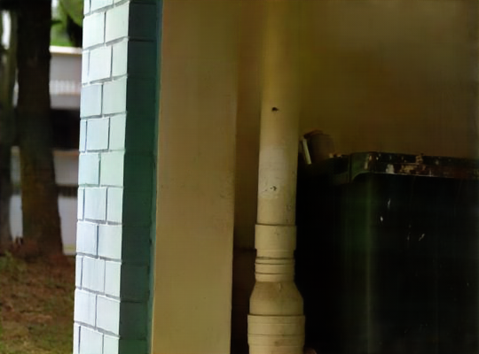
| Observation | Predicted Reflection | Visualization of | Ours |
 |

|

|

|
| CEILNet [4] | BDN [39] | Lei et al. [21] | IBCLN [14] |
1 Introduction
Reflections are commonly observed in images taken through glass, where the light reflected by the glass (\ie, reflection) and that from the objects behind the glass (\ie, transmission) are both captured by the camera. Undesired reflections inevitably degrade image visual quality and hinder many subsequent vision applications such as autonomous driving and entertainment, making reflection removal both very challenging and practically valuable in low level vision [20, 4, 35]. To mitigate the ill-posedness of reflection removal, early studies usually resort to multiple input images captured under different illumination conditions, focal lengths, polarizer angles, and camera viewpoints. On the contrary, single image reflection removal (SIRR) [41, 39, 14] is more common in task setting and practically more significant, and has received considerable interest in the recent few years.
Following the formulation in [35, 41], the input image, \ie, an observation , can be viewed as a linear combination of a transmission layer and a reflection layer , \ie, . The goal of SIRR is to recover the transmission layer for the observation . Unfortunately, the intrinsic ill-posedness of SIRR makes it very challenging to learn a direct mapping from the input image to the transmission . To ease the difficulty of training SIRR, cascaded deep models are usually adopted to mitigate the uncertainty of transmission estimation [4, 39, 14]. For example, [4] first estimates the edge map and then the transmission, while [39] and [14] progressively refine the estimation of reflection and transmission layers. However, there remain several interesting issues to further investigate (i) what should be estimated in the prior stage and (ii) how to exploit the result in prior stage for guiding succeeding transmission estimation, thereby leaving some leeway in improving SIRR.
In this paper, we take a step forward to address the above issues, and present a novel two-stage network with reflection-aware guidance (RAGNet). To be specific, our RAGNet first estimates the reflection layer in the first stage. Then, it takes both the estimated reflection and observation as the input to predict the transmission layer . Fig. 1 shows an example of an input image as well as the estimated reflection by our RAGNet. The reasons to estimate the reflection layer in the first stage can be explained from three aspects. First, the reflection layer generally is much simpler than the transmission layer and is relatively easier to estimate. Second, the estimated reflection is beneficial to transmission estimation. For example, the difference between the observation and estimated reflection, \ie, , can serve as a reasonable initialization of the transmission. Third, the linear combination may not hold true for real-world observations, especially those images with heavy and bright reflection (see Fig. 1). Also, the illumination of estimated reflection is helpful in finding the regions violating the linear combination hypothesis.
Furthermore, we elaborate a reflection-aware guidance (RAG) module for better exploiting the estimated reflection in the second stage. As summarized in Table 1, the output of the prior stage is concatenated with the original observation as the input of the subsequent stage in [39, 4]. Li et al. [14] further applied a recurrent layer (\ie, LSTM [10]) to exploit the deep features across stages. In comparison, the second stage of RAGNet includes an encoder for the estimated reflection and an encoder-decoder for the original observation. For each block of the decoder, an RAG module is elaborated for better leveraging the estimated reflection from two aspects. On the one hand, the encoder feature map of the reflection is utilized to suppress that of the observation, and their difference is then concatenated with the decoder feature map of the observation. On the other hand, the encoder feature maps of the reflection and observation are incorporated with the decoder feature map to generate a mask indicating the extent to which the transmission is corrupted by heavy reflection. The mask is then collaborated with partial convolution to mitigate the effect of deviating from linear combination hypothesis. And a dedicated mask loss is further presented for reconciling the contributions of encoder and decoder features.
Extensive experiments are conducted on five commonly used real-world datasets to evaluate our RAGNet. With the RAG module, the estimated reflection is effective in guiding the transmission estimation and alleviating the effect of violating linear combination hypothesis. In comparison with the state-of-the-art models [4, 41, 39, 35, 14], our RAGNet performs favorably in terms of both quantitative metrics and visual quality. In general, the main contribution of this work is summarized as follows:
-
•
A SIRR network RAGNet is presented, which involves two stages, \ie, first estimating reflection and then predicting transmission. Its rationality is also explicated to differentiate from existing cascaded SIRR models.
-
•
For better leveraging the estimated reflection in the second stage, the reflection-aware guidance (RAG) module is further introduced to guide the transmission estimation and alleviate the effect of violating linear combination hypothesis.
-
•
Experiments on five popular datasets show that our RAGNet performs favorably against the state-of-the-art methods quantitatively and qualitatively.
2 Related Work
In this section, we briefly review two categories of relevant methods on reflection removal tasks, \ie, multiple image reflection removal and single image reflection removal.
2.1 Multiple Image Reflection Removal
Due to the ill-posed nature, multiple images have been exploited to solve the reflection removal problem by providing extra information. Agrawal et al. [1] used two separate images as input, which are captured with and without flash light, respectively, and Fu et al. [5] further took into consideration the high frequency illumination. Schechner et al. [25] treated the input image as a superimposition of two layers, and novel blur kernels were proposed to eliminate mutual penetration of the separated layers, using images taken with different focal lengths as a clue. Polarization camera is also used to take advantage of the polarization properties of light [24, 36, 21]. In particular, based on the linear hypothesis in raw RGB space, Lei et al. [21] adopted a simple two-stage model but took multiple polarized images as input. In these methods, the behavioral difference between the reflection layer and the transmission layer under different settings serves as an effective clue for reflection removal.
Unlike the aforementioned methods, whose input images are captured in a fixed position, taking images from different viewpoints is another popular way to exploit multiple image information in reflection removal tasks [38, 31, 15, 8, 24, 6, 29, 40, 30, 9, 27]. In particular, Punnappurath et al. [20] leveraged the newly developed dual pixel (DP) cameras, and images captured from two sub-aperture views are readily accessible. Although approaches in the multi-input paradigm can obtain impressive results, the necessity to prepare qualified input images with specially designed hardware or extra human efforts makes them inconvenient, and the prerequisites are unable to be satisfied in many practical scenarios, which boosts the recent prevalence of single image reflection removal.
2.2 Single Image Reflection Removal
As the name implies, SIRR methods merely require a single image as input. Traditional methods employ various priors observed in real-world images to reduce the ill-posedness, such as gradient sparsity prior [13, 32, 2, 23], smoothness prior [16, 34] and ghosting cues [26]. Unfortunately, the representation and generalization ability of such methods is limited, and they are prone to produce poor results in the absence of discriminative hints, which is often the case when using handcrafted priors.
As a remedy, learning based methods have been proposed to solve the SIRR problem by leveraging the capacity of deep convolutional neural networks (CNNs), which mainly focus on data synthesis, loss function and network design. Due to the tremendous effort required to collect sufficient well-aligned real image pairs for model training, Fan et al. [4] generated reflection layers via smoothing and illumination intensity decay, which were then used to synthesize the observation by linear combination. Zhang et al. [41] further adapted the intensity decay to suit reflections with higher illuminance level, and applied random vignette to simulate different camera views. Besides, several loss functions have been particularly designed to leverage the characteristic of reflections. CEILNet [4] constrains the gradient maps of the predicted transmission layer to avoid blurry output. Zhang et al. [41] proposed an exclusion loss by minimizing the correlation between the gradient maps of estimated transmission and reflection layers, based on the observation that the edges in these two layers are unlikely to overlap. Li et al. [14] took advantage of the synthesis model to reconstruct the observation, which is constrained to approximate the input. As to network structure, most recent works follow two main schemes. On the one hand, [41] and [35] extracted input features via a pre-trained VGG-19 [28] model and stack them together for subsequent usage, which exploits multi-scale features and is tolerant of mild misalignment between real-world training pairs. On the other hand, the encoder-decoder framework is exploited in [4, 35, 39, 14], where skip connections are usually integrated for better feature utilization.
Considering the difficulty of directly estimating the transmission layer, cascaded models have been widely adopted in the hope of finding a better reflection removal pathway. Fan et al. [4] first predicted potential edge maps, and then the transmission layer is generated given the edge maps. Yang et al. [39] alternated between reflection and transmission estimation, while Li et al. [14] further incorporated a long short-term memory (LSTM) module [10] to generate the reflection and the transmission layer in a progressive manner. Such multi-stage methods are closely related to our proposed method, however, as further discussed in Sec. 3.1, they are still limited in exploiting the result from prior stage.
We note that the MIRR method [21] also uses a two-stage network but takes raw polarized images with different polarization angles as input. Moreover, it adopts the linear hypothesis and its concatenation-based fusion is limited in exploiting the estimated reflection for the subsequent stage. Empirically, the retraining of adjusted MIRR by feeding a single unpolarized image is still limited in removing heavy and bright reflections (See Fig. 1).
3 Proposed Method
In this section, we first revisit the limitations of existing multi-stage SIRR methods. Then, the overall architecture and the design to exploit reflection-aware guidance are illustrated in detail. Finally, the dedicated mask loss and the learning objective are presented.
3.1 Limitations of existing multi-stage methods
Given an observation , CEILNet [4] predicts a potential edge map for the transmission layer, where a reflection smoothness prior is assumed to distinguish whether the image gradients belong to the transmission layer or the reflection layer. Unfortunately, such smoothness prior is often violated in real scenarios, and the resulting inaccurate edge maps will lead to a degraded performance by providing wrong information to the second stage.
BDN [39] and IBCLN [14] resort to predicting reflection layer in the prior stage. However, a simple concatenation is insufficient to make full use of the predicted reflection layer and is limited in suppressing the heavy and bright reflections, thus BDN [39] often fails to process the reflections in difficult regions (see Fig. 1). IBCLN [14] takes the input image and black image as initial estimation of transmission and reflection, and iteratively refines them with a LSTM [10] module to exploit cross-stage information, which significantly promotes the SIRR performance. Nevertheless, such principle makes the method less efficient and greatly relies on the generation quality in the prior stages, and the errors will also be accumulated across stages, leading to undesired artifacts in some scenarios (\eg, zooming in Fig. 1 for clear observation).
3.2 Overall Architecture Design
Considering the aforementioned limitations, we build a two-stage model, where a reflection-aware guidance (RAG) module is introduced in the second stage to better exploit the reflection layer predicted in the first stage. Specifically, we use a plain U-Net [22] model as the first stage subnetwork, namely , which takes the observation as input and predicts the reflection layer, \ie, . The structure of the second stage subnetwork is shown in Fig. 2, is fed into together with the observation to generate the transmission layer, \ie, . In particular, is composed of two encoders ( and ) and one decoder (), and an RAG module is elaborated in each block of . Kindly refer to the supplementary material for detailed structure configurations.
 |

|
| Input | Predicted |
 |

|


3.3 Reflection-Aware Guidance
As shown in Fig. 1, reflections are spatially nonuniform, whose location and intensity can be roughly predicted in the first stage. The estimated reflection can then be incorporated with the observation for succeeding transmission estimation. However, the estimated reflection may be inaccurate. Furthermore, the linear combination hypothesis may not hold true in regions with high reflection intensities, where few informative features of the transmission are retained in (see Fig. 1). Therefore, estimating the transmission in such regions is more challenging, and is more likely to be an inpainting task. Taking these factors into account, we elaborate an RAG module in each decoder block for (i) generating feature complementary to the decoder and (ii) predicting a mask to indicate the heavy reflection regions for guiding image inpainting.
Given the observation feature , the reflection feature and the decoder feature , the RAG module is designed as shown in Fig. 2. Using and , the difference feature is generated via a subtraction operation to better suppress the reflections, \ie, , which serves as a complement and enhancement to the decoder feature . Furthermore, taking , and as input, the RAG module generates a mask via two convolution layers followed by a sigmoid operation. Note that , where denotes the concatenation operation, and and are masks regarding to and , respectively. With such mask, the model is aware of the regions deviating from the linear combination hypothesis, and recovers the transmission layer in such areas mainly relying on the surrounding decoder feature using image inpainting. The mask is visualized in Fig. 3.
Considering the similarity between inpainting and reflection removal in heavy reflection regions, we deploy a partial convolution [18] alongside each RAG module to better exploit the mask, which was first introduced in image inpainting methods [17, 37]. The mask generated by RAG module ranges from 0 to 1, thus the partial convolution in this paper can be formulated as,
|
, |
(1) |
where and represent the weight and bias of the partial convolution, , and are convolution and entry-wise product respectively. contains the average values of in neighborhood regions, which can be efficiently calculated by a average pooling operation.


| Datasets | CEILNet [4] | Zhang et al. [41] | BDN [39] | ERRNet [35] | Lei et al. [21] | IBCLN [14] | Ours |
| PSNR / SSIM | PSNR / SSIM | PSNR / SSIM | PSNR / SSIM | PSNR / SSIM | PSNR / SSIM | PSNR / SSIM | |
| SIR2 Solid (200) | 23.37 / 0.875 | 22.68 / 0.879 | 22.73 / 0.853 | 24.85 / 0.894 | 23.81 / 0.882 | 24.88 / 0.893 | 26.15 / 0.903 |
| SIR2 Postcard (199) | 20.09 / 0.786 | 16.81 / 0.797 | 20.71 / 0.857 | 21.99 / 0.874 | 21.48 / 0.873 | 23.39 / 0.875 | 23.67 / 0.879 |
| SIR2 Wild (55) | 21.07 / 0.805 | 21.52 / 0.832 | 22.34 / 0.821 | 24.16 / 0.847 | 23.84 / 0.866 | 24.71 / 0.886 | 25.52 / 0.880 |
| Real 20 (20) | 18.87 / 0.692 | 22.55 / 0.788 | 18.81 / 0.737 | 23.19 / 0.817 | 22.35 / 0.793 | 22.04 / 0.772 | 22.95 / 0.793 |
| Average (474) | 21.54 / 0.822 | 20.08 / 0.835 | 21.67 / 0.846 | 23.50 / 0.877 | 22.77 / 0.873 | 24.11 / 0.880 | 24.90 / 0.886 |
3.4 Mask Loss
Furthermore, we design a novel mask loss to better exploit the mask during training RAGNet. As shown in Fig. 1, for areas with heavy reflections, can hardly provide informative features. Therefore, we dispose the values of to approximate in such areas, \ie,
| (2) |
where means the -th layer, denotes the norm, represents the part of that meets the in the square brackets, is the threshold that delimits heavy reflection areas.
However, with only, may be optimized towards a trivial solution , which diminishes the effect of . Therefore, is supposed to be for areas with few reflections, to avoid the trivial solution as a regularization term and force the partial convolution to exploit both and , since both of them are reliable in such areas, \ie,
| (3) |
where means threshold for regions with few reflections.
Note that we do not constrain the mask values in remaining regions, which will be automatically optimized for better transmission estimation. Therefore, the mask loss is formulated as,
| (4) |
and we empirically set and . The effectiveness of mask loss will be further corroborated in ablation studies.
3.5 Learning Objective
 |

|

|

|

|

|

|
 |

|

|

|

|

|

|
| Input | RAGNetI→T | w/o | w/o | w/o | w/o | RAGNet |
To train our RAGNet, several commonly used loss functions are collaborated, including reconstruction loss, perceptual loss [11], exclusion loss [41] and adversarial loss [7].
Reconstruction loss. With synthetic image pairs, we are able to minimize the pixel-wise difference between network outputs , and the corresponding ground-truths , ,
| (5) |
Perceptual loss. Given a pre-trained VGG-19 [28] model , we minimize the difference between , and , in the selected feature layers,
| (6) |
where indicates the index of , , , and layers. The weights are used to balance different layers.
Exclusion loss. Following [41], the exclusion loss is formulated as,
| (7) |
where , and and denote normalization factors. and are gradients of and . is the Frobenius norm. and represent the down-sampling versions of and , where and are the original inputs. In practice, we set = 2, , and .
Adversarial Loss. Adversarial loss is adopted to further enhance the visual quality of the output images. We treat the whole RAGNet as the generator and additionally build a -layer discriminator , whose parameters are updated via,
| (8) |
while the parameters of are optimized by,
| (9) |
Taking the above loss functions into account, the learning objective to train our RAGNet can be formulated as,
| (10) |
where and .
4 Experiments
4.1 Implementation Details
Training Data. Following previous works, the proposed RAGNet is trained with both synthetic and real-world images, and we use the same data synthesis protocol as ERRNet [35]. Specifically, image pairs are chosen from the PASCAL VOC dataset [3], and each pair is used to generate the transmission and the reflection , respectively. In each iteration, we select a pair of two images, whose shorter sides are randomly scaled into , and two patches are then cropped to synthesize the input . For real-world data, Zhang et al. [41] collected 110 input-transmission pairs, and we follow the official split where 90 image pairs are used for training. Since the ground-truth reflection is unavailable, the corresponding reconstruction and and perceptual losses on are omitted when training with real-world images.
Evaluation Datasets. Five commonly used real-world datasets are exploited for evaluation, including 20 image pairs (Real 20) from [41], 45 images (Real 45) from [4] and three subsets from SIR2 [33], including i) SIR2 Wild with 55 wild scene images, ii) SIR2 Solid with 200 controlled scene images of a set of daily-life objects, and iii) SIR2 Postcard with 199 controlled scene images on postcards, which are obtained by using one postcard as transmission and another as reflection. Note that we only give the quantitative results of Real 20 and three SIR2 subsets, since the ground-truth transmission of Real 45 is unavailable.
Implementation Details. The model is optimized by the Adam [12] optimizer with , and a fixed learning rate of . For stable training, we first train for 50 epochs, and then the whole model is jointly trained for another 100 epochs. All the experiments are conducted in the PyTorch [19] environment running on a PC with an Nvidia RTX 2080Ti GPU. The source code and pre-trained model are available at https://github.com/liyucs/RAGNet.
 |

|

|

|

|
 |

|

|

|

|
| Input | RAGNetF | RAGNetF∘M | RAGNet | RAGNet |
| Model | Real 20 | SIR2 Wild |
| PSNR / SSIM | PSNR / SSIM | |
| RAGNetI→T | 20.73 / 0.753 | 24.37 / 0.871 |
| w/o | 20.99 / 0.758 | 24.57 / 0.865 |
| w/o | 21.32 / 0.764 | 25.09 / 0.878 |
| w/o | 22.08 / 0.769 | 25.09 / 0.877 |
| w/o | 22.11 / 0.773 | 25.12 / 0.876 |
| RAGNet | 22.95 / 0.793 | 25.52 / 0.880 |
4.2 Comparison with State-of-the-arts
We compare the proposed RAGNet with five state-of-the-art SIRR methods, \ie, CEILNet [4], Zhang et al. [41], BDN [39], ERRNet [35] , IBCLN [14], as well as the adjusted MIRR method by only taking the observation as the network input, \ie, Lei et al. [21]. We finetune these models on our training dataset and report the better result between the finetuned version and the released one. For Lei et al. [21], we adjust the network input and retrain the model with our training set.
The PSNR and SSIM metrics of all competing methods are reported in Table 2. Note that the results of Real 45 are omitted due to lack of ground-truth. Therefore, a user study is conducted on Real 45 to evaluate the reflection removal quality and the results also show the superiority of our RAGNet. The details are given in the supplementary material. It can be seen that the proposed RAGNet achieves the best performance by PSNR on three of the four datasets, and surpasses all other methods on average quantitative performance by a large margin (0.8dB in PSNR). The quantitative gain against other deep cascaded models [4, 39, 14, 21] also indicates the benefit of appropriate reflection-aware guidance.
Fig. 4 shows the qualitative results and the corresponding ground-truth on three SIR2 subsets and Real 20 dataset, and the results on Real 45 dataset are given in Fig. 5. One can see that CEILNet may fail when the reflections have clear edges, where the smoothness assumption is violated (\eg, the second row of Fig. 4). Zhang et al. [41] is prone to over-processing, which generates dim results with color aberration in most cases, while BDN [39] tends to generate brighter output images than input ones. Moreover, the reflections seem insufficiently removed in the results of ERRNet [35] and IBCLN [14]. In general, our method outperforms the competing methods, and removes the reflection areas more accurately and thoroughly. Please refer to the supplementary material for more qualitative results.
5 Ablation Study
In this section, we perform ablation studies on two outdoor real-world datasets, \ie, Real 20 and SIR2 Wild.
5.1 Two-stage Architecture
Our RAGNet is designed as a two-stage network, which takes reflection as an intermediate result to ease the reflection removal procedure. However, it may be concerned whether a well-designed one-stage network is sufficient for SIRR. To show the necessity and superiority of the two-stage architecture, we additionally design a single-stage variant, namely RAGNetI→T, which directly estimates the transmission layer from the input.
According to Fig. 2, the generation of in RAGNet requires features from two sources, \ie, and . We expect that when reflection is heavy as in Eqn. (2), so that only provides information for recovering heavy reflection areas. When designing RAGNetI→T, we retain the functionality of the skip connection and : one for providing auxiliary information via subtraction operations, the other focuses on gradually recovering . The structure of the one-stage model is provided in the supplementary material. The results in Table 3 and Fig. 6 show that the one-stage variant RAGNetI→T suffers a huge performance degradation, indicating the essentiality of the two-stage architecture for our RAGNet.
| Model | Real 20 | SIR2 Wild |
| PSNR / SSIM | PSNR / SSIM | |
| RAGNetF | 20.93 / 0.750 | 24.47 / 0.875 |
| RAGNetF∘M | 21.60 / 0.772 | 24.86 / 0.875 |
| RAGNet | 21.69 / 0.774 | 24.69 / 0.871 |
| RAGNet | 22.95 / 0.793 | 25.52 / 0.880 |
5.2 RAG Module
Difference Features. To evaluate the effectiveness of difference features, we replace with and keep the other parts of the model unchanged, \ie, the subtraction operation is discarded. As shown in Fig. 6, without , the model performs poorly in suppressing the reflection, leading to an obvious performance drop in Table 3.
Masks. In order to verify the settings about masks, we conduct ablation studies on three variants, (i) RAGNetF: the masks are totally discarded, where the partial convolution is accordingly replaced by vanilla convolution. (ii) RAGNetF∘M: the masks are multiplied with the feature , in other words, the renormalization operation in partial convolutions is removed. (iii) RAGNet: a unified one-channel mask is predicted for and respectively, \ie, and , where .
Table 4 shows the quantitative results of the ablation studies on masks. It can be seen that our RAGNet surpasses its variants RAGNetF and RAGNetF∘M in both PSNR and SSIM, indicating the effectiveness of the deployment of mask and partial convolution. Furthermore, the ablation study on RAGNet shows that predicting a per-channel mask better suits the SIRR task in our framework.
Fig. 7 shows the qualitative results of the ablation studies. It can be seen that, all of RAGNetF, RAGNetF∘M and RAGNet fail to remove the heavy reflections, especially in complex environments (\eg, in the second row of Fig. 7, the light on the ground is very similar to the reflections). RAGNet outperforms the others by recovering the heavy reflection areas with contextual information, making the output image visually pleasant. Moreover, by integrating partial convolution, the reflection removal performance is also enhanced for images with mild reflections.
5.3 Mask Loss
From the aspect of the proposed mask loss, we conduct three experiments, \ie, discarding , and both of them, respectively. Table 3 and Fig. 6 show that with the mask loss, the performance of our RAGNet is improved by a large margin. Furthermore, one can see that both items of the specifically designed mask loss are essential for RAGNet, and greatly boost the quantitative performance and visual quality. The thresholds and in Eqns. (2) and (3) are discussed in the supplementary material.
6 Conclusion
In this paper, we investigated the two-stage framework for the single image reflection removal (SIRR) task, and presented an RAGNet to exploit the reflection-aware guidance via the RAG module. The RAG module suppresses the reflection by using the difference between observation and reflection features, while a mask is generated to indicate the extent to which the transmission is corrupted by heavy reflection and to collaborate with partial convolution for mitigating the effect of deviating from the linear combination hypothesis. A mask loss is accordingly designed for reconciling the contributions of encoder and decoder features. Extensive experiments on five widely used real-world datasets indicate that the proposed RAGNet outperforms the state-of-the-art methods by a large margin.
References
- [1] Amit Agrawal, Ramesh Raskar, Shree K. Nayar, and Yuanzhen Li. Removing photography artifacts using gradient projection and flash-exposure sampling. In ACM SIGGRAPH, pages 828–835, 2005.
- [2] Nikolaos Arvanitopoulos, Radhakrishna Achanta, and Sabine Susstrunk. Single image reflection suppression. In IEEE Conference on Computer Vision and Pattern Recognition, pages 4498–4506, 2017.
- [3] Mark Everingham, Luc Van Gool, Christopher KI Williams, John Winn, and Andrew Zisserman. The pascal visual object classes (voc) challenge. International Journal of Computer Vision, 88(2):303–338, 2010.
- [4] Qingnan Fan, Jiaolong Yang, Gang Hua, Baoquan Chen, and David Wipf. A generic deep architecture for single image reflection removal and image smoothing. In IEEE International Conference on Computer Vision, pages 3238–3247, 2017.
- [5] Ying Fu, Antony Lam, Imari Sato, Takahiro Okabe, and Yoichi Sato. Separating reflective and fluorescent components using high frequency illumination in the spectral domain. In IEEE International Conference on Computer Vision, pages 457–464, 2013.
- [6] Kun Gai, Zhenwei Shi, and Changshui Zhang. Blind separation of superimposed moving images using image statistics. IEEE Transactions on Pattern Analysis and Machine Intelligence, 34(1):19–32, 2012.
- [7] Ian Goodfellow, Jean Pouget-Abadie, Mehdi Mirza, Bing Xu, David Warde-Farley, Sherjil Ozair, Aaron Courville, and Yoshua Bengio. Generative adversarial nets. In Advances in Neural Information Processing Systems, pages 2672–2680, 2014.
- [8] Xiaojie Guo, Xiaochun Cao, and Yi Ma. Robust separation of reflection from multiple images. In IEEE Conference on Computer Vision and Pattern Recognition, pages 2187–2194, 2014.
- [9] Byeong-Ju Han and Jae-Young Sim. Reflection removal using low-rank matrix completion. In IEEE Conference on Computer Vision and Pattern Recognition, pages 5438–5446, 2017.
- [10] Sepp Hochreiter and Jürgen Schmidhuber. Long short-term memory. Neural Computation, 9(8):1735–1780, 1997.
- [11] Justin Johnson, Alexandre Alahi, and Li Fei-Fei. Perceptual losses for real-time style transfer and super-resolution. In European Conference on Computer Vision, pages 694–711, 2016.
- [12] Diederik P Kingma and Jimmy Ba. Adam: A method for stochastic optimization. arXiv preprint arXiv:1412.6980, 2014.
- [13] Anat Levin and Yair Weiss. User assisted separation of reflections from a single image using a sparsity prior. IEEE Transactions on Pattern Analysis and Machine Intelligence, 29(9):1647–1654, 2007.
- [14] Chao Li, Yixiao Yang, Kun He, Stephen Lin, and John E. Hopcroft. Single image reflection removal through cascaded refinement. In IEEE Conference on Computer Vision and Pattern Recognition, pages 3565–3574, 2020.
- [15] Yu Li and Michael S. Brown. Exploiting reflection change for automatic reflection removal. In IEEE International Conference on Computer Vision, pages 2432–2439, 2013.
- [16] Yu Li and Michael S. Brown. Single image layer separation using relative smoothness. In IEEE Conference on Computer Vision and Pattern Recognition, pages 2752–2759, 2014.
- [17] Guilin Liu, Fitsum A. Reda, Kevin J. Shih, Ting-Chun Wang, Andrew Tao, and Bryan Catanzaro. Image inpainting for irregular holes using partial convolutions. In European Conference on Computer Vision, pages 85–100, 2018.
- [18] Guilin Liu, Kevin J Shih, Ting-Chun Wang, Fitsum A Reda, Karan Sapra, Zhiding Yu, Andrew Tao, and Bryan Catanzaro. Partial convolution based padding. arXiv preprint arXiv:1811.11718, 2018.
- [19] Adam Paszke, Sam Gross, Francisco Massa, Adam Lerer, James Bradbury, Gregory Chanan, Trevor Killeen, Zeming Lin, Natalia Gimelshein, Luca Antiga, et al. Pytorch: An imperative style, high-performance deep learning library. In Advances in Neural Information Processing Systems, pages 8026–8037, 2019.
- [20] Abhijith Punnappurath and Michael S. Brown. Reflection removal using a dual-pixel sensor. In IEEE Conference on Computer Vision and Pattern Recognition, pages 1556–1565, 2019.
- [21] Chenyang Lei, Xuhua Huang, Mengdi Zhang, Qiong Yan, Wenxiu Sun, and Qifeng Chen. Polarized reflection removal with perfect alignment in the wild. In IEEE Conference on Computer Vision and Pattern Recognition, pages 1750–1758, 2020.
- [22] Olaf Ronneberger, Philipp Fischer, and Thomas Brox. U-net: Convolutional networks for biomedical image segmentation. In International Conference on Medical Image Computing and Computer-assisted Intervention, pages 234–241, 2015.
- [23] Tushar Sandhan and Jin Young Choi. Anti-glare: Tightly constrained optimization for eyeglass reflection removal. In IEEE Conference on Computer Vision and Pattern Recognition, pages 1241–1250, 2017.
- [24] Bernard Sarel and Michal Irani. Separating transparent layers through layer information exchange. In European Conference on Computer Vision, pages 328–341, 2004.
- [25] Yoav Y. Schechner, Nahum Kiryati, and Ronen Basri. Separation of transparent layers using focus. pages 25–39, 2000.
- [26] YiChang Shih, Dilip Krishnan, Fredo Durand, and William T. Freeman. Reflection removal using ghosting cues. In IEEE Conference on Computer Vision and Pattern Recognition, pages 3193–3201, 2015.
- [27] Christian Simon and In Kyu Park. Reflection removal for in-vehicle black box videos. In IEEE Conference on Computer Vision and Pattern Recognition, pages 4231–4239, 2015.
- [28] Karen Simonyan and Andrew Zisserman. Very deep convolutional networks for large-scale image recognition. arXiv preprint arXiv:1409.1556, 2014.
- [29] Sudipta N Sinha, Johannes Kopf, Michael Goesele, Daniel Scharstein, and Richard Szeliski. Image-based rendering for scenes with reflections. ACM Transactions on Graphics, 31(4):1–10, 2012.
- [30] Chao Sun, Shuaicheng Liu, Taotao Yang, Bing Zeng, Zhengning Wang, and Guanghui Liu. Automatic reflection removal using gradient intensity and motion cues. In ACM International Conference on Multimedia, pages 466–470, 2016.
- [31] Richard Szeliski, Shai Avidan, and Padmanabhan Anandan. Layer extraction from multiple images containing reflections and transparency. In IEEE Conference on Computer Vision and Pattern Recognition, pages 246–253, 2000.
- [32] Renjie Wan, Boxin Shi, Ling-Yu Duan, Ah-Hwee Tan, Wen Gao, and Alex C Kot. Region-aware reflection removal with unified content and gradient priors. IEEE Transactions on Image Processing, 27(6):2927–2941, 2018.
- [33] Renjie Wan, Boxin Shi, Ling-Yu Duan, Ah-Hwee Tan, and Alex C. Kot. Benchmarking single-image reflection removal algorithms. In IEEE International Conference on Computer Vision, pages 3922–3930, 2017.
- [34] Renjie Wan, Boxin Shi, Ah-Hwee Tan, and Alex C. Kot. Depth of field guided reflection removal. In IEEE International Conference on Image Processing, pages 21–25, 2016.
- [35] Kaixuan Wei, Jiaolong Yang, Ying Fu, David Wipf, and Hua Huang. Single image reflection removal exploiting misaligned training data and network enhancements. In IEEE Conference on Computer Vision and Pattern Recognition, pages 8178–8187, 2019.
- [36] Patrick Wieschollek, Orazio Gallo, Jinwei Gu, and Jan Kautz. Separating reflection and transmission images in the wild. In European Conference on Computer Vision, pages 89–104, 2018.
- [37] Chaohao Xie, Shaohui Liu, Chao Li, Ming-Ming Cheng, Wangmeng Zuo, Xiao Liu, Shilei Wen, and Errui Ding. Image inpainting with learnable bidirectional attention maps. In IEEE International Conference on Computer Vision, pages 8858–8867, 2019.
- [38] Tianfan Xue, Michael Rubinstein, Ce Liu, and William T Freeman. A computational approach for obstruction-free photography. ACM Transactions on Graphics, 34(4):1–11, 2015.
- [39] Jie Yang, Dong Gong, Lingqiao Liu, and Qinfeng Shi. Seeing deeply and bidirectionally: A deep learning approach for single image reflection removal. In European Conference on Computer Vision, pages 654–669, 2018.
- [40] Jiaolong Yang, Hongdong Li, Yuchao Dai, and Robby T. Tan. Robust optical flow estimation of double-layer images under transparency or reflection. In IEEE Conference on Computer Vision and Pattern Recognition, pages 1410–1419, 2016.
- [41] Xuaner Zhang, Ren Ng, and Qifeng Chen. Single image reflection separation with perceptual losses. In IEEE Conference on Computer Vision and Pattern Recognition, pages 4786–4794, 2018.
Supplemental Materials
A Network Structure
Our RAGNet is comprised of two components, \ie, a to predict the reflection layer and a to generate the transmission layer on the basis of .
The subnetworks and both follow the structual configuration of U-Net. Especially, all the encoders of and share the same network structure, while the decoders differ slightly in the use of partial convolution. The detailed structures of and are shown in Table A.
| Encoder | Decoder | ||||
| Layer | Output size | Filter | Layer | Output size | Filter |
| Conv, ReLU | Transposed Conv | ||||
| Conv, ReLU | Concat, , ReLU | ||||
| MaxPool | - | [Conv, ReLU] 3 | |||
| Conv, ReLU | |||||
| Conv, ReLU | Transposed Conv | ||||
| Conv, ReLU | Concat, , ReLU | ||||
| MaxPool | - | [Conv, ReLU] 3 | |||
| Conv, ReLU | |||||
| Conv, ReLU | Transposed Conv | ||||
| [Conv, ReLU] 3 | Concat, , ReLU | ||||
| MaxPool | - | Conv, ReLU | |||
| Conv, ReLU | |||||
| Conv, ReLU | Transposed Conv | ||||
| [Conv, ReLU] 3 | Concat, , ReLU | ||||
| MaxPool | - | Conv, ReLU | |||
| [Conv, ReLU] 4 | Conv, ReLU | ||||
| Conv, Sigmoid | |||||
B One-stage Structure
The structure of single-stage network RAGNetI→T used in ablation study is shown in Fig. A. RAGNetI→T predicts transmission layer directly from observation .
C Running Time and Number of Parameters
RAGNetI→T has 63.5M parameters, which is slightly less than Zhang et al.(77.6M) and BDN (75.2M) but achieves comparable performance according to Tables 2 and 3 in the main text. While RAGNet (including and ) has 130.9M parameters. We also note that RAGNet has a running time of 0.15 per image (540400) on an Nvidia RTX 2080Ti GPU, which is comparable to Zhang et al.and is faster than the other competing methods (see Table. D).
D Ablation Study on and
and are thresholds that define the intensity levels of reflection, \ie, areas with reflection intensity higher than are treated as heavy reflection areas, while areas with reflection intensity lower than are treated as weak reflection areas. We conduct an ablation study on and on Real 20 and SIR2 test datasets with two groups of values, \ie, and . Considering the PSNR and SSIM performance exhibited in Fig. B, the final thresholds are set as and .
![[Uncaptioned image]](https://cdn.awesomepapers.org/papers/cb3069a4-b3d5-40b9-aa50-d70d0580f9c0/table.jpg) |
![[Uncaptioned image]](https://cdn.awesomepapers.org/papers/cb3069a4-b3d5-40b9-aa50-d70d0580f9c0/1_input.png)
![[Uncaptioned image]](https://cdn.awesomepapers.org/papers/cb3069a4-b3d5-40b9-aa50-d70d0580f9c0/1_output.png)
![[Uncaptioned image]](https://cdn.awesomepapers.org/papers/cb3069a4-b3d5-40b9-aa50-d70d0580f9c0/2_output.png)
![[Uncaptioned image]](https://cdn.awesomepapers.org/papers/cb3069a4-b3d5-40b9-aa50-d70d0580f9c0/0_output.png)
![[Uncaptioned image]](https://cdn.awesomepapers.org/papers/cb3069a4-b3d5-40b9-aa50-d70d0580f9c0/3_input.png)
![[Uncaptioned image]](https://cdn.awesomepapers.org/papers/cb3069a4-b3d5-40b9-aa50-d70d0580f9c0/3_output.png)
![[Uncaptioned image]](https://cdn.awesomepapers.org/papers/cb3069a4-b3d5-40b9-aa50-d70d0580f9c0/3_ceilnet.jpg)
![[Uncaptioned image]](https://cdn.awesomepapers.org/papers/cb3069a4-b3d5-40b9-aa50-d70d0580f9c0/3_chen.jpg)
![[Uncaptioned image]](https://cdn.awesomepapers.org/papers/cb3069a4-b3d5-40b9-aa50-d70d0580f9c0/3_bdn.jpg)
![[Uncaptioned image]](https://cdn.awesomepapers.org/papers/cb3069a4-b3d5-40b9-aa50-d70d0580f9c0/3_errnet.jpg)
![[Uncaptioned image]](https://cdn.awesomepapers.org/papers/cb3069a4-b3d5-40b9-aa50-d70d0580f9c0/3_ibcln.jpg)
![[Uncaptioned image]](https://cdn.awesomepapers.org/papers/cb3069a4-b3d5-40b9-aa50-d70d0580f9c0/3_ours.jpg)
![[Uncaptioned image]](https://cdn.awesomepapers.org/papers/cb3069a4-b3d5-40b9-aa50-d70d0580f9c0/0_input.jpg)
![[Uncaptioned image]](https://cdn.awesomepapers.org/papers/cb3069a4-b3d5-40b9-aa50-d70d0580f9c0/0_ceilnet.jpg)
![[Uncaptioned image]](https://cdn.awesomepapers.org/papers/cb3069a4-b3d5-40b9-aa50-d70d0580f9c0/0_chen.jpg)
![[Uncaptioned image]](https://cdn.awesomepapers.org/papers/cb3069a4-b3d5-40b9-aa50-d70d0580f9c0/0_bdn.jpg)
![[Uncaptioned image]](https://cdn.awesomepapers.org/papers/cb3069a4-b3d5-40b9-aa50-d70d0580f9c0/0_errnet.jpg)
![[Uncaptioned image]](https://cdn.awesomepapers.org/papers/cb3069a4-b3d5-40b9-aa50-d70d0580f9c0/0_ibcln.jpg)
![[Uncaptioned image]](https://cdn.awesomepapers.org/papers/cb3069a4-b3d5-40b9-aa50-d70d0580f9c0/0_ours.jpg)
![[Uncaptioned image]](https://cdn.awesomepapers.org/papers/cb3069a4-b3d5-40b9-aa50-d70d0580f9c0/1_ceilnet.jpg)
![[Uncaptioned image]](https://cdn.awesomepapers.org/papers/cb3069a4-b3d5-40b9-aa50-d70d0580f9c0/1_chen.jpg)
![[Uncaptioned image]](https://cdn.awesomepapers.org/papers/cb3069a4-b3d5-40b9-aa50-d70d0580f9c0/1_bdn.jpg)
![[Uncaptioned image]](https://cdn.awesomepapers.org/papers/cb3069a4-b3d5-40b9-aa50-d70d0580f9c0/1_errnet.jpg)
![[Uncaptioned image]](https://cdn.awesomepapers.org/papers/cb3069a4-b3d5-40b9-aa50-d70d0580f9c0/1_ibcln.jpg)
![[Uncaptioned image]](https://cdn.awesomepapers.org/papers/cb3069a4-b3d5-40b9-aa50-d70d0580f9c0/1_ours.jpg)
![[Uncaptioned image]](https://cdn.awesomepapers.org/papers/cb3069a4-b3d5-40b9-aa50-d70d0580f9c0/2_input.jpg)
![[Uncaptioned image]](https://cdn.awesomepapers.org/papers/cb3069a4-b3d5-40b9-aa50-d70d0580f9c0/2_ceilnet.jpg)
![[Uncaptioned image]](https://cdn.awesomepapers.org/papers/cb3069a4-b3d5-40b9-aa50-d70d0580f9c0/2_chen.jpg)
![[Uncaptioned image]](https://cdn.awesomepapers.org/papers/cb3069a4-b3d5-40b9-aa50-d70d0580f9c0/2_bdn.jpg)
![[Uncaptioned image]](https://cdn.awesomepapers.org/papers/cb3069a4-b3d5-40b9-aa50-d70d0580f9c0/2_errnet.jpg)
![[Uncaptioned image]](https://cdn.awesomepapers.org/papers/cb3069a4-b3d5-40b9-aa50-d70d0580f9c0/2_ibcln.jpg)
![[Uncaptioned image]](https://cdn.awesomepapers.org/papers/cb3069a4-b3d5-40b9-aa50-d70d0580f9c0/2_ours.jpg)
![[Uncaptioned image]](https://cdn.awesomepapers.org/papers/cb3069a4-b3d5-40b9-aa50-d70d0580f9c0/4_input.png)
![[Uncaptioned image]](https://cdn.awesomepapers.org/papers/cb3069a4-b3d5-40b9-aa50-d70d0580f9c0/4_ceilnet.jpg)
![[Uncaptioned image]](https://cdn.awesomepapers.org/papers/cb3069a4-b3d5-40b9-aa50-d70d0580f9c0/4_chen.png)
![[Uncaptioned image]](https://cdn.awesomepapers.org/papers/cb3069a4-b3d5-40b9-aa50-d70d0580f9c0/4_bdn.png)
![[Uncaptioned image]](https://cdn.awesomepapers.org/papers/cb3069a4-b3d5-40b9-aa50-d70d0580f9c0/4_errnet.png)
![[Uncaptioned image]](https://cdn.awesomepapers.org/papers/cb3069a4-b3d5-40b9-aa50-d70d0580f9c0/4_ibcln.png)
![[Uncaptioned image]](https://cdn.awesomepapers.org/papers/cb3069a4-b3d5-40b9-aa50-d70d0580f9c0/4_ours.png)
![[Uncaptioned image]](https://cdn.awesomepapers.org/papers/cb3069a4-b3d5-40b9-aa50-d70d0580f9c0/5_input.jpg)
![[Uncaptioned image]](https://cdn.awesomepapers.org/papers/cb3069a4-b3d5-40b9-aa50-d70d0580f9c0/5_ceilnet.jpg)
![[Uncaptioned image]](https://cdn.awesomepapers.org/papers/cb3069a4-b3d5-40b9-aa50-d70d0580f9c0/5_chen.jpg)
![[Uncaptioned image]](https://cdn.awesomepapers.org/papers/cb3069a4-b3d5-40b9-aa50-d70d0580f9c0/5_bdn.jpg)
![[Uncaptioned image]](https://cdn.awesomepapers.org/papers/cb3069a4-b3d5-40b9-aa50-d70d0580f9c0/5_errnet.jpg)
![[Uncaptioned image]](https://cdn.awesomepapers.org/papers/cb3069a4-b3d5-40b9-aa50-d70d0580f9c0/5_ibcln.jpg)
![[Uncaptioned image]](https://cdn.awesomepapers.org/papers/cb3069a4-b3d5-40b9-aa50-d70d0580f9c0/5_ours.jpg)
| Method | CEILNet [4] | Zhang [41] | BDN [39] | ERRNet [35] | IBCLN [14] | RAGNetI→T | RAGNet |
| Time () | 0.26 | 0.16 | 0.22 | 0.27 | 0.22 | 0.08 | 0.15 |
| Parameter (M) | 2.2 | 77.6 | 75.2 | 86.7 | 21.2 | 63.5 | 130.9 |
| Datasets | SIR2 Solid (200) | SIR2 Postcard (199) | SIR2 Wild (55) | Real 20 (20) | Nature (20) | Average (494) |
| PSNR / SSIM | PSNR / SSIM | PSNR / SSIM | PSNR / SSIM | PSNR / SSIM | PSNR / SSIM | |
| RAGNet | 26.16 / 0.907 | 24.42 / 0.883 | 25.99 / 0.890 | 22.48 / 0.786 | 22.95 / 0.792 | 25.16 / 0.886 |
| Reflection Intensity | CEILNet [4] | Zhang [41] | BDN [39] | ERRNet [35] | IBCLN [14] | Ours |
| Weak | 21.51 | 19.38 | 21.86 | 23.79 | 24.28 | 25.18 |
| Strong | 21.01 | 20.29 | 21.14 | 21.32 | 21.43 | 23.40 |
![[Uncaptioned image]](https://cdn.awesomepapers.org/papers/cb3069a4-b3d5-40b9-aa50-d70d0580f9c0/16_input.jpg)
![[Uncaptioned image]](https://cdn.awesomepapers.org/papers/cb3069a4-b3d5-40b9-aa50-d70d0580f9c0/16_ceilnet.jpg)
![[Uncaptioned image]](https://cdn.awesomepapers.org/papers/cb3069a4-b3d5-40b9-aa50-d70d0580f9c0/16_chen.jpg)
![[Uncaptioned image]](https://cdn.awesomepapers.org/papers/cb3069a4-b3d5-40b9-aa50-d70d0580f9c0/16_bdn.jpg)
![[Uncaptioned image]](https://cdn.awesomepapers.org/papers/cb3069a4-b3d5-40b9-aa50-d70d0580f9c0/16_errnet.jpg)
![[Uncaptioned image]](https://cdn.awesomepapers.org/papers/cb3069a4-b3d5-40b9-aa50-d70d0580f9c0/16_ibcln.jpg)
![[Uncaptioned image]](https://cdn.awesomepapers.org/papers/cb3069a4-b3d5-40b9-aa50-d70d0580f9c0/16_ours.jpg)
![[Uncaptioned image]](https://cdn.awesomepapers.org/papers/cb3069a4-b3d5-40b9-aa50-d70d0580f9c0/16_gt.jpg)
![[Uncaptioned image]](https://cdn.awesomepapers.org/papers/cb3069a4-b3d5-40b9-aa50-d70d0580f9c0/17_input.jpg)
![[Uncaptioned image]](https://cdn.awesomepapers.org/papers/cb3069a4-b3d5-40b9-aa50-d70d0580f9c0/17_ceilnet.jpg)
![[Uncaptioned image]](https://cdn.awesomepapers.org/papers/cb3069a4-b3d5-40b9-aa50-d70d0580f9c0/17_chen.jpg)
![[Uncaptioned image]](https://cdn.awesomepapers.org/papers/cb3069a4-b3d5-40b9-aa50-d70d0580f9c0/17_bdn.jpg)
![[Uncaptioned image]](https://cdn.awesomepapers.org/papers/cb3069a4-b3d5-40b9-aa50-d70d0580f9c0/17_errnet.jpg)
![[Uncaptioned image]](https://cdn.awesomepapers.org/papers/cb3069a4-b3d5-40b9-aa50-d70d0580f9c0/17_ibcln.jpg)
![[Uncaptioned image]](https://cdn.awesomepapers.org/papers/cb3069a4-b3d5-40b9-aa50-d70d0580f9c0/17_ours.jpg)
![[Uncaptioned image]](https://cdn.awesomepapers.org/papers/cb3069a4-b3d5-40b9-aa50-d70d0580f9c0/17_gt.jpg)
![[Uncaptioned image]](https://cdn.awesomepapers.org/papers/cb3069a4-b3d5-40b9-aa50-d70d0580f9c0/18_input.jpg)
![[Uncaptioned image]](https://cdn.awesomepapers.org/papers/cb3069a4-b3d5-40b9-aa50-d70d0580f9c0/18_chen.jpg)
![[Uncaptioned image]](https://cdn.awesomepapers.org/papers/cb3069a4-b3d5-40b9-aa50-d70d0580f9c0/18_bdn.jpg)
![[Uncaptioned image]](https://cdn.awesomepapers.org/papers/cb3069a4-b3d5-40b9-aa50-d70d0580f9c0/18_errnet.jpg)
![[Uncaptioned image]](https://cdn.awesomepapers.org/papers/cb3069a4-b3d5-40b9-aa50-d70d0580f9c0/18_ibcln.jpg)
![[Uncaptioned image]](https://cdn.awesomepapers.org/papers/cb3069a4-b3d5-40b9-aa50-d70d0580f9c0/18_ours.jpg)
![[Uncaptioned image]](https://cdn.awesomepapers.org/papers/cb3069a4-b3d5-40b9-aa50-d70d0580f9c0/18_gt.jpg)
![[Uncaptioned image]](https://cdn.awesomepapers.org/papers/cb3069a4-b3d5-40b9-aa50-d70d0580f9c0/8_input.png)
![[Uncaptioned image]](https://cdn.awesomepapers.org/papers/cb3069a4-b3d5-40b9-aa50-d70d0580f9c0/8_ceilnet.jpg)
![[Uncaptioned image]](https://cdn.awesomepapers.org/papers/cb3069a4-b3d5-40b9-aa50-d70d0580f9c0/8_chen.png)
![[Uncaptioned image]](https://cdn.awesomepapers.org/papers/cb3069a4-b3d5-40b9-aa50-d70d0580f9c0/8_bdn.png)
![[Uncaptioned image]](https://cdn.awesomepapers.org/papers/cb3069a4-b3d5-40b9-aa50-d70d0580f9c0/8_errnet.png)
![[Uncaptioned image]](https://cdn.awesomepapers.org/papers/cb3069a4-b3d5-40b9-aa50-d70d0580f9c0/8_ibcln.png)
![[Uncaptioned image]](https://cdn.awesomepapers.org/papers/cb3069a4-b3d5-40b9-aa50-d70d0580f9c0/8_ours.png)
![[Uncaptioned image]](https://cdn.awesomepapers.org/papers/cb3069a4-b3d5-40b9-aa50-d70d0580f9c0/8_gt.png)
![[Uncaptioned image]](https://cdn.awesomepapers.org/papers/cb3069a4-b3d5-40b9-aa50-d70d0580f9c0/13_input.jpg)
![[Uncaptioned image]](https://cdn.awesomepapers.org/papers/cb3069a4-b3d5-40b9-aa50-d70d0580f9c0/13_ceilnet.jpg)
![[Uncaptioned image]](https://cdn.awesomepapers.org/papers/cb3069a4-b3d5-40b9-aa50-d70d0580f9c0/13_chen.jpg)
![[Uncaptioned image]](https://cdn.awesomepapers.org/papers/cb3069a4-b3d5-40b9-aa50-d70d0580f9c0/13_bdn.jpg)
![[Uncaptioned image]](https://cdn.awesomepapers.org/papers/cb3069a4-b3d5-40b9-aa50-d70d0580f9c0/13_errnet.jpg)
![[Uncaptioned image]](https://cdn.awesomepapers.org/papers/cb3069a4-b3d5-40b9-aa50-d70d0580f9c0/13_ibcln.jpg)
![[Uncaptioned image]](https://cdn.awesomepapers.org/papers/cb3069a4-b3d5-40b9-aa50-d70d0580f9c0/13_ours.jpg)
![[Uncaptioned image]](https://cdn.awesomepapers.org/papers/cb3069a4-b3d5-40b9-aa50-d70d0580f9c0/13_gt.jpg)
![[Uncaptioned image]](https://cdn.awesomepapers.org/papers/cb3069a4-b3d5-40b9-aa50-d70d0580f9c0/15_input.jpg)
![[Uncaptioned image]](https://cdn.awesomepapers.org/papers/cb3069a4-b3d5-40b9-aa50-d70d0580f9c0/15_ceilnet.jpg)
![[Uncaptioned image]](https://cdn.awesomepapers.org/papers/cb3069a4-b3d5-40b9-aa50-d70d0580f9c0/15_chen.jpg)
![[Uncaptioned image]](https://cdn.awesomepapers.org/papers/cb3069a4-b3d5-40b9-aa50-d70d0580f9c0/15_bdn.jpg)
![[Uncaptioned image]](https://cdn.awesomepapers.org/papers/cb3069a4-b3d5-40b9-aa50-d70d0580f9c0/15_errnet.jpg)
![[Uncaptioned image]](https://cdn.awesomepapers.org/papers/cb3069a4-b3d5-40b9-aa50-d70d0580f9c0/15_ibcln.jpg)
![[Uncaptioned image]](https://cdn.awesomepapers.org/papers/cb3069a4-b3d5-40b9-aa50-d70d0580f9c0/15_ours.jpg)
![[Uncaptioned image]](https://cdn.awesomepapers.org/papers/cb3069a4-b3d5-40b9-aa50-d70d0580f9c0/15_gt.jpg)
![[Uncaptioned image]](https://cdn.awesomepapers.org/papers/cb3069a4-b3d5-40b9-aa50-d70d0580f9c0/9_input.jpg)
![[Uncaptioned image]](https://cdn.awesomepapers.org/papers/cb3069a4-b3d5-40b9-aa50-d70d0580f9c0/9_ceilnet.jpg)
![[Uncaptioned image]](https://cdn.awesomepapers.org/papers/cb3069a4-b3d5-40b9-aa50-d70d0580f9c0/9_chen.jpg)
![[Uncaptioned image]](https://cdn.awesomepapers.org/papers/cb3069a4-b3d5-40b9-aa50-d70d0580f9c0/9_bdn.jpg)
![[Uncaptioned image]](https://cdn.awesomepapers.org/papers/cb3069a4-b3d5-40b9-aa50-d70d0580f9c0/9_errnet.jpg)
![[Uncaptioned image]](https://cdn.awesomepapers.org/papers/cb3069a4-b3d5-40b9-aa50-d70d0580f9c0/9_ibcln.jpg)
![[Uncaptioned image]](https://cdn.awesomepapers.org/papers/cb3069a4-b3d5-40b9-aa50-d70d0580f9c0/9_ours.jpg)
![[Uncaptioned image]](https://cdn.awesomepapers.org/papers/cb3069a4-b3d5-40b9-aa50-d70d0580f9c0/9_gt.jpg)
![[Uncaptioned image]](https://cdn.awesomepapers.org/papers/cb3069a4-b3d5-40b9-aa50-d70d0580f9c0/10_input.jpg)
![[Uncaptioned image]](https://cdn.awesomepapers.org/papers/cb3069a4-b3d5-40b9-aa50-d70d0580f9c0/10_ceilnet.jpg)
![[Uncaptioned image]](https://cdn.awesomepapers.org/papers/cb3069a4-b3d5-40b9-aa50-d70d0580f9c0/10_chen.jpg)
![[Uncaptioned image]](https://cdn.awesomepapers.org/papers/cb3069a4-b3d5-40b9-aa50-d70d0580f9c0/10_bdn.jpg)
![[Uncaptioned image]](https://cdn.awesomepapers.org/papers/cb3069a4-b3d5-40b9-aa50-d70d0580f9c0/10_errnet.jpg)
![[Uncaptioned image]](https://cdn.awesomepapers.org/papers/cb3069a4-b3d5-40b9-aa50-d70d0580f9c0/10_ibcln.jpg)
![[Uncaptioned image]](https://cdn.awesomepapers.org/papers/cb3069a4-b3d5-40b9-aa50-d70d0580f9c0/10_ours.jpg)
![[Uncaptioned image]](https://cdn.awesomepapers.org/papers/cb3069a4-b3d5-40b9-aa50-d70d0580f9c0/10_gt.jpg)
![[Uncaptioned image]](https://cdn.awesomepapers.org/papers/cb3069a4-b3d5-40b9-aa50-d70d0580f9c0/12_input.jpg)
![[Uncaptioned image]](https://cdn.awesomepapers.org/papers/cb3069a4-b3d5-40b9-aa50-d70d0580f9c0/12_ceilnet.jpg)
![[Uncaptioned image]](https://cdn.awesomepapers.org/papers/cb3069a4-b3d5-40b9-aa50-d70d0580f9c0/12_chen.jpg)
![[Uncaptioned image]](https://cdn.awesomepapers.org/papers/cb3069a4-b3d5-40b9-aa50-d70d0580f9c0/12_bdn.jpg)
![[Uncaptioned image]](https://cdn.awesomepapers.org/papers/cb3069a4-b3d5-40b9-aa50-d70d0580f9c0/12_errnet.jpg)
![[Uncaptioned image]](https://cdn.awesomepapers.org/papers/cb3069a4-b3d5-40b9-aa50-d70d0580f9c0/12_ibcln.jpg)
![[Uncaptioned image]](https://cdn.awesomepapers.org/papers/cb3069a4-b3d5-40b9-aa50-d70d0580f9c0/12_ours.jpg)
![[Uncaptioned image]](https://cdn.awesomepapers.org/papers/cb3069a4-b3d5-40b9-aa50-d70d0580f9c0/12_gt.jpg)
![[Uncaptioned image]](https://cdn.awesomepapers.org/papers/cb3069a4-b3d5-40b9-aa50-d70d0580f9c0/7_input.png)
![[Uncaptioned image]](https://cdn.awesomepapers.org/papers/cb3069a4-b3d5-40b9-aa50-d70d0580f9c0/7_ceilnet.jpg)
![[Uncaptioned image]](https://cdn.awesomepapers.org/papers/cb3069a4-b3d5-40b9-aa50-d70d0580f9c0/7_chen.png)
![[Uncaptioned image]](https://cdn.awesomepapers.org/papers/cb3069a4-b3d5-40b9-aa50-d70d0580f9c0/7_bdn.png)
![[Uncaptioned image]](https://cdn.awesomepapers.org/papers/cb3069a4-b3d5-40b9-aa50-d70d0580f9c0/7_errnet.png)
![[Uncaptioned image]](https://cdn.awesomepapers.org/papers/cb3069a4-b3d5-40b9-aa50-d70d0580f9c0/7_ibcln.png)
![[Uncaptioned image]](https://cdn.awesomepapers.org/papers/cb3069a4-b3d5-40b9-aa50-d70d0580f9c0/7_ours.png)
![[Uncaptioned image]](https://cdn.awesomepapers.org/papers/cb3069a4-b3d5-40b9-aa50-d70d0580f9c0/7_gt.png)
![[Uncaptioned image]](https://cdn.awesomepapers.org/papers/cb3069a4-b3d5-40b9-aa50-d70d0580f9c0/19_input.jpg)
![[Uncaptioned image]](https://cdn.awesomepapers.org/papers/cb3069a4-b3d5-40b9-aa50-d70d0580f9c0/19_ceilnet.jpg)
![[Uncaptioned image]](https://cdn.awesomepapers.org/papers/cb3069a4-b3d5-40b9-aa50-d70d0580f9c0/19_chen.jpg)
![[Uncaptioned image]](https://cdn.awesomepapers.org/papers/cb3069a4-b3d5-40b9-aa50-d70d0580f9c0/19_bdn.jpg)
![[Uncaptioned image]](https://cdn.awesomepapers.org/papers/cb3069a4-b3d5-40b9-aa50-d70d0580f9c0/19_errnet.jpg)
![[Uncaptioned image]](https://cdn.awesomepapers.org/papers/cb3069a4-b3d5-40b9-aa50-d70d0580f9c0/19_ibcln.jpg)
![[Uncaptioned image]](https://cdn.awesomepapers.org/papers/cb3069a4-b3d5-40b9-aa50-d70d0580f9c0/19_ours.jpg)
![[Uncaptioned image]](https://cdn.awesomepapers.org/papers/cb3069a4-b3d5-40b9-aa50-d70d0580f9c0/19_gt.jpg)
![[Uncaptioned image]](https://cdn.awesomepapers.org/papers/cb3069a4-b3d5-40b9-aa50-d70d0580f9c0/21_input.jpg)
![[Uncaptioned image]](https://cdn.awesomepapers.org/papers/cb3069a4-b3d5-40b9-aa50-d70d0580f9c0/21_ceilnet.jpg)
![[Uncaptioned image]](https://cdn.awesomepapers.org/papers/cb3069a4-b3d5-40b9-aa50-d70d0580f9c0/21_chen.jpg)
![[Uncaptioned image]](https://cdn.awesomepapers.org/papers/cb3069a4-b3d5-40b9-aa50-d70d0580f9c0/21_bdn.jpg)
![[Uncaptioned image]](https://cdn.awesomepapers.org/papers/cb3069a4-b3d5-40b9-aa50-d70d0580f9c0/21_errnet.jpg)
![[Uncaptioned image]](https://cdn.awesomepapers.org/papers/cb3069a4-b3d5-40b9-aa50-d70d0580f9c0/21_ibcln.jpg)
![[Uncaptioned image]](https://cdn.awesomepapers.org/papers/cb3069a4-b3d5-40b9-aa50-d70d0580f9c0/21_ours.jpg)
![[Uncaptioned image]](https://cdn.awesomepapers.org/papers/cb3069a4-b3d5-40b9-aa50-d70d0580f9c0/21_gt.jpg)
 |

|

|

|
|
|
|
|
|
|
|
|
|
|
|
|
|
|
|
E Artifacts in IBCLN [14]
F Reflection Removal Results
Fig. D and Fig. E show more reflection removal results of all competing methods (\ie, CEILNet [4], Zhang et al. [41], BDN [39], ERRNet [35] and IBCLN [14] and our RAGNet). Fig. D shows results from Real 45, where the ground-truth is unavailable. Fig. E are results from SIR2 Solid, SIR2 Postcard, SIR2 Wild and Real 20 test datasets, and we show three images from each dataset.
G Results on Images with Fully Covering Reflection
Fig. F further shows the results on four images with fully covering reflection. It can be seen that RAGNet performs equally well in this scenario.
H User Study on Real45
A user study on Real45 dataset is conducted to evaluate the quality of reflection removal. Our method is compared with three other methods, including ERRNet [35] and IBCLN [14] which perform the second and third best in terms of PSNR / SSIM metrics, and Zhang et al.[41] which performs well on Real20 dataset. We randomly select 20 image pairs from Real45 dataset. 30 participants are invited for the user study and each of them is given 20 questions. Each question contains the original input image and four choices, which are the results of the four candidate methods. The choices are arranged in a random order for a fair comparison. The users are instructed to choose the best result in terms of reflection removal ability and image quality. The results are reported in Table E. It can be seen that our RAGNet has a much higher probability to be chosen as the the best results among the four methods.
| Method | Zhang et al. | ERRNet | IBCLN | Ours |
| Real 45 | 30.3 | 10.5 | 9.0 | 50.17 |
I Performance with Additional Training Data
We retrain our model by including additional 200 training image pairs from [14] and report the results in Table C. Except Real20, the inclusion of additional images in training is beneficial to network performance on all the other datasets.
|
|
|
|
|
|
|
|
|
|
| input |
J Detection of Reflection
To verify whether the reflection region can be successfully detected by our network, we compare the similarity between the estimated reflection and the residual . As a result, the average PSNR is 24.01 dB on the 4 test sets of SIR2 and Real 20. It should be noted that the given ground truth in SIR2 generally covers the whole image but is partially invisible in input (see Fig. G). Therefore, we use instead of for evaluating the detection of reflection.
K Ability in Removing Strong and Weak Reflection
While our RAGNet is suggested for handling strong reflection regions, it also works well on the regions with weak reflection. To verify this point, we calculate the PSNR respectively in the weak and strong reflection regions on the 4 test sets (SIR2 and Real 20 datasets). As shown in Fig. 3, the elements of tend to be 0 in strong reflection regions and 1 in weak reflection regions. Therefore, we can separately evaluate the network performance by calculating PSNR in regions with weak reflection intensity based on . In specific, given the estimated transmission and the ground truth transmission , the PSNR for weak reflection regions is calculated as:
| (11) |
where
| (12) |
where is the maximum possible pixel value. Accordingly, the PSNR for strong reflection regions can be calculated by replacing with . The results are shown in Table D. It can be seen that: 1) For weak / no reflection regions, our method can achieve 0.9 dB PSNR gain. 2) For heavy reflection regions, the PSNR by our method exceeds the others by 1.9 dB.
![[Uncaptioned image]](https://cdn.awesomepapers.org/papers/cb3069a4-b3d5-40b9-aa50-d70d0580f9c0/x1.png) |
L Robustness Against
Empirically, with higher quality yields better network performance. Nonetheless, RAGNet also exhibits considerable robustness against within a certain range. To show this, we have individually trained a for different epochs and feed its prediction to . As shown in Fig. H, only slight fluctuation of network performance is observed given generated in different epochs, indicating the robustness of RAGNet against .