Two robots moving geodesically on a tree
Abstract.
We study the geodesic complexity of the ordered and unordered configuration spaces of graphs in both the and metrics. We determine the geodesic complexity of the ordered two-point -configuration space of any star graph in both the and metrics and of the unordered two-point configuration space of any tree in the metric, by finding explicit geodesics from any pair to any other pair, and arranging them into a minimal number of continuously-varying families. In each case the geodesic complexity matches the known value of the topological complexity.
Key words and phrases:
geodesic, configuration space, topological robotics, graphs1. Introduction and statement of results
The topological complexity of a space , introduced almost two decades ago by Farber [5], is a homotopy invariant of which measures the complexity of the motion planning problem on . For example, if represents the space of all possible states of a robot arm, then measures the number of rules required to determine a complete algorithm which dictates how the robot arm will move from any given initial state to any given final state. The formal definition requires the notion of the free path fibration , which sends a path to the pair . The (reduced) topological complexity of is then defined as the smallest number for which there exists a decomposition
into Euclidean Neighborhood Retracts (ENRs) , such that there exist local sections of the free path fibration. The sections are the “rules” which specify, for any two points , a path from to . The fact that is a section ensures that the rules vary continuously with ; here is considered with the compact-open topology.
Geodesic complexity, recently introduced by the third author [8], is a geometric counterpart to topological complexity defined for metric spaces . The geodesic complexity also measures the complexity of the motion planning problem, except that all motions are required to follow minimizing geodesics in .
Definition 1.
Let be a metric space. Let be a path in and let denote its length. We say that is a (minimal) geodesic if .
Remark.
We frequently drop the word “minimal,” but we follow the convention that “geodesic” always refers to a minimizing geodesic as defined above. See [8] for alternate equivalent definitions and some discussion on terminology in metric vs. riemannian geometry.
The formal definition of geodesic complexity is analogous to that of topological complexity. Let be the subspace of consisting of geodesics. Restricting the free path fibration to yields a map . We note that the map is no longer a fibration (except in the very special case when it is a homeomorphism), although it is sometimes a branched covering (see [8], Section 3).
Definition 2.
The geodesic complexity of a metric space is defined as the smallest number for which there exists a decomposition
into ENRs , such that there exist local sections of . We refer to the collection as a geodesic motion planner and each as a geodesic motion planning rule (GMPR).
By definition, for any metric . In particular, the topological complexity of a space is a homotopy invariant, hence independent of the metric on , but the geodesic complexity of a space genuinely depends on the metric. The third author showed in [8] that on each sphere , , there exist two metrics with different geodesic complexity. Specifically, for every , there exists a metric on with , so the gap between and may be arbitrarily large.
Besides trivial examples, the geodesic complexity has been computed for only a handful of spaces. In [8], the third author computes the geodesic complexity of the flat -torus and the flat Klein bottle and gives lower bounds for the of the standard -torus and for the boundary of the -cube in which are larger than the of the respective spaces. In [4], the first and third authors compute the of the -dimensional Klein bottles (see also [2]), for which the topological complexity is still unknown except in the case of (the ordinary Klein bottle). In [3], the first author computes the of certain configuration spaces of .
Our present goal is to compute the geodesic complexity of configuration spaces of certain graphs. Configuration spaces of graphs are of central importance in topological robotics, since they model the situation of several robots moving along tracks, as in a warehouse ([7]). We consider the case of two points, either distinguished or indistinguishable, moving on a graph without colliding. We always assume that the graph is a tree, and unless otherwise stated, we assume that is not homeomorphic to an interval. We obtain explicit descriptions of the geodesics and optimal GMPRs on the configuration spaces of these graphs.
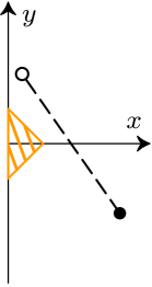
As a motivational example, let be the figure- graph (three edges emanating from a single vertex) with its usual path metric , and consider the space consisting of pairs of points of which are at least distance apart. A path in from to may be thought of as the motion of two particles (the first particle) and (the second particle) in , beginning at and , ending at and , and staying at least apart throughout their trajectories (see Figure 1). Here is assumed to be small relative to the lengths of the arms.


More formally, we define the ordered two-point -configuration space of a graph with path metric :
and the unordered two-point configuration space of :
The lack of in the unordered case will be explained shortly.
The product space may be endowed with various natural metrics, any of which is inherited by and . We focus our attention on the and metrics. Writing and for points , the and metrics on are defined:
In Figure 1, it is easy to see that there is a unique geodesic from to in the metric, obtained when the particles traverse their indicated paths at the appropriate relative speed.
Remark.
If is a tree not homeomorphic to an interval, the ordered two-point configuration space is not geodesically complete in the nor metric. To see this, let be a vertex of degree with and such that and lie on different edges adjacent to , both at equal distance from . By moving the second point slightly onto a third edge, we can obtain a path in from to of length arbitrarily close to , but there is no path of length in either metric. Therefore we replace by the geodesically complete space , which is a (-equivariant) deformation retract of and hence topologically equivalent to it (see Lemma 3).
Remark.
If is a tree with a vertex of degree , the unordered two-point configuration space is not geodesically complete in the metric. To see this, suppose that , , , and lie on different edges adjacent to , all equidistant from at distance . As above, there is a sequence of paths in with length approaching , but there is no path of length . On the other hand, is geodesically complete in the metric for any tree . The key difference is that the speed of travel is irrelevant in the metric; only the total distance traveled by the particles is important. Thus there is no penalty for choosing a motion which first keeps one particle fixed while the other moves to its destination, and then moves the remaining particle to its destination. This strategy eliminates any issues caused by collisions which could potentially occur when both particles move simultaneously.
Our main results give the values of , , and of for certain graphs .
Theorem 1.
Let be a star graph, with edges emanating from a single vertex, and let be the ordered two-point -configuration space of . Then
-
(1)
If , , for .
-
(2)
If , , for .
Theorem 2.
Let be a tree and let be the unordered two-point configuration space of . Then
-
(1)
If is homeomorphic to an interval, then .
-
(2)
If is the -graph, .
-
(3)
Otherwise, .
For a tree , the topological complexities of the configuration spaces and are well-known (see [6]); the lower bounds for follow from this and the fact that deformation retracts to (see Lemma 3). We show the upper bounds by constructing explicit geodesic motion planners. The general strategy for constructing geodesic motion planners on a metric space is to analyze the structure of the total cut locus, which we define as follows:
On the complement of , the geodesic is uniquely determined, and there is a well-defined map which sends a pair of points to the unique geodesic connecting them. If is a proper metric space, this map is continuous (see [1], Corollary I.3.13), yielding a GMPR on . Thus to construct a geodesic motion planner on a metric space , it suffices to find GMPRs over the total cut locus .
In the metric on , the only pairs of points in are those for which there is a path from the starting configuration to the ending configuration in which one particle does not move. Thus contains almost all of . In particular, the rule on does not contribute much to the geodesic motion planner, and so the proof of Theorem 2 still requires partitioning into the appropriate number of ENRs, on each of which there is a continuous choice of a geodesic. This is the content of Section 3.
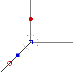
On the other hand, an essential part of the proof of the case of Theorem 1 is a careful analysis of . To illustrate the difficulties which may arise when determining the total cut locus, we offer a second example, depicted in Figure 2. Due to the condition that the particles must stay distance apart throughout their trajectories, the second (square) particle in Figure 2 must move away from its destination to let the first particle pass.


Observe that there is a second feasible path from to , in which the second particle moves into the right arm of the -graph and the first particle moves into the bottom; next the second particle moves through the vertex until both particles can travel directly to their destinations. Although this path appears almost obviously longer, note that in the limit, taken as the points and approach the vertex, the two paths have equal length. Thus it is important to carefully determine the geodesics based on the relative locations of and . In particular, we will see that most points of the total cut locus require an orientation switch, in which an empty arm is used to allow the particles to reconfigure (see Figure 4, right). When an orientation switch is necessary, there are two possible considerations: which particle will allow the other to pass, and which arms the particles will use to execute the orientation switch. These considerations are discussed in greater depth in Section 2.2.
Remark.
It is interesting to note, in the case such that is homeomorphic to an interval and is considered with the metric, that both the total cut locus and its complement are nonempty, yet there exists a single GMPR on the entirety of . This serves as a counterexample to the somewhat intuitive notion that, by definition of , a GMPR on should not be compatible with one on .
2. The proof of Theorem 1: Geodesic motion planning on
To begin, we exclusively consider the metric on . In Section 2.4 we make appropriate modifications to the case to establish the case. The main difficulty in the proof of the case of Theorem 1 is to determine the total cut locus of , so that geodesic motion planning rules (GMPRs) can be constructed and the upper bound on can be established. Before launching into this analysis, we formalize the lower bound in terms of .
Lemma 3.
Let be a tree and suppose that is not larger than the length of any edge. Then there is a (-equivariant) deformation retraction from to .
Proof.
Let with . If or is a vertex , move the other one along its edge to distance from . If and lie on the same edge, move them apart uniformly until they are at distance from one another. If this motion causes one of them to reach a vertex , stop it at the vertex and move the other one to distance from . If a vertex lies between and , move them apart with speed proportional to their distances to , until they are at distance from one another. ∎
The remainder of this section is dedicated to establishing the upper bounds on . We begin by introducing a planar representation of the configuration space which is convenient for depicting certain paths in . Consider , so that , , , and each lie on some open arm of the -graph. We define
We emphasize that the set depends on the points and , hence will change based on the locations of , , , and .
Consider particles and in the top arm of the -graph, in the right arm, and in the bottom arm (see Figure 3). In this example, consists of points such that is in the top or right arm, and is in the top or bottom arm.
The right side of Figure 3 depicts a representation of the set . The choice of representation is indicated by the directed arcs labeled and in the left image. These arcs define the meaning and orientation of the and axes in the right image. In this case, the -axis always indicates the position of the first particle, as follows: the negative -axis represents the negative distance from the vertex to the first particle, assuming that the first particle is in the top arm; the positive -axis represents the distance from the vertex to the first particle, assuming that the first particle is in the right arm. The negative (positive) -axis is similar; it always indicates distance for the second particle, with respect to the top (bottom) arm. The interior of the rectangular strip is forbidden; for any point inside, the distance between the particles is less than , hence the point is not an element of .
If the first particle enters the bottom arm, or if the second particle enters the right arm, the configuration of the particles ceases to be an element of , hence is not representable on the axes shown. Thus we sometimes refer to elements/subsets of as representable.


In the next sections, we rely primarily on geometric intuition to present the GMPRs, and we use the representation only as a visual aid to depict the geodesic between and . We show in Section 2.5 that the notion of representability can be used to formalize these intuitive statements. For example, by noting that the map taking to is an isometry, it is often convenient to argue the uniqueness of geodesics in by using the uniqueness of geodesics in the corresponding representation. As a related example, in the left side of Figure 3, it is clear that a geodesic path from to has the property that if the particles follow the geodesic, the first particle will not leave the top arm, and the second particle will not enter the top arm. We tacitly assume such statements in the following sections before verifying them in Section 2.5.
2.1. Geodesic motion planning on for the -graph
We begin our investigation in the case of arms, though the methods here generalize to higher values of . In this subsection, always refers to the -graph, and always refers to the -point ordered -configuration space of , considered with the metric.
We define the following partition of .
Definition 3.
We partition into the following subsets. In the notation below, a subscript indicates the exact number of arms which the points occupy; a superscript indicates whether the orientation of the initial configuration agrees with (“+”) or disagrees with (“-”) the orientation of the target configuration . In particular:
-
(1)
(resp. ) consists of points such that , , , all lie on a single arm of (vertex included), and such that the relative orientation of the starting points and agrees with (resp. disagrees with) that of and .
-
(2)
(resp. ) consists of points such that , , , all lie on exactly two arms of (vertex included), and such that the relative orientation of the starting points and agrees with (resp. disagrees with) that of and ; see Figure 4, left (resp. right).
- (3)


Proposition 4.
The sets , , and are disjoint from the total cut locus .
Proof of Proposition 4.
For points in and , there is a unique geodesic taking the direct path from to .
By the definition of , each of the three arms contains a point, hence two points must share one arm. By utilizing symmetries, we may assume that shares an arm with another point. Indeed, in the case that shares an arm with (resp. ), the argument follows from the case in which and (resp. ) share an arm, by the -symmetry swapping and . In case the two destination points and share an arm, the argument follows by reversing the geodesic path in the case that and share an arm. Thus we have three cases to consider: that shares an arm with , , or .
These three cases are depicted with their representations in Figures 3, 5, and 6, respectively. In each case the particles can move directly to their destinations and do not enter unused arms. We reiterate that this intuitive proof can be formalized using the notion of representability, first by showing that any geodesic from to must be representable (see Lemma 11), and then by observing that the representation map is an isometry, so that the unique geodesic between the representations of and corresponds to a unique geodesic between and . ∎


2.2. The total cut locus of
We turn our attention to the total cut locus of . By Proposition 4, the total cut locus is contained in . If , , any path from to must undergo an orientation switch, in which an empty arm is used to allow the particles to reconfigure; for example, an orientation switch is necessary for the configuration depicted in the right side of Figure 4. If is a star graph with arms, then any which requires an orientation switch is an element of the total cut locus, because one always needs to designate which empty arm is used for the orientation switch. In the case of the graph with arms, not all of is contained in . In particular, the arm used for the orientation switch is pre-determined by the relative locations of and , so is only in when there is not a preferred particle which moves onto the free arm to let the other pass. We will formalize these ideas now.
As there exists a GMPR on the complement of the total cut locus, the case of Theorem 1(a) is a consequence of the following:
Proposition 5.
There exists a GMPR on the total cut locus .
As , we first consider the spaces and separately.
Lemma 6.
The set is a subset of the total cut locus , and there exists a GMPR on .
Proof.
We assume that no point is farther from the vertex than , keeping in mind the possibility that . In case is farthest, there is a symmetry swapping the particles, and if either or is farthest, then and may be swapped and the geodesic path may be reversed.
For points in , an orientation switch is necessary, and there exist exactly two geodesics from to . In particular, order the arms clockwise, with arm at the top, and consider the ordering mod . If the points all lie on arm , there is a unique geodesic for which the second particle uses arm for the orientation switch, for each .
To see that there exist no other geodesics, consider the configuration depicted in Figure 7. According to the definition of , the only representable points are those for which both particles are in the top arm. There are two natural ways to extend the representable region, depicted either in the left or the center of Figure 7. In either case, the unique geodesic has the representation depicted on the right (although the positive axes have different meaning depending on the choice). If a path is not representable in either of these two representations, then at some time during the trajectory, both particles lie either in the open right arm or the open bottom arm. Such a path is non-minimizing (see the displayed statement in the proof of Lemma 11).


Now a GMPR on can be defined: choose the geodesic for which the second particle uses arm (so that the first particle uses arm ) for the orientation switch. ∎
All points of require orientation switches, but not all points are in the total cut locus. Assume momentarily that lies on the top arm, that none of , , or lies above , and that points not on the top arm lie on the bottom arm. Then there are three possible permutations of the and , from top to bottom: , , and (it is possible that or or ). Other permutations beginning with have agreeing orientation and are not elements of .
Considering cases dictated by the three possible permutations, as well as the number of and which lie on each arm, we see that there is a unique geodesic in the following cases:
-
if the closed top arm (i.e. including the vertex) contains exactly three of the and , or if the closed bottom arm contains exactly three of the and , then a geodesic is uniquely determined. See Figure 8 (left and center) for two possible configurations – other possibilities permute the and but have similar behavior.
-
if and share the open top arm and and share the open bottom arm, there exists a unique geodesic (see Figure 8, right).
Note that in the case of arms, all such points lie in the total cut locus, because an arm choice is necessary – see Section 2.3 for further discussion.


Similar arguments may be made in the cases which do not adhere to our specific assumptions. For example, if lies above , there is a symmetry swapping the particles. If either or lie above , there is a symmetry swapping the initial configuration with the final configuration, and the unique geodesic is the reversed geodesic from the above case. Finally, the same arguments can be made with respect to any of the three arms.
Thus it remains to consider the case in which and share an open arm, and and share a different open arm. As such, we define
A point of is depicted in Figure 9, left. For , every path from to must undergo an orientation switch, and paths from to may be distinguished based on which particle moves through the vertex first for the orientation switch (i.e. to enter the empty arm so that the other particle may pass). We refer to a path such that the th particle passes through the vertex first as a path of type .
We claim that for each particle , there exists a unique length-minimizing type path. Indeed, any length-minimizing type path must pass through the point depicted in Figure 9, right. Now and are in the complement of the total cut locus by Proposition 4, so there are unique geodesics connecting to and to . Their concatenation is the unique length-minimizing type path from to . Similarly, there is a unique length-minimizing type path from to .


For at least one value of , the unique length-minimizing type path is the minimal geodesic from to . Occasionally these two paths have equal length, in which case the point is in the total cut locus. Such points are characterized by a certain algebraic condition relating the distances from , , , and to the vertex, but it is not necessary to determine this condition explicitly. Instead, we simply define
and . We have shown that is disjoint from the total cut locus , despite the fact that orientation switches are needed for all points of . However, with arms, every orientation switch requires a choice of empty arm to use for the switch, so is part of the total cut locus for star graphs (see Section 2.3).
Lemma 7.
There exists a GMPR on .
Proof.
We define the GMPR on so that the particle which enters arm for the orientation switch is the particle which begins on arm , i.e. the arm adjacent to in the clockwise direction. ∎
Finally, we prove Proposition 5, that there exists a GMPR on the total cut locus .
Proof of Proposition 5.
We have exhibited GMPRs on and on , so it remains to show that these are compatible on the union . In particular, we must check that the GMPRs agree at the points of which are limit points of : these are points such that lie at the vertex, or lie at the vertex.


We consider a fixed limit point ; without loss of generality, we assume that and lie on the top arm and that and lie on the vertex; see Figure 10. Then the GMPR would choose the geodesic for which the second particle moves into the right arm and the first particle moves into the bottom arm to let the second particle pass into the top arm. Consider a sequence of points approaching . If for some , and lie in the bottom arm, then the GMPR chooses the geodesic for which the second particle moves into the empty (right) arm and the first moves into the bottom arm. If for some , and lie in the right arm, then the GMPR chooses the geodesic for which the first particle enters the empty (bottom) arm (and if necessary, the second particle moves within the right arm to the boundary of the -ball around the vertex) to let the second particle pass. Thus in the limit , the limiting path is exactly the chosen geodesic at . ∎
Remark.
To prove Theorem 1(a) in the case we exhibited two GMPRs: one on the total cut locus and one on its complement . Note that no GMPR on either or is compatible with a GMPR on .
2.3. Geodesic motion planning on for star graphs
We are now equipped to study the geodesic motion planning problem on a star graph , with arms emanating from a single vertex. The techniques are similar to those for the case , and many of the results from the previous section will be used.
Let be the -point ordered -configuration space of . In addition to the subsets of defined in Defintion 3, we consider the set consisting of points such that there exist four arms of occupied. Given , we say that a path from is type if the th particle passes through the vertex first. Recall that type paths were defined in Section 2.2 for elements of ; however, for , the particle which moves through the vertex first does so to allow the other to pass, whereas for , the particle which moves through the vertex first may travel directly to its destination.
For each particle , there is a unique length-minimizing path among those of type . At least one of these is a geodesic. As in the case of , we define:
and (see Figure 11). Thus by definition, .


Recall the discussion prior to Lemma 7: with arms, belongs to the total cut locus, since any orientation switch requires a choice of empty arm, and, unlike the situation on the -graph, there are now multiple such choices.
Now the sets and , together with , partition . The following result establishes three GMPRs on .
Proposition 8.
Let be a star graph with arms, . The complement of the total cut locus is given by , and there exist GMPRs on
-
(1)
-
(2)
-
(3)
,
hence .
We compare to the situation of the -graph. There, the sets and do not exist, the complement of the total cut locus is , and we exhibited a GMPR on . With more than three arms, one cannot define compatible GMPRs on and . So we instead show that the GMPR on is compatible with that on the complement of the total cut locus, that admits a GMPR compatible with that on , and that admits a GMPR.
Proof.
We first remark that are in the complement of the total cut locus by definition, and is in the complement of the total cut locus by Proposition 4 and because geodesics do not enter unused arms unless an orientation switch is necessary (this can be formalized in the same manner as Lemma 11).
Rule 1. As the complement of the total cut locus, there is a GMPR on . The GMPR on can be defined in the case of arms: designate arm for the orientation switch, where is the smallest index such that arm is empty but arm is occupied, and use the particle beginning on arm for the switch.
To show that the GMPR on is compatible with that of the complement of the total cut locus, we can show that the closures of the sets are disjoint.
The closure of is contained in . If a limit point of uses only two arms, then one of or must lie at the vertex, hence . Finally, is closed.
Rule 2. To motion plan on , observe that is a union of finitely many disjoint open sets, defined by indicating which arms contain which particles. It is enough to motion plan on one of these sets, and the GMPR may be defined simply by always letting the first particle through the vertex first.
The GMPR on is defined in Lemma 6; the same argument holds verbatim for star graphs with arms.
Now is closed, and limit points of occupy at least two arms, so . Thus the GMPRs are compatible on the union.
Rule 3. Finally, for points , the particle which must move first for the orientation switch is pre-determined, and so we only must choose which arm is used for the switch. We define the GMPR to use the empty arm of lowest index. ∎
With the analysis complete, we now turn our attention to the metric on .
2.4. The metric on and the proof of Theorem 1
The -case of Theorem 1 follows from Propositions 5 and 8, and so it remains to consider the -case. To distinguish between geodesics in various metrics, we will use the terminology “-geodesic” to refer to a geodesic in .
Remark.
Because the and metrics induce the same topology on , the induced compact-open topologies on the path space are equivalent. In particular, if , and if , then is continuous in the -induced compact-open topology on if and only if is continuous in the -induced compact-open topology on . Thus it is not necessary to distinguish notions of continuity when considering geodesics in different metrics.
To adapt the argument to , the general idea is as follows: we will use essentially the same partition as in the case, apart from small modifications to the decompositions of and . In particular, the sets , , , and , which were previously defined in terms of the metric, will be redefined in terms of the metric. The actual GMPRs, which by definition map a point to an -geodesic from to , will always follow local -geodesics; that is, paths which locally, but perhaps not globally, minimize -distance.
In particular, we recall that most points lie in the total cut locus: unless one particle stays fixed throughout a minimizing trajectory, one can perturb any -length-minimizing path, by changing the speed of one of the particles, without changing the -length. Even pausing one particle does not penalize the -length; as long as a motion from to does not involve unnecessary backtracking, the motion corresponds to an -geodesic. It follows that if an -geodesic follows a direct path from to , as is the case when , then is also an -geodesic. More generally, we have the following.
Lemma 9.
Let and let be an -geodesic from to . Then is an -geodesic.
Proof.
For points , the uniquely-determined -geodesic moves directly to , hence is an -geodesic. For points , is also uniquely determined, and although such geodesics may contain a brief motion which moves a particle farther from its destination, such motions are strictly necessary. To see this, observe in Figure 2 that any -geodesic must pass through the points and depicted, respectively, in the center and right images, and so the length of any -geodesic from to is equal to the sum . The -geodesic also passes through and . Moreover, the three points , , and all lie in , so is the concatenation of the three uniquely-determined -geodesics connecting these points, each of which is also an -geodesic. Thus also has -length and hence is an -geodesic.
Similar arguments apply to points . For such , there is an -geodesic from to corresponding to each choice of arm(s) used for the orientation switch. However, once the arm choices are fixed, one may again determine point(s) through which any -geodesic must pass, and similar arguments may be made. ∎
Lemma 9 establishes that all -geodesics are -geodesics, except perhaps -geodesics from to for points . In the next example we give explicit points of and of such that Lemma 9 fails. We recall that for , a path from to is type if the th particle passes through the vertex first. For , and for each particle and empty arm , there is a unique -length minimizing path among those of type using arm for the orientation switch. For , no orientation switch is necessary, but for each particle , there is a unique type -length minimizing path.
Example 1.
Let be a star graph with arms with . Consider , such that , , , and (see Figure 12, left); here represents distance from the vertex. Let represent any path which achieves the minimum -length among those of type . Let represent the length of . Then
In particular, the unique -geodesic is not an -geodesic, but the path , which is not an -geodesic but does minimize -length among type paths, is an -geodesic. A similar phenomenon occurs for with , , , and (see Figure 12, right).


We reiterate the intuitive motion planning strategy in the -case: if has the property that all -minimizing geodesics are of type , then choose an -geodesic (which may not be an -geodesic). Now we will formalize these rules, defined on the following sets:
Note that and are defined in the same manner as and , with “-geodesic” in place of “-geodesic”. Also analogous to the case, we define and .
We define the following GMPRs on these new sets. We note that, qualitatively, all rules exactly match those in the case, as presented in Sections 2.2 and 2.3; the only difference is that the actual paths are only locally -length minimizing and may not be -geodesics.
Lemma 10.
There exist GMPRs on the sets , , , and .
Proof.
Recall that represents any path which achieves the minimum -length among those of type . For , is unique. For , we also use the notation to refer to the unique -length minimizing path from to among those type paths which use leg for the orientation switch.
On , there are -geodesics of type and ; among them we choose .
On , there are only -geodesics of one type ; among them we choose .
On , there are -geodesics of type and ; among them we choose , where is the smallest index such that arm is empty but arm is occupied, and is the particle on arm .
On , there are only -geodesics of one type ; among them we choose , where is the unused arm of least index. ∎
When studying compatibility issues in the following proof of Theorem 1, it is important to note that for and , the path chosen by the above rule is the unique -geodesic, which is an -geodesic by Lemma 9. Also by Lemma 9, all geodesics on are -geodesics, so we define the GMPRs on these sets to use the same geodesics as used in the case.
We are now prepared to formalize the proof of Theorem 1 in both the and cases.
Proof of Theorem 1.
All lower bounds on follow from the known values of , together with Lemma 3. The upper bounds for the case for parts (a) and (b) follow, respectively, from Propositions 5 and 8. In the case, it remains to study the compatibility of the GMPRs above. We emphasize that the rules are qualitatively identical to those in the case, so there are only a few compatibility issues to check.
(a) Let . We claim that there exist two GMPRs, using the same partition as in the case, except for the above replacements. In particular, there are rules on the sets:
-
-
.
The rules on and have the same qualitative behavior as in the case; the verification that these are compatible is the same as in the proof of Proposition 5.
The GMPR on uses the unique -geodesic and is well-defined by Lemma 9. We only must show that the GMPR on is compatible with that on . Note that this was not an issue in the case as all sets were in the complement of the total cut locus.
To show compatibility, first observe that is closed, and limit points of are contained in . A limit point of may be an element of , but it cannot be an element of since at least one of , , , or lie at the vertex. Since the GMPR on uses the unique -geodesic from to (see the comment below the proof of Lemma 10), as does the rule on , the rules are compatible.
(b) Let be a star graph with arms. We claim that there are rules on the sets:
-
-
-
.
Once again, the second and third rules have the same qualitative behavior as in the case; the verification that these are compatible is the same as in the proof of Proposition 8.
For the first rule, the GMPRs on and are defined above, and the GMPR on uses the unique -geodesic. Furthermore, and do not share any limit points (analogous to the proof of Proposition 8). Thus we only must show that the GMPR on is compatible with that on . Note that this was not an issue in the case as all sets were in the complement of the total cut locus.
Suppose that is a limit point of . We claim that if a point is sufficiently close to , then is in the complement of the total cut locus. This would establish that the GMPRs at and both use unique -geodesics, hence the rules are compatible.
Observe that at least one (and at most two) of , , , and lie at the vertex; we assume is at the vertex, possibly shared with . The GMPR indicates that should use the unique -geodesic from to ; this geodesic has the property that the first particle will immediately move down the arm which contains its destination point (there is nothing to be gained by waiting at the vertex nor by moving onto another arm). Thus may be considered a type path, since the first particle moves through the vertex before the second particle. Any type path (i.e. a path such that the first particle moves onto an empty arm to allow the second particle to go through the vertex “first”) is strictly longer. Therefore a sufficiently nearby point will also have the property that any - or -geodesic is type , hence the -geodesic is unique. ∎
2.5. Representations of configurations in
In previous sections we regularly appealed to intuition regarding the existence and uniqueness of geodesics in various cases. Here we formalize one statement using the notion of representability; similar arguments may be made for all such statements.
Lemma 11.
If , then every geodesic from to is representable.
Proof.
We reference Figure 3 in the following argument.
Consider any path from to , and suppose some portion of is not representable. In particular, let be some interval such that each is representable, but no , is representable. Thus at each time , one of the two particles is at the vertex of the -graph, and so is represented on one of the four branches of the axes in the right image of Figure 3. We will first show:
Indeed, the geodesic in between two points and , whose representations lie on the same axis branch, is representable: the representation is an isometry and the geodesic in the representation is the straight line segment along that axis. Since is not representable, it is not minimizing.
Now observe that if is on the positive -axis, then also must be; since if the second particle is on the bottom arm when the first particle enters the bottom axis, it must stay there until the first particle leaves. The same argument applies to the positive -axis.
The remaining option is that one point (we assume it is ) is represented on the negative -axis, and is represented on the negative -axis. In this situation, the path undergoes an orientation switch. In this case, the second particle enters the right arm while the first particle is on the top arm, then the first particle enters the bottom arm, then the second particle re-enters the top arm, and the first particle moves back to the vertex. However, this path is exactly the same length as the corresponding path in which the roles of the bottom and right arms are swapped in the previous sentence. This latter path is representable, so we may redefine on with this representable path, without changing its length. In this way, every non-representable path is the same length as some representable path. However, there is a unique representable geodesic connecting and , and it does not involve any orientation switches, so it is not the same length as any non-representable path. ∎
Together with the fact that the representation map is an isometry, Lemma 11 is used to verify that elements of are not in the total cut locus of .
When , it is possible that an orientation switch is necessary, and it is possible that some non-representable path and its representable replacement are actually geodesics. This was the case for cut locus points in and . Nevertheless, in these cases the same argument may be used to show that these geodesics are unique among those of certain types; e.g., among geodesics of type using arm for an orientation switch.
3. The proof of Theorem 2: Geodesic motion planning on
We now turn our attention to the proof of Theorem 2. In case is homeomorphic to an interval, a single geodesic motion planning rule (GMPR) may be defined explicitly on . This establishes part (a) of Theorem 2. For the remainder of this section, refers to a tree which is not homeomorphic to an interval.
The main accomplishment is to partition into three ENRs (two for the graph), on each of which there is a continuous choice of a geodesic from the initial configuration to the ending configuration.
We begin with a definition and elementary proposition.
Definition 4.
Let be a subset of a tree . The convex hull of is the minimal connected subtree of containing ; equivalently, it is the union of (the images of) all minimizing geodesics connecting points of .
If are any three points on a tree , then the image of the geodesic path from to is contained in the union of the paths from to and to . Therefore may equivalently be defined as the union of the images of all geodesic paths from one fixed point of to all other points of . When is a set of four points on , is the union of three paths emanating from a single point, and so we have the following:
Proposition 12.
If is a set of four points on a tree , then must be one of the following five types, pictured in Figure 13.
-
.
One point of is at a vertex, from which paths to the other three are disjoint.
-
.
There is a vertex from which there are disjoint paths to three of the points of , and the fourth point of lies in the interior of one of these paths.
-
.
There is a vertex from which paths to all four points are disjoint.
-
.
There are two vertices, from each of which there are disjoint paths to two points of , and these four paths are also disjoint from the path between the two vertices.
-
.
Two points of lie inside the path connecting the other two.
We number the degree-1 vertices of from to in clockwise order around the tree. In Figure 14, we depict a tree with numbered vertices, and a selection of four points on it of each of our five types.
If is an edge emanating from a vertex , let denote the path component of containing . For example, if is the degree-4 vertex in the graph in Figure 14, and is the edge going down and to the left from it, then contains all points between and the degree-1 vertices labeled 1, 2, and 3. Another example is when is the vertex where arms 5 and 6 meet, and is the edge coming down from it; in this case contains all points between and the degree-1 vertices labeled 1, 2, 3, 4, 7, and 8. We assign to the edge or to the point on this edge the smallest of these arm numbers. Note that this depends on as well as . As an example, if consists of points on the arms going out to 5 and 6, a point at the vertex where those arms meet, and a point on the arm going out to 7 and 8, then the arm number for the latter point is 1, not 7.
We will be considering moving from to , with . We will depict and by black dots (B), and and by white (open) dots (W). It is possible that or might coincide with or , and so we also consider the possibility that in the two dots on an edge coincide (and have different colors), and similarly for two adjacent dots on an diagram.
We subdivide the diagrams into three types:
-
.
There are one or more vertices of the graph in the interior of the , the endpoint with the smaller arm number contains a white dot, and the endpoint with the larger arm number contains a black dot.
-
.
There are one or more vertices of the graph in the interior of the , the endpoint with the smaller arm number contains a black dot, and the endpoint with the larger arm number contains a white dot.
-
.
All other diagrams, so those containing no vertices in the interior and those that do not contain oppositely-colored dots at their endpoints.
Proposition 13.
Let be a tree. Partition into three sets as follows. We use the dot color conventions as described above.
-
.
is of type or of type or such that the arm with smallest arm number contains a black dot, and, for , the arm with two dots on it contains dots of the same color.
-
.
is of type or of type or such that the arm with smallest arm number contains a white dot, and, for , the arm with two dots on it contains dots of the same color.
-
.
Everything else. Thus is of type , , , or such that the arm with two dots on it contains dots of each color.
There is a GMPR on each of , , and .
Remark.
This implies that , and hence implies Theorem 2 when is not the graph, since when .
Proof of Proposition 13.
Figures 15 and 16 depict the cases in and , respectively. By placing the dot in the inside of an arm at the vertex, we obtain the cases of and , respectively. The numbers 1, 2, and 3 indicate the relative order (smallest to largest) of arm numbers associated to the three edges emanating from the vertex . The path that we select is the one that first does uniform motion from the black dot to the white dot indicated by the arrows in the diagram. It is followed immediately by uniform motion from the other black dot to the other white dot. Our uniform motions are always parametrized proportionally to arc length. One can see from the diagrams that collision is avoided. The analogous motion is performed for the associated diagram. These geodesic paths clearly vary continuously with .
After possibly reorienting, the and diagrams are in the order either BBWW or BWBW, with adjacent B and W possibly at the same position. We choose the path which first moves from the rightmost B uniformly to the rightmost W, followed immediately by uniform motion from the other B to the other W.
For each of the six diagrams of Figures 15 and 16, there are two ways that a white dot and black dot could both approach the vertex, having an diagram of BBWW form as the limiting diagram. In every case, one of those will have as the limiting motion the geodesic just described for the BBWW diagram, while the other will not be in the same set as the diagram that approached it, and so we do not have to worry about compatibility. For example, in the first diagram of Figure 15, if the inner white dot and dot 1 approach the vertex, the limiting diagram has motion of the first type just described, while if the inner white dot and dot 3 approach the vertex, the limiting diagram is of the second type because the endpoint with the smaller number has a black dot, as is the case for diagrams. The thing that makes this work is that the Figure 15 diagrams have the motion between outside dots increasing the arm number (, , and , respectively), which corresponds to the motion between outside dots of diagrams. A similar, reversed discussion holds for Figure 16 diagrams.
This completes the proof that we have a GMPR on and . The argument for which follows is rather similar.
For the diagrams of the form BWWB and WBBW, we use simultaneous uniform motion from the B to the adjacent W. For those of the form BBWW and BWBW (which are all in a single edge), we move from the rightmost B first.
For diagrams, we first move uniformly from the black dot with smallest arm number to the white dot with smallest arm number, and then uniformly from the other black dot to the other white dot. As one or two (differently colored) dots approach the vertex, a or or diagram is obtained. Since these are not in , we need not worry about compatibility. A similar rule is used for an diagram in which the arms emanating from each of the vertices and contain dots of the same color; we first move uniformly from the black dot with smallest arm number to the white dot with smallest arm number, and then uniformly between the other two dots. The limit as one or two (differently colored) dots approach a vertex is either a diagram in or or an or diagram, and so again compatibility is not an issue.
For the diagrams in , we can use simultaneous uniform motion between the two dots on one arm, and between the dots on the other two arms, always from black to white, or course. There is no risk of collision. If one of the dots which are unaccompanied on their arm approaches the vertex, we obtain either an diagram with compatible simultaneous motion or an or diagram. If one or both of the dots on the doubly-occupied arm approach the vertex, the limiting diagram is not in , so compatibility is not an issue. Similarly for diagrams with dots of different colors on each of the two arms emanating from each vertex, move simultaneously and uniformly between the dots on the two arms emanating from each vertex. The limit as one or two of the dots approach their vertex is either a or diagram in with compatible motion or else an diagram not in .
This completes the GMPR on and thus completes the proof of the theorem. ∎
The following result implies Theorem 2 when is the graph, since .
Proposition 14.
If is the graph, then can be partitioned into two ENRs with a GMPR on each.
Proof.
There are no or diagrams. We can describe all the diagrams in a rotation-invariant way. The diagrams and one diagram are placed into the two sets and as suggested in Figure 17. The depiction of contiguous white and black dots means that they can appear in either order or at the same point, and in the last diagram they may appear anywhere between the two end points.
All diagrams are placed in , and all diagrams except the ones of the type illustrated in Figure 17 are placed in . The GMPR is simultaneous uniform linear motion on all the diagrams and the first two diagrams in Figure 17. For the diagrams, there is only one way that this can be done without collision, while for the two in Figure 17, it is between the two bottom dots and between the two top dots. For diagrams and in Figure 17 and the diagrams obtained from them by moving the inner point to the vertex, call the point moving with the arrow “point 1” and the point moving between the other two dots “point 2.” We use uniform linear motion for point 1, while point 2 moves uniformly from the black dot to the vertex, and then uniformly (at a usually different rate) from the vertex to the white dot in such a way that for Diagram A (resp. B) it arrives at the vertex after (resp. before) the first dot.
Let (resp. ) denote the distance from the vertex of the black (resp. white) dot involved in the uniform motion with the arrow, and (resp. ) the distance from the vertex of the other black (resp. white) dot. Noting that point 1 hits the vertex when , we choose to have point 2 hit the vertex when in Diagram A, and when in Diagram B. This gives the appropriate values of if or , implying uniform linear motion on the diagrams. It is important to note, too, that the limiting motion as (resp. ) approaches 0 in Diagram A (resp. B) is the simultaneous uniform linear motion of the diagram in .
Since most of the diagrams are in , while most of the diagrams are in , only a small amount of checking of compatibility of the motion in an diagram that is a limit of diagrams in the same is required, and this is easily done. The only diagram that is a limit of diagrams in is in . Each of the first three diagrams in Figure 17 can approach an diagram with an impossible motion of moving from an outer black dot to an outer white dot, but the arrangement of black and white in these is opposite to the diagram in Figure 17, so that limiting diagram is in . ∎
References
- [1] M.R.Bridson and A.Haefliger, Metric Spaces of Non-Positive Curvature, Grundlehren der mathematischen Wissenschaften Vol. 319, Springer-Verlag (1999).
- [2] D.M.Davis, An n-dimensional Klein bottle, Proc. Roy. Soc. Edinburgh Sect. A 149 (2019) 1207–1221.
- [3] D.M.Davis, Geodesics in the configuration spaces of two points in , arXiv:2001.00850.
- [4] D.M.Davis and D.Recio-Mitter, Geodesic complexity of -dimensional Klein bottles, arXiv:1912.07411.
- [5] M.Farber, Topological complexity of motion planning, Discr. Comp. Geom. 29 (2003) 211–221.
- [6] M.Farber, Collision-free motion planning on graphs, in Algorithmic Foundations of Robotics VI, Springer (2005) 123–128.
- [7] R.Ghrist, Configuration spaces and braid groups on graphs in robotics, AMS/IP Studies Advanced Math 24 (2001) 29–40.
- [8] D.Recio-Mitter, Geodesic complexity of motion planning, arXiv:2002.07693.