\TitleFontHigh Frequency, High Accuracy Pointing onboard Nanosats using Neuromorphic Event Sensing and Piezoelectric Actuation
Abstract
As satellites become smaller, the ability to maintain stable pointing decreases as external forces acting on the satellite come into play. At the same time, reaction wheels used in the attitude determination and control system (ADCS) introduce high frequency jitter which can disrupt pointing stability. For space domain awareness (SDA) tasks that track objects tens of thousands of kilometres away, the pointing accuracy offered by current nanosats, typically in the range of 10 to 100 arcseconds, is not sufficient. In this work, we develop a novel payload that utilises a neuromorphic event sensor – for high frequency and highly accurate relative attitude estimation – paired in a closed loop with a piezoelectric stage – for active attitude corrections – to provide highly stable sensor-specific pointing. Event sensors are especially suited for space applications due to their desirable characteristics of low power consumption, asynchronous operation, and high dynamic range. We use the event sensor to first estimate a reference background star field from which instantaneous relative attitude is estimated at high frequency. The piezoelectric stage works in a closed control loop with the event sensor to perform attitude corrections based on the discrepancy between the current and desired attitude. Results in a controlled setting show that we can achieve a pointing accuracy in the range of 1-5 arcseconds using our novel payload at an operating frequency of up to 50Hz using a prototype built from commercial-off-the-shelf components. Additional results and video demos can be found in the accompanying repository111 https://www.yasirlatif.info/ultrafinestabilisation online.
1 Introduction
Many commercially important space-based applications require precise control of spacecraft attitude. This includes applications that require consistent pointing of onboard sensors towards Resident Space Objects (RSOs), regions in a distant orbit or on the Earth’s surface. Precise pointing plays a critical role when the imaging sensor needs to be exposed for a long duration – ten of seconds to minutes – to capture enough reflected light from a distant RSO. Any pointing errors in the spacecraft during this exposure time cause the precious photons from the RSO to be spread over multiple pixels (Fig. 1 (left)), reducing the Signal to Noise Ratio (SNR) as well as the probability of detection. Precise stabilisation can help focus the light on a much smaller region within the imaging sensor (Fig. 1 (right)). Such stabilisation becomes mission critical when the main mission sensor experiences high frequency perturbations that can not be characterised by the sensor due to its low sampling rate. Therefore, there is a need for a a higher sampling rate sensor that can characterise such perturbations.


Event sensors [6] offer a unique sensing modality that operates at high sampling rates, enabling characterisation of high-frequency perturbations. Compared to conventional cameras used on-board that operate in the 1-30Hz sampling rate (due to size, weight and power constraints) event cameras can sense changes in illumination asynchronously at 1MHz with lower power requirements while providing higher dynamic range. This combination provides a unique opportunity to use event sensors for on-board perturbation characterisation. Fig. 2 provides a visualisation of events during a 1 second window when observing at a star-field under perturbations. Streaks in the Fig. 2a and 2b correspond to stars. Perturbations around a mean position can be observed even at such a small timescale (1 second). The event sensors generates high-frequency detection of the stars’ positions on the sensor (Fig. 2c), which can be used to rapidly detect any deviations from the desired pointing direction using the stars as a fixed reference.
Using the high frequency sensing capabilities as the cornerstone, we design a payload that provides stable pointing over the exposure duration of the imaging sensor. Instead of relying on the ADCS to manoeuvre the whole space craft, we show that pointing errors can be reduced by stabilising the mission sensor independently using an additional sensor – an event sensor – for standalone “ultra-fine” attitude estimation. We pair the low sampling rate (1-30Hz) mission sensor with a high sampling rate (kHz) event sensor to enable high frequency characterisation of the perturbations experienced by the satellite. The proposed payload rapidly and accurately estimates the deviation from the required pointing attitude. Perception alone, however, can not provide the pointing stabilisation since software based post-processing of the main mission sensor will be rate limited by its sampling rate. Therefore, a physical actuation mechanism – a micromotion stage – is employed to keep the main mission sensor pointed towards the desired attitude. This is the second part of our contribution. We refer to this mode of attitude estimation, where the residual correction from a desired attitude is computed via an additional sensors, as “ultra-fine attitude estimation” and the resulting attitude correct as “ultra-fine pointing stabilisation”.


In this paper, we present the design, algorithms and performance of a novel ultra-fine attitude estimation payload that takes advantage of the event-based neuromorphic sensor to provide ultra-fine attitude estimation for a co-located imaging sensor. The novelty of the proposed system comes from incorporating an event sensor for high frequency perception in the active stabilisation loop. This is combined with a piezoelectric motion stage, capable of providing repeatable motion in the m range, to execute high frequency corrections, together providing ultra-fine pointing stabilisation. The rest of the paper is organised as follows: Sec. 2 presents on overview of the prior art towards attitude estimation. Our system design is presented in Sec. 3 and the developed algorithms in Sec. 4. Evaluation of the system and performance results are presented in Sec 5.
2 Related Work
State-of-the-art commercial nanosatellite Attitude Determination and Control Systems (ADCS) claim a 1- pointing precision in the order of tens of arcseconds (see Tab. 2). These ADCS solutions aim to stabilise the entire spacecraft and are prone to several sources of errors from actuation jitter, vibration of reaction wheels, control system update rate and latency, as well as external factors such as atmospheric drag. The module presented in work works independently of the ADCS to provide more precise attitude estimation and correction.
| Manufacturer | Model | Mass (g) | Accuracy | |
| Sampling rate (Hz) | C/B-sight (arcseconds) | |||
| Adcole Space | MAI-SS | 170 | 5.7 / 27 | 4 |
| Blue Canyon Technologies | Standard NST | 350 | 6 / 40 | 5 |
| CubeSpace | CubeStar | 55 | 77 / 220 | 1 |
| Hyperion Technologies | ST200 | 42 | 30 / 200 | 5 |
| ST400 | 280 | 10 / 120 | 5 | |
| Jena-Optronik | Astro APS | 2000 | 1 / 8 | 16 |
| Astro CL | 280 | 6 / 35 | 10 | |
| NewSpace Systems | NSGY-001 | 100 | 180 / 720 | 1 |
| Sinclair Interplanetary | ST-16RT2 | 185 | 5 / 55 | 2 |
| Sodern | Auriga-CP | 205 | 11 / 69 | 10 |
| Hydra-CP | 1400 | 3.4 / 27 | 10 |
Event sensors have recently been applied to space applications where they have been used for tasks such as domain adaption [8], SSA [4] and object detection in space [1]. The asynchronous nature of the event stream has also been taken into account to develop an asynchronous Kalman filter for star tracking using ground-based telescopes [10]. Our proposal focuses on using the event sensor in an active stabilisation scenario, where the event sensors acts as an external source of information, alongside the main mission sensor for SSA. Such dual stabilisation has been successfully demonstrated in the ASTERIA mission [12] using a combination of a CMOS sensor, used both for imaging as well as stabilisation, and a piezoelectric actuator for stabilisation. However, such a system can only compute the stabilisation corrections at the sampling rate of the CMOS sensor and will not be able to detect higher frequency perturbations. Our proposal improves on their system by incorporating an additional event sensor and providing faster and more accurate stabilisation. The use of an additional sensor for attitude estimation task allows the CMOS sensor to focus solely on the task at hand of capturing the photons from the distant object of interest. From the perspective of the imaging sensor, this stabilisation is transparent.
3 System Design


The operating context of the proposed payload is presented in Fig. 3. Background stars form a fixed reference against which instantaneous positions of the event sensor can be computed. The event sensor computes ultra-fine attitude at high frequency using this fixed reference. Discrepancy between the estimated and desired attitude is then minimised by driving a micromotion piezoelectric stage to provide high-accuracy pointing towards the desired Resident Space Object (RSO). The ADCS provides fine-attitude control while the ultra-fine adjustments are carried out using the proposed payload (marked in red) to reduce residual deviations from the required pointing direction. Fig. 4 depicts the high level architecture of the proposed payload designed to provide ultra-fine pointing stabilisation. The relationship between the onboard ADCS and the proposed module is also depicted in both. The ADCS provides fine attitude estimation and needs to manoeuvre the whole spacecraft to achieve pointing. The proposed payload sits within the body of the spacecraft and within the influence of the ADCS (as shown by the outer dotted region in Fig. 4). However, the task of the proposed module is to correct residual pointing errors in the system by employing its own perception (via the event-sensor) and actuation (using the piezoelectric motion stage) mechanisms. Light from the telescope is focused on the two sensors: the event-sensor and the optical CMOS sensor which is responsible for imaging the RSO of interest. As both sensors are co-located on the piezoelectric motion stage, active stabilisation of the event sensor via the piezoelectric motion stage provides stabilisation for both sensor. This is how the proposed payload achieves stabilisation for the main mission (CMOS) sensor.
The onboard computer of the module receives data from the event sensor alongside the information about the desired attitude that needs to maintained during the image capture manoeuvre. Algorithms combine these pieces of information, compute the ultra-precise attitude of the sensor package, and generate motion commands for the piezoelectric stage, completing the action-perception loop and providing ultra-precise control. As part of the design, the optical sensor does not contribute to the stabilisation loop as it is the primary sensor for observations focuses solely on that task.
3.1 Hardware
In the section, we outline various hardware component of the payload, their main responsibility and how they are connected to other components.
Event Sensor Event sensors offer a novel sensing modality in the space domain. Unlike a conventional imaging sensor which captures an image at regular intervals, event-based sensing generates asynchronous “events” independently at pixels where the observed brightness changes. An event contains information about the pixel location, the direction of the observed intensity change and microsecond resolution timestamp of when the intensity change was observed. In the context of Space Situational Awareness (SSA), the scene is sparsely lit with vast swaths of black space and a few intermittent bright spots representing the stars. A conventional camera will spend energy in such a setting on repeatedly capturing the same region. Event-based sensors, in contrast, only generate events when intensity change is detected, either in the scene or induced by ego motion of the satellite. This leads to a smaller computation cost for downstream algorithms. Event sensors are also well-suited to space based space observations as they offer a higher dynamic range compared to CMOS sensors, enabling operation in conditions where the CMOS sensors would either be over- or under-exposed, leading to a smaller sun exclusion angle.
Commercial off the shelf event sensors have made remarkable progress in terms of the number of pixels on the sensor as well as the reduction in the physical size of the sensor. Fundamental change in CMOS technology have allowed significant reduction in noise by stacking the light receiving and the processing circuitry on top of each other, leading to a smaller footprint for the sensor and a larger fill-in area. All have these advances have made event sensor more appealing to the task of SSA.
Piezoelectric micromotion stage To provide active stabilisation, the main mission sensor needs to be physically moved to make attitude corrections. This motion is generated by controlling a micromotion stage containing a piezoelectric motor as the actuator. Piezoelectric based motion mechanisms allow precise and repeatable motion execution.
Two types of micromotion stages are found in practice: “Stepper” mechanism, where the micromotion of the piezoelectric component allows the mechanism to move a certain distance each time a voltage is applied. Such stages can hold their position without the need for additional power and do not need a homing mechanism, allowing the stage to carry out arbitrary motion sequences without the need to return to a known position (origin) between each motion step. However, stepper mechanisms tend to be comparatively slower, operating in the range of 10s of Hz with external motion input. The second class of piezoelectric motors are the “compliant mechanisms” based micromotion stages in which a compliant mechanism moves in response to the expansion and contraction of a piezoelectric element. Such motion stages are more responsive to input motion commands and can operate at much higher frequency (100s of Hz), however energy must be spent to keep the motor in a desired location. Additionally, such motors need homing – returning to a known location, normally the origin – between two motion commands.
Based on lower power consumption and no need for homing, the proposed module uses a COTS stepper based piezoelectric motion stage that allows controllable and repeatable motion in the m range. For completeness, the optics and onboard computer used for performance analysis of the developed prototype are described in Sec 5.
4 Ultra-fine attitude stabilisation pipeline

This section provides an overview of the algorithms that run on the on-board computer for ultra-fine attitude determination and control. Fig. 5 shows the overall processing pipeline of the system. The main input to the system is “Event sensor” that represents the set of events observed by the event sensor. The tracker is responsible for generating instantaneous motion estimates (attitude) which are smoothed via Kalman Filter and passed to a PID controller to generate motion commands for the piezoelectric motion stage. In the following, we describe each of these modules in further detail.
4.1 Input event stream
The event stream consists of a list of asynchronous events , each containing the spatial location where an intensity change has been detected, a microsecond resolution time stamp and a polarity indicating whether the intensity at the location went up (positive) or down (negative) compared to the previous intensity at that location. Instead of considering events individually, where each event provides very little information, we accumulate events for a fixed amount of time into a “batch” and use these batches as an input to the tracking algorithm. Each batch consists of all the events within a time window:
| (1) |
Each batch is converted in a so called event-frame representation where the pixel in the frame is set to one for the location of the corresponding event in the batch.
4.2 Tracker

The tracking module is responsible for processing the input events frames and determining the amount of instantaneous motion between two consecutive event frames and . This instantaneous motion estimate is used as input towards correcting the errors in the pointing direction. This module provides an estimate of motion at regular time intervals, determined by the accumulation time of the batching step.
For the tracking task, we exploit the properties of the scene being observed. The observed background stars are infinitely far away and within a very small enough time window, exhibit planar motion in the sensor space. Secondly, we can take advantage of the stars visible in the FOV of the sensor and use them as “landmarks” to compute the relative motion between two frames. Landmarks in this context means fixed observable entities that can be matched across time [3]. Therefore, for each event frame, we first isolate the location of bright stars – circular clusters of pixels at least a few pixels wide (depicted as stars in Fig. 6. We term this “star detection”. The ability to successfully detect background stars is vital to the operation of the pipeline. Each of the stars detected in the -the frame is represented by it centroid consisting of its detected 2D location in the event frame.
As mentioned earlier, the event stream is not processed on a per-event basis, instead events are accumulated for a given duration to accumulate enough information for the subsequent star detection task. Once enough events have been accumulated, the algorithm detects a set of blobs – clusters of bright pixels – in the event stream. If no such blobs can be detected, enough information is currently not available to provide meaningful motion estimates and the system continue to wait until the next batch of events. When enough stars are detected for the first time, they are set as the “origin” of the system, against which motion estimates will be calculated for the future event frame. This forms a “map” of the sky containing stars that are locally visible around the current pointing direction. For each subsequent batch of events, stars are detected and aligned to the map already constructed, providing an instantaneous estimate of how much the system has moved since the starting position.
Mathematically, the task of the tracker is to align the set of stars in the current frame against the star is map . Given the underlying motion is a 2D translation, a least square estimate for the motion is obtained by first solving a corresponding problem (red arrows in Fig.6 to provide an initial set of matches between and using a nearest-neighbour matching technique using the current motion estimate . Given the set of candidate correspondences from the currently observed stars to the map, the least squared estimated motion from the map for the current batch is computed as:
| (2) |
which is the average of the motion of the individual star motions. An important aspect of the problem, not shown in Fig. 6, is the “data association” sub-module which find the most likely correspondence for the stars in the current frame against those in the map. We use a variant of the standard RANSAC algorithm [5] reduce the effect of noise and outliers.
For reliable tracking, we require that at least 3 or more stars are present and matched at any moment in the system. When this condition fails, new stars that are already detected but not tracked are added to the map to allow the system to keep tracking robustly. This way, as the event sensor moves, new stars entering the field of view are added to the map and older stars which are no longer visible are removed from being tracked. This ensure that there are enough stars in the map at any given instance to provide robust tracking. Without active correction by the piezoelectric stage, this is an open loop estimate of the pointing direction of the satellite.
Of special interest to the present task is the ability of the event sensor to asynchronously provide events at the rate of 1MHz. This allows rapid change detection in the scene caused by high frequency perturbations experienced by the satellite. We report results for update rate of 100Hz in Sec. 5.
4.3 Kalman filtering
As the exposure time for the main sensor increases, the ADCS will execute a capture manoeuvre to keep the RSO in sight. In this case, there is a low-frequency signal that needs to be tracked, buried inside the high-frequency perturbations. The instantaneous motion estimates are noisy and unaware of the trajectory being executed by the ADCS. We resolve this by employing the Kalman filter [9] which introduces prior knowledge about the motion of interest. This allows smoothing the motion estimates over time to recover the low frequency underlying signal. Additionally, the instantaneous motion estimate only provides an estimate of displacement (change in position) but for motion planning we need an estimate of the velocity of the system, which is not directly observable. The Kalman filter can take in the observed variables (displacements) and computes hidden state variable (velocity) from it over time. The state of the Kalman filter contains the position and velocity of the event sensor:
| (3) |
which evolves over time as
| (4) |
The state transition matrix is assumed constant over time and represent the constant velocity motion in
| (5) |
The control input is computed as a motion command via the PID controller (see next section) and fed back to the KF for integration. is therefore the matrix. Finally, is the additive process noise. The assumed constant velocity model is updated on each computed motion estimate. The filter balances what we observe (instantaneous motion) and what we believe to be true about the operating conditions (constant velocity). The computed estimate of the velocity is used to predict the position of the event sensor at the next time instance by the motion controller.


4.4 Stabilisation using Piezoelectric actuation
PID controllers [2] are a standard device from control literature to drive a system to a desired state and works by minimising the error between the current and the target location using Proportional, Integral and Derivative (PID) error terms (Fig. 7). Given a desired state, , the controller computes the correction that needs to be applied based on the estimated error :
| (6) |
where is the discrepancy between the desired and current state. The contribution of each of the terms is weighted using the constants . The proportional term reacts linear to the error term while the integral term operates on the residual error in the system over time. The derivative term follows the current gradient of the error for future corrections. The PID controller output instructs the piezoelectric stage to move in the desired pointing direction by driving the error to zero over time. The current position is obtained from the Kalman Filter.
5 Performance Analysis


In this section, we first describe the developed prototype and the conditions in which the performance analysis is performed. We report performance for the attitude estimation in an open-loop configuration at different operating frequencies. We also show the performance for the closed loop stabilisation task. We conclude the section with a discussion about execution time and its dependence on the hardware.
5.1 Developed Prototype
A prototype of the proposed module has been developed using commercial-off-the shelf (COTS) components, which replicates the full system as closely as possible while still being testable within the laboratory conditions.
Optical setup The in-space module will sit within the light cone of a telescope, however such an optical setup is not testable within laboratory conditions. Therefore, the optics have been simulated using a conjunction of 100mm lens and a display screen to simulate stars at the correct scale. The optical focal plane sits at a more reasonable distance of 2m from the sensor plane. With the current setup, the event sensor has a (simulated) angular field of view of .
Sensor package The prototype contains the event sensor and an optical sensor inside a custom made housing. The micromotion stage is at the bottom of the structure, to which the sensors are attached via a riser (Fig. 8). This riser allows input-output connectivity via the original sensor evaluation kit connectors. A stabiliser plate connects the micromotion stage to the base of the housing. The custom-built enclosure allows for the optics to be placed in the correct position relative to the focal plane of the optics. Cut-outs within this enclosure allow routing cables from the sensors to the computer and to the piezoeletric motion stage.
Compute An onboard computer that processes the sensory information into an estimation of motion for the micro-motion stage to execute. The sensors are connected to the onboard computer, which for the case of the prototype consists of a Jetson Nano222https://developer.nvidia.com/embedded/jetson-nano-developer-kit development board.


5.2 Test bed design
To benchmark the module in a laboratory setting, it is essential to have a test environment that replicates the on-board observations with fidelity. We achieve this by generating simulated stars and housing the prototype in a dark room, both are which are described in the following.
Star simulator To simulate the appearance of stars and objects of interest, a custom GPU based star simulator has been developed which reads positions of bright stars from the Tycho2 catalogue [7] and displays them on a high refresh rate screen. The simulator is highly configurable and can simulated various fields of view, the initial pointing directions and frequencies of image generation. Only stars brighter than a certain visual magnitude are included. A sample image generate by the simulator (inverted so that stars appear dark) is shown in Fig. 9b. In addition to displaying an input star field to the system, the simulator is used to collect fine grained ground truth motion information which is used to benchmark the performance of the system.
Dark room To prevent interference from stray light, the system is contained inside a darkroom as shown in Fig.9a. It consists of a custom-made 2-metre-tall wooden structure with a base of 1m x 1m and houses the system prototype as well as a display screen which has a resolution of 1920 x 1080 and is capable of a refresh rate of 120Hz. It is used to display the images generated by the star simulator.
5.3 Ground Truth acquisition
An important aspect of system evaluation is the ability to collect reliable and representative ground truth data to certify system performance. To achieve this, the star simulator is used to generate various motion patterns of the star field as observed by the sensor package instead of moving the developed prototype at high frequencies which is technically challenging. We simulate two kinds of trajectories: a) benchmarking trajectories test the system performance under harsh condition while b) realistic trajectories closely depict the expected on-board observations. The benchmarking trajectories include a circle and square trajectory. Realistic trajectories are based linear motion but with added noise at various operational frequencies. Table 2 provides further details about these trajectories.
| Trajectory | Properties |
|---|---|
| Square | Side length: 0.1 degrees (360 arcsec) |
| Execution time: 20 seconds | |
| Circle | Radius: 0.05 degrees (180 arcsec) |
| Execution time: 45 seconds | |
| Linear | Velocity: 0.005 degrees / seconds (18 arcsec / second) |
The ground truth from the simulator consists of timestamped attitude in as Right Ascension (Ra) and Declination (Dec) for each generated frame, along with a system timestamp. Timestamps are used to align the estimates against the ground truth.
System performance under perturbation is evaluated by simulating additive zero-mean Gaussian noise with increasing variance over an exponential scale ( to degrees). This high-frequency (30 Hz to 100Hz) additive noise corrupts each incremental motion estimate.
5.4 Tracking performance
Pointing accuracy relies heavily on accurate ultra-fine attitude estimation. We first evaluate the open loop operating setting in which the estimated attitude is not applied for correction. This enables evaluation of the ultra-fine attitude estimation sub-task. When the estimate drives the piezoelectric stage, we term it closed loop stabilisation.
5.4.1 Open Loop High Frequency Tracking


We first consider the case of high-frequency relative attitude estimation where the satellite experiences high-frequency (100Hz) high-magnitude jitter. This type of jitter can be caused by factors including space weather and atmospheric drag. To enable the high-speed tracking mode, we utilise only the tracking module (Sec 4.2) without the Kalman filter. This frees up the motion prediction from any assumption on the motion prior enabling high frequency tracking of the signal along with the injected noise. We benchmark how quickly and accurately the noisy signal can be tracked without the corresponding smoothing effect introduced by the Kalman Filter. This allows us to analyse the direct effect of tracking module. The simulator generates Gaussian noise with standard deviation of degrees leading to over 84 arcseconds in the event sensor view per incremental motion step, simulating high magnitude jitter. It should be noted that at such high noise levels, the magnitude of the jitter is far higher than the expected underlying motion. Therefore, it is sufficient to demonstrate the tracking performance of the system on the linear case as all trajectories are approximately linear in the small time window.
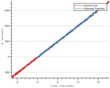
Fig. 10a demonstrates the estimated trajectory (blue) and against the ground truth (red) for the high frequency tracking experiments. The noise levels experienced by algorithm can be seen in insets (columns 2-4). It can be seen that as the algorithm tracks the jitter, it also tracks the underlying signal. To better view the tracking performance, we show separate plots for tracking along the x- and y- direction against the tracking time in Fig. 2b with zoomed version for a short time in the right column. Thanks to the event sensor’s high sampling rate, we can accurately track the jitter both in the x- and y- directions while tracking the overall signal with perturbations greater than 10 arcseconds frequently seen in the plots at each timestamp. These plots demonstrate the efficacy the event sensor in tackling high frequency, high magnitude jitter. A high frequency actuation mechanism can be used to compensate for the computed motion at provides stabilisation.
5.4.2 Open Loop Tracking Accuracy
We focus on the comparatively low frequency (10Hz) case used for stable pointing. Stabilisation via the micromotion stage needs depends on accurately estimating of the sensor’s position. This raw position estimate is smoothed via the Kalman filter to provide a consistent and reliable estimate of the sensor’s position for the stabilisation task. Experiments in this section track stars in the event stream at Hz by accumulating event data for ms to generate event frames.
To quantify the open loop tracking accuracy, the estimated trajectory is aligned against the ground truth and the Root Mean Squared Error (RMSE) metric is reported for various noise levels .
| (7) |
where is the computed position against the ground truth position at time with a noise level . The computed metric provides an estimate of the average pointing discrepancy in the system at a particular noise level. Tracking accuracy for the linear, square and circle trajectories for degrees is reported in the Fig. 2. Three inset marked in the first column provide details of the estimated position for a short time period in the other three columns. Additionally, results for various trajectories is summarised in Fig. 11 which reports the RMSE tracking error across various noise levels for the linear, circle and square trajectories as well the high frequency tracking task described in Sec. 5.4.1.


10 arcsec line represents the precision that the system is aiming for. It can be seen that the tracking error remains below the 10 arcsec cut-off for noise levels up to degrees. Tracking accuracy degrades with increased noise. As expected, high frequency noise is more difficult to instantaneously estimate. On-board a typical small satellite, the noise is low frequency and falls within the operational range of the tracker (below degrees). Results show that the system can reliably estimate the motion of the sensor within the required 10-arcsec level of accuracy. Tracking high-frequency perturbations leads to greater errors compared to the tracking the smoothed signal via the Kalman filter for the linear trajectory.
5.5 Closed Loop Stabilisation accuracy
Having a good grasp of the tracking capabilities of the proposed system, we demonstrate its effectiveness in providing ultra-fine pointing stabilisation. This requires the translation of positional estimation into stabilisation command for the piezoelectric stage.
To quantify the stabilisation performance of the system, we report the spread of the deviation from the required pointing direction over time. The smaller the spread of the points across the mean, the better the pointing position is maintained over time. We report this spread, effectively the contours of the estimated Gaussian fit to the deviation from the required pointing position, for various trajectories in Fig. 2. As before, we aim for most of the stabilised positions to fall within 10 arcseconds radius of the required pointing direction on the event sensor, as indicated by the yellow circle in the Fig. 2(left). On the right, the evolution of stabilisation across time is shown. When stabilisation is requested, the system is driven to the required position by the PID controller over time. This leads to a reduction in the pointing error seen at the beginning. The system then actively computes and corrects for any deviations from the pointing direction. This stabilised trajectory with some perturbations can be seen in the plots. High magnitude deviations, such as those seen in the square trajectory, when sudden changes in position occur at the corners, leads to deviation in the pointing direction which are subsequently corrected, and stable pointing is maintained. It should be noted the under the simulated noise the performance remains well below 10 arcseconds in Table 3.
| noise level (degrees) | ||||
|---|---|---|---|---|
| trajectory | ||||
| linear | 3.36 | 2.61 | 3.62 | |
| 2.61 | 2.73 | 3.70 | ||
| square | 3.28 | 3.87 | 4.59 | |
| 3.74 | 4.29 | 5.22 | ||
| circle | 7.79 | 3.74 | 4.71 | |
| 4.21 | 4.63 | 5.01 | ||
5.6 Computational Time
We run a benchmarking sequence 35 seconds long to benchmark the time taken by various component of the pipeline on different machines for the open loop star tracking task. The same code in run on two different machines: desktop representing a modern desktop machine equipped with an Intel Core i7-8700 CPU and Nvidia Titan X GPU and Jetson which is the Jetson Nano 2 with an onboard GPU. The code utilises GPUs for noise suppression (referred to as Median filtering in the Tab. 4), while the rest of the code runs on the CPU. The desktop represents a reference value which can be treated as the upper bound for the satellite case.
Table 4 show that our proposal can run at nearly 50Hz, signifying the highest update rate at which the piezoelectric stage can be driven on-board. This update rate is faster than what would be available using a conventional sensing modality such as a CMOS/CCD sensor.
| Machine | System time (Frequency) | Star Detection Time (%) | Median Filtering Time (GPU) (%) |
|---|---|---|---|
| desktop | 3.26 ms (306Hz) | 1.21 ms (37.11%) | 1.77 ms (54.29%) |
| Jetson | 20.39 ms (49Hz) | 4.39 ms (21.53%) | 14.58 ms (71.50%) |


6 Conclusion
As the requirement for accurate pointing increases on board commercial missions, new sensing modalities need to be incorporated into payloads to enable high frequency high accuracy pointing. In this work, we have presented a novel payload using a combination of a event sensor and piezoelectric motion stage to achieve ultra-fine attitude estimation and ultra-fine pointing stabilisation. In contrast to the ADCS which achieves pointing stabilisation by manoeuvring the whole satellite body, our proposal offers additional pointing corrections by separately controlling the imaging sensor, alleviating the residual pointing errors in the ADCS. We have demonstrated the feasibility of COTS hardware and developed algorithms that can run efficiently onboard at a much higher frequency than commercially available star tracking based pointing mechanism. With detailed experiments, we have reported results for the open loop star tracking as well as the closed loop stabilisation tasks. We have shown that the system achieves attitude estimation and stabilisation that can complement existing ADCS solutions.
7 Acknowledgements
This work has been supported by the SmartSat CRC, whose activities are funded by the Australian Government’s CRC Program. Tat-Jun Chin is the SmartSat CRC Professorial Chair of Sentient Satellites.
References
- [1] Saeed Afshar, Andrew Peter Nicholson, Andre Van Schaik, and Gregory Cohen. Event-based object detection and tracking for space situational awareness. IEEE Sensors Journal, 20(24):15117–15132, 2020.
- [2] Stuart Bennett. Development of the pid controller. IEEE Control Systems Magazine, 13(6):58–62, 1993.
- [3] Cesar Cadena, Luca Carlone, Henry Carrillo, Yasir Latif, Davide Scaramuzza, José Neira, Ian Reid, and John J Leonard. Past, present, and future of simultaneous localization and mapping: Toward the robust-perception age. IEEE Transactions on robotics, 32(6):1309–1332, 2016.
- [4] Gregory Cohen, Saeed Afshar, Brittany Morreale, Travis Bessell, Andrew Wabnitz, Mark Rutten, and André van Schaik. Event-based sensing for space situational awareness. The Journal of the Astronautical Sciences, 66:125–141, 2019.
- [5] Martin A Fischler and Robert C Bolles. Random sample consensus: a paradigm for model fitting with applications to image analysis and automated cartography. Communications of the ACM, 24(6):381–395, 1981.
- [6] Guillermo Gallego, Tobi Delbrück, Garrick Orchard, Chiara Bartolozzi, Brian Taba, Andrea Censi, Stefan Leutenegger, Andrew J Davison, Jörg Conradt, Kostas Daniilidis, et al. Event-based vision: A survey. IEEE transactions on pattern analysis and machine intelligence, 44(1):154–180, 2020.
- [7] Erik Høg. Tycho star catalogs: The 2.5 million brightest stars. In Encyclopedia of Astronomy & Astrophysics, pages 1–3. CRC Press, 2001.
- [8] Mohsi Jawaid, Ethan Elms, Yasir Latif, and Tat-Jun Chin. Towards bridging the space domain gap for satellite pose estimation using event sensing. In 2023 IEEE International Conference on Robotics and Automation (ICRA), pages 11866–11873. IEEE, 2023.
- [9] Richard J Meinhold and Nozer D Singpurwalla. Understanding the Kalman filter. The American Statistician, 37(2):123–127, 1983.
- [10] Yonhon Ng, Yasir Latif, Tat-Jun Chin, and Robert Mahony. Asynchronous kalman filter for event-based star tracking. In Computer Vision – ECCV 2022 Workshops: Tel Aviv, Israel, October 23–27, 2022, Proceedings, Part I, page 66–79, Berlin, Heidelberg, 2023. Springer-Verlag.
- [11] Gabor Papotti. A Star Tracker based Attitude Determination System. PhD thesis, ResearchSpace@ Auckland, 2021.
- [12] Christopher Pong. On-orbit performance & operation of the attitude & pointing control subsystems on ASTERIA. Proceedings of the Small Satellite Conference, 2018.
- [13] Christopher M Pong, Sungyung Lim, Matthew W Smith, David W Miller, Jesus S Villaseñor, and Sara Seager. Achieving high-precision pointing on exoplanetsat: initial feasibility analysis. In Space Telescopes and Instrumentation 2010: Optical, Infrared, and Millimeter Wave, volume 7731, pages 620–635. SPIE, 2010.