Three-level Spaser System: a Semi-Classical Analysis
Abstract
We theoretically study a nanospaser system, which consists of a spherical silver nanoparticle embedded inside a sphere composed of dye molecules. The gain of the system, dye molecules, is described by a three-level model, where the transition frequency between the lowest two energy levels is close to the surface plasmon frequency of the nanosphere. Contrary to a two-level model of spaser, the three-level model takes into account finite relaxation time between the high energy levels of the gain medium. These relaxation processes affect both the spaser threshold and the number of generated plasmons in the continuous wave regime. While for a two-level model of a spaser the number of generated plasmons has a linear dependence on the gain, for the three-level model this dependence becomes quadratic.
I Introduction
Scaling down electronic and optical systems to harness their optimum efficiency has been a goal of today’s scientific and industrial research. Among the research fields, working in this direction, nanoplasmonics plays an important role due to its unique possibilities and broad applications [1, 2, 3]. In nanoplasmonics, the light is confined within a sub-wavelength scale, which results in a strong enhancement of the optical field. Some of the notable application of nanoplasmonics are in the areas of near-field optics [4, 5], bio-sensing [6, 7, 8], surface plasmon-based photo-detectors [9, 10], spaser[11, 12, 13] and many others. Spaser (surface plasmon amplification by stimulated emission of radiation), which has experienced a vast development over the last decade, plays a special role in this list. It was introduced in the early 2000’s [14] by David. J. Bergman and Mark. I . Stockman [15, 16], and throughout the time has paved its way up as a miniature source of spectrally tunable stimulated emission [17, 18]. Apart from the mainstream research, spaser has found numerous applications in different areas such as opto-electronic systems[19, 20, 21, 22, 23, 24, 25], sensing in biological and chemical agents[26, 27, 28] and also as a biological probe[29, 30] in disease therapeutics and diagnostics.
The whole idea of spaser is based on the existence of localized surface plasmons, which are characterized by a high concentration of optical energy within a nanoscale range[31]. Such strong concentration of optical field combined with stimulated emission [14] process allow to design a nanoscale laser - spaser. Different variations of such nanoscopic lasers were proposed theoretically and realized experimentally. The first of the type[32] was introduced in 2008 and was based on an array of plasmonic resonators. A year later, a spaser, based on Localized Surface Plasmons Resonance[33, 34](LSPR), was demonstrated experimentally[35], which contained a gold sphere embedded inside a dye. The same design has been also been studied for a cancer diagnosis and treatment by Ganzala et al[29] in 2017
The design of spaser based on a gain nanorod placed near plasmonic metal with the dimensions in micrometers has been considered in Ref. [36, 37]. Recently, the topological spasers of type I and II were introduced[38, 39, 40], where the spaser dynamics is protected by nontrivial topological properties of either a plasmonic system[38] or a gain medium[39, 40].
Spaser can be understood as a nanoplasmonic counterpart of a normal laser[41]. It consists of two major components: a metal resonator and a gain medium. Usually, the metal is silver due to its low non-radiative losses, however, gold or aluminum can also be used for the spaser operating at high frequency. The gain medium is usually dye molecules, with the gap close to the SP frequency. Apart from dyes, materials[42, 43, 44] with non-linear effects that exhibit topological resonance, have also been studied as a suitable gain. Additionally, the system may also be placed in an appropriate dielectric environment, which can be used to adjust the SP frequency of a nanosphere.
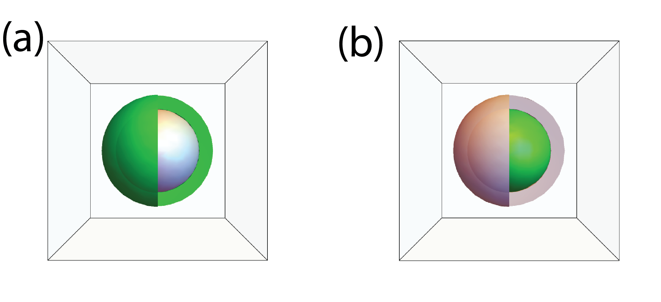
The two basic possibilities of how a gain medium can be introduced into a spaser system are shown in Fig. 1: i) gain encapsulating the solid nanosphere ii) gain placed inside a metal nanoshell. Below, we consider only the first case when the gain is placed outside the solid silver metal nanosphere as shown in Fig. 1a. Additionally, this system is placed in water which will further help to adjust the LSP frequency().
Theoretical modeling[18] of such nanolaser[35] is mostly in agreement with the experimental results, apart from the behavior of the spaser at a large value of electric pumping. In the present paper, we are using the same theoretical model[18] of spaser with some modifications, which can address the unexplained behavior. Namely, we consider a three-level model for the gain while in Ref. [18] only two levels were introduced for the gain medium.
II Model and Main Equations
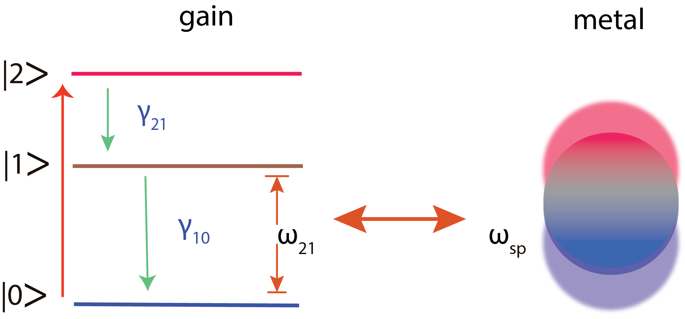
We consider a gain medium consisting of three energy levels with the corresponding populations , and . This approach is similar to the previously studied 2-level [18] system, but with an additional energy level added to account for the finite relaxation rate of electron population from the highest level to the second excited level. Many other noticeable works have been done previously to deal with the effects of multi-level[45, 46] on the spasing process. However, this paper describes an elegant way to account for coherent processes in gain, which makes our findings in close appropriation with the experimental ones as discussed below. The general schematics of transition within the system is shown in Fig. 2.
The gain system is pumped by an external light, which excites the system from the ground state to the second excited state with the transition (gain) rate . The excited states of the system are also characterized by relaxation rates and , which represent the transitions and respectively. The gain medium is coupled to the plasmonic system through the field-dipole interaction and it is at the almost resonant condition with the frequency is close to the surface plasmon frequency, , see Fig. 2.
For more than two mediums present in the system, we use the standard Laplace equation approach as adopted in a popular spaser research[29] to calculate the field of the Localized Surface Plasmons. In the spherical system, we consider the electric potential of the dipole mode to be of the form
| (1) |
where labels the medium (), and are coefficients corresponding to medium , and is a spherical harmonics and . The Maxwell’s continuity equations across the interfaces of the layers are given by the following expressions
| (2) | ||||
| (3) |
where is the permittivity of medium . For our system, which consists of 3 layers, silver sphere, dye, and water, we solve Eqs. (2) and (3) to obtain permittivity of silver () as a function of permittivities of dye () and water (), i.e.,
| (4) |
The frequency of LSPs is then obtained by equating to the experimental value [47]
| (5) |
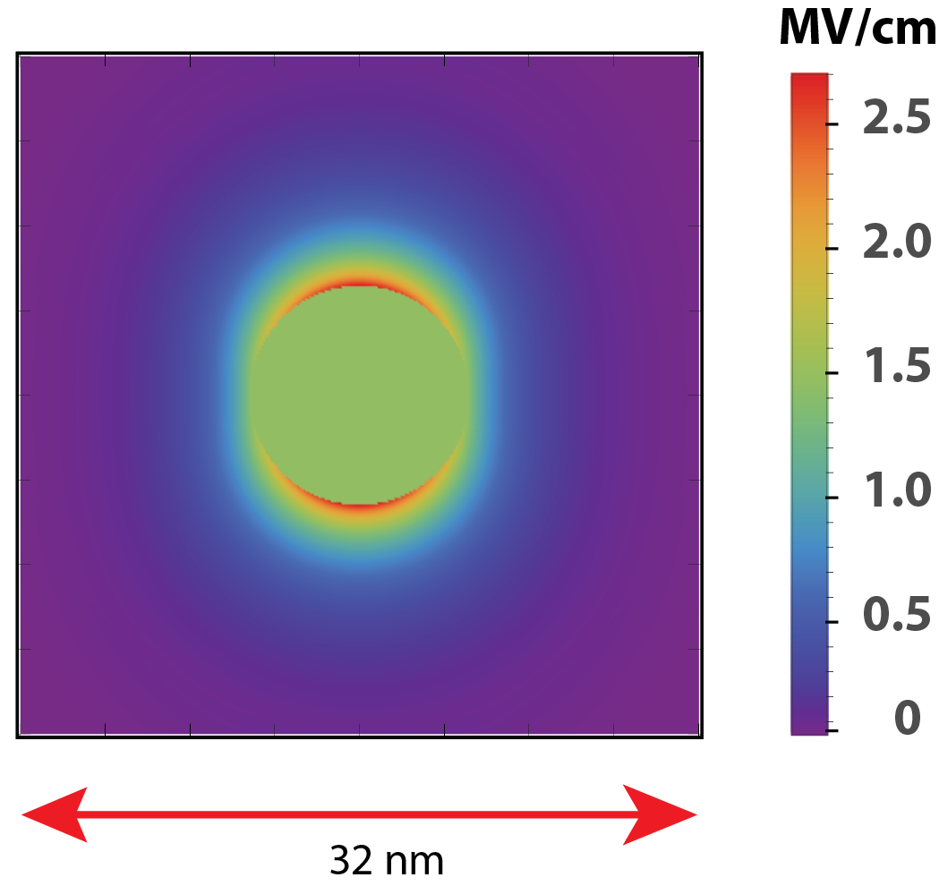
The plasmon dipole mode creates a highly localized dipole-field as shown in the cross-section diagram in Fig. 3. The corresponding operator of electric field[14, 18] can be expressed in terms of creation and annihilation operators, and , of SP,
| (6) |
where
| (7) |
Here, the geometrical parameter is given by the following expression
| (8) |
The Hamiltonian of a spaser can be expressed in terms of individual Hamiltonians of surface plasmons and the gain medium, and the dipole type interaction Hamiltonian of the SP and the gain:
| (9) |
Here is the total volume of the gain medium and is the transition dipole moment operator of the gain medium.
In this article, we adopt a quasi-classical approach [18, 2] to study the properties of SPs, where the operators and are treated as classical variables represented in the form of a time dependent variable with being the slow varying amplitude. Then, the number of SPs in a given mode then can be written as .
Below we assume that the corresponding dipole matrix elements are nonzero only between the levels and of the gain system, i.e., only the transitions between these levels can generate SPs. These interactions can be also characterized by the Rabi frequency[48], which is given by the following expression
| (10) |
where .
We describe the gain system within the density matrix approach with the corresponding equation of motion
| (11) |
where is the density matrix of three level gain system. Using Rotating Wave Approximation(RWA), we can express as slow-varying diagonal terms and fast varying non-diagonal terms with frequency .
| (15) |
It is convenient to introduce the following notations: , and . Then equations for the elements of the density matrix, which can be derived from Eq. (11), take the following form
| (16) | |||
| (17) | |||
| (18) | |||
| (19) |
where is the transition frequency between and levels of the gain medium and is the rate of excitation from the level to the level by an external pulse. In the above equations, we also introduced the relaxation rates: polarization relaxation rate and the spontaneous relaxation rates and between the corresponding states as indicated by the indices.
The equation of motion for SPs is obtained from Hamiltonian (9) and is given by the following expression
| (20) |
where the plasmon relaxation rate is introduced, . Since the transitions between the levels and are due to coupling to the SPs, the corresponding relaxation rate, , can be expressed as
| (21) |
Equations (16)-(20) determine the dynamics of three level spaser. First, we analyze the stationary solution of these equations, i.e., the continuous wave regime of a spaser. In this regime, the time derivatives in the left hand sides of Eqs. (16)-(20) are zero. It is convenient to introduce the population inversions through the following expressions
| (22) | |||
| (23) |
Then taking into account that , we can express populations of different levels in terms of as follows
| (24) | ||||
| (25) | ||||
| (26) |
Substituting Eqs. (24)-(26) into the system of equations (16)-(20) we obtain the following solution of the stationary equations
| (27) |
| (28) |
| (29) |
In the above equations we assumed that the Rabi frequency is constant within the gain medium and the corresponding integrals in Eqs. (18) and (19) can be replaced by . Here the spasing frequency is given by the following expression
| (30) |
where , and in the absence of detuning, i.e., if , it is equal to .
From the above expressions we can identify the effect of relaxation rate on the main spaser characteristics such as population inversion , spasing frequency , threshold, and the number of generated plasmons . From Eqs. (28), (30) one can see that both the population inversion and the spasing frequency do not depend on .
The spasing threshold can be found from Eq. (29), where the threshold is determined from the condition ,
| (31) |
Thus the spaser threshold depends on the relaxation rate, , but since this dependence is weak. Taking into account that , we can find the correction to the threshold determined by the two-level spaser model
| (32) |
where .
Finite relaxation rate also affects the number of generated plasmons, see Eq. (29). When is large enough, i.e., , we can consider as a small parameter and find expansion of Eq. (29) in the powers of as follows
| (33) |
The first term in this expansion is the result for the two-level spaser system[18], for which . In this case, the number of generated SPs is proportional to the gain, . The second and the third terms give the correction due to finite relaxation rate, . These terms introduce quadratic dependence on .
III Results and Discussions
III.1 System and Parameters
The spaser system is shown schematically in Fig. 1(a). A solid silver sphere of radius nm is enclosed with a spherical dye layer making the total radius of the system 16 nm. The dielectric permittivity of the dye is , water is and that of the metal was obtained from the experimental data [47] of optical constants. The gain medium has an electronic band-gap of eV. We have also used a small detuning ( eV) to highlight the robustness of the spaser under small frequency mismatch. The selection of these specific dimensions of the system ensures the matching of SPs frequency to the transition frequency . Also, Additional parameters that is used are: eV, esu and the density of chromophores in a gain medium cm-3.
III.2 Spasing in Continuous Wave (CW) Regime
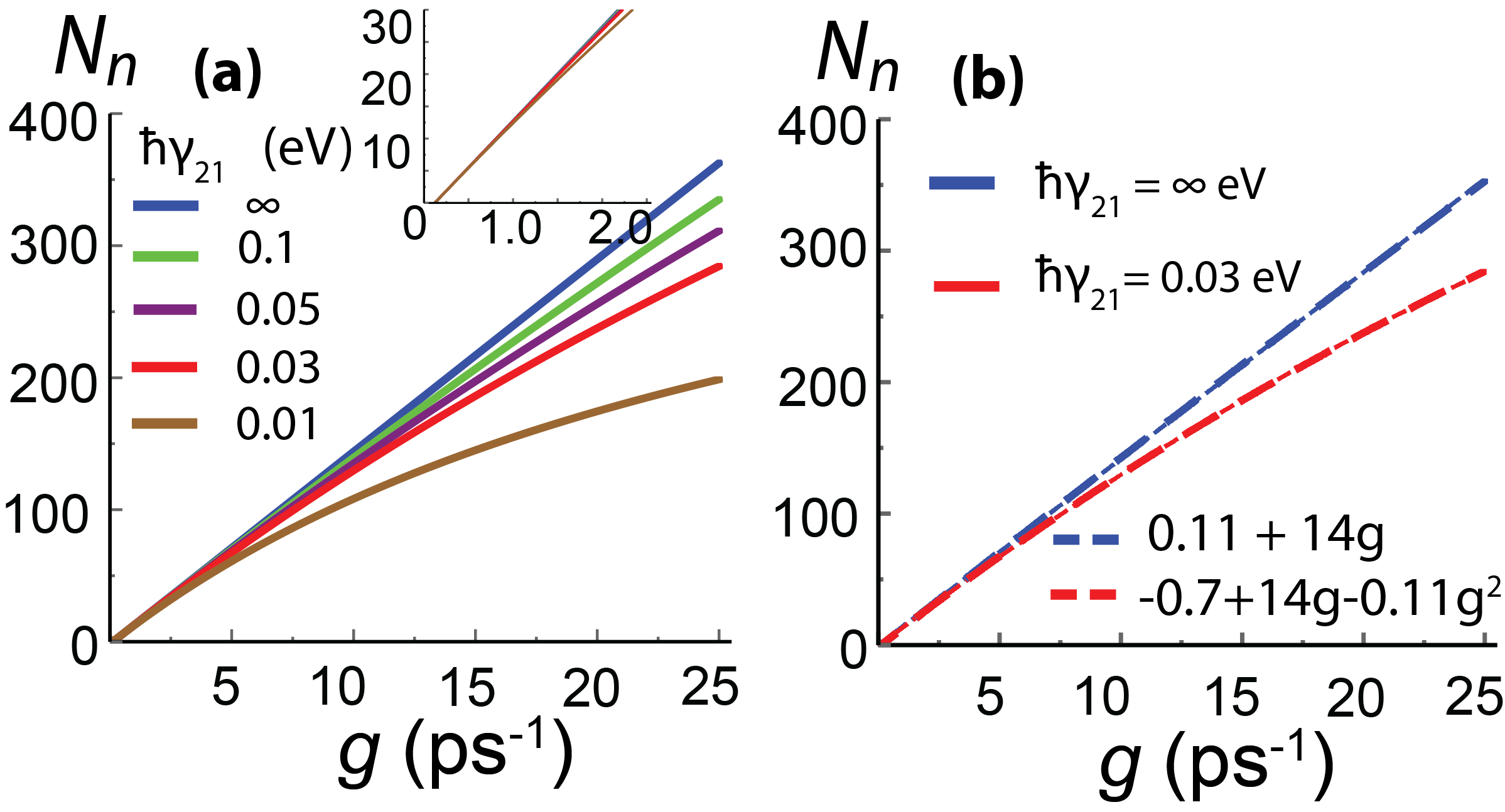
In this subsection, we study the stationary solution, which is given by Eq. (29), as a function of the pumping rate, : . The external optical pulse excites the gain system from the ground level, , to the second excited level, . If the relaxation from the level to first excited level is fast enough, then the spaser system is equivalent to the two-level system[18]. In this case, we observe the linear dependence of on the gain rate , see Fig. 4(a), where the fast relaxation rate, , is shown by the blue line.
With decreasing the relaxation rate, , the first excited state, , becomes less populated at a given value of the pump rate, , which results in a smaller number of the generated SP. The corresponding dependencies, , are shown in Fig. 4(a) for in the range of 0.01 eV and 0.1 eV, i.e., for the relaxation time in the range of 6.5 fs and 65 fs. The data clearly show that monotonically decreases with . For example, at ps-1, the number of plasmons decreases by almost a factor of 2 when the relaxation rate decrease from a large value to 0.01 eV. The dependence of on becomes also parabolic at finite values of .
To provide a more clear comparison of the two-level and the three-level spaser systems, we show in Fig. 4(b) the results for (two-level system) and eV, i.e, the corresponding relaxation time is 22 fs, and interpolate them with parabolic dependence. While for the two-level system we have a clear linear dependence on , the three-level system has an extra quadratic term. Interestingly, these calculations match the previous experimental findings [29, 45], where the does not show a linear dependence on the pumping rate, but rather follows a parabolic dependence at a higher pumping rate .
III.3 Spasing in a Dynamic Regime
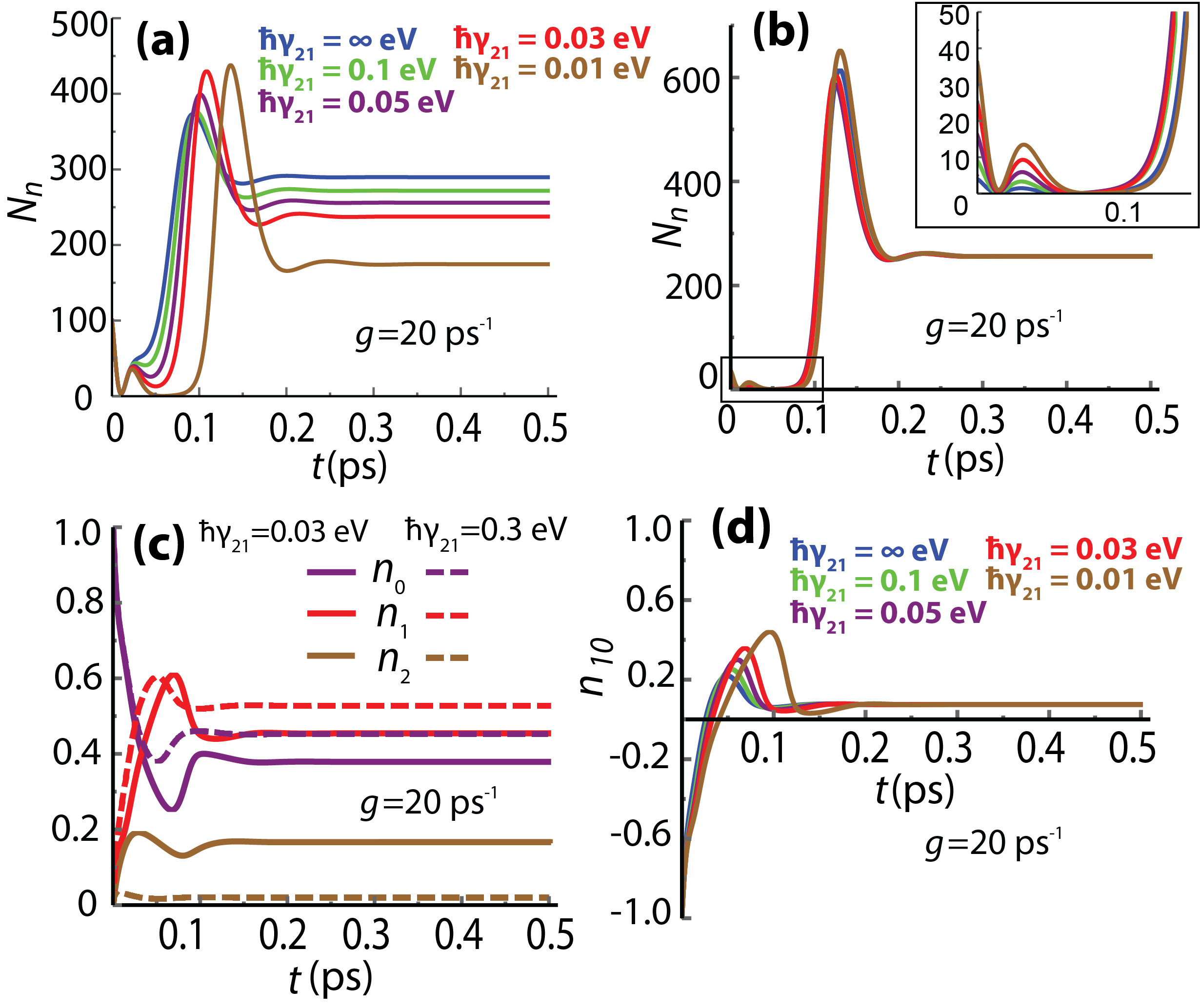
The time dynamics of three-level spaser is shown in Fig. 5(a) for different values of . The initial number of SP, , does not affect the final value of . Thus, we arbitrarily set the initial value of equals 100. The temporal profile of is similar for different values of with one difference that with decreasing more pronounced oscillation at ps are developed. The final stationary values of follows the results shown in Fig. 4.
To illustrate that the stationary value of does not depend on the initial condition, we show in Fig. 5(b) the profile for different initial values. The relaxation rate is eV. The results show that the initial value of only affects the amplitude of oscillations while the stationary solution is independent of .
Other characteristics of the spaser dynamics are populations of three levels of the gain medium, , , and . They are shown in Fig. 5(c) for fast and slow relaxation rates, where the solid lines correspond to eV while the dashed lines correspond to eV. The data show that with a fast relaxation rate ( eV) the population of the high energy level is almost zero, which corresponds to the limit of a two-level spaser system. Also, as expected, with increasing the relaxation rate, the populations of the ground and the first excited states, and , increases while the population of the second excited state, , decreases. The population inversion, which is the difference between populations and , , is the same for both large and small relaxation rates. To illustrate this property we show in Fig. 5(d) the population inversion for different values of relaxation rate . The values of are the same as in Fig. 5(a). In all cases, the stationary population inversion does not depend on the relaxation rate, . This is consistent with expression (28), the right-hand side of which does not depend on .
IV Conclusion
Spaser is a unique system where the coupling of the plasmonic system and the gain medium results in the coherent generation of the localized plasmons at the nanoscale. The theories of spaser that are based on the two-level system of gain have their limitation in explaining the spasing behavior at the high pumping rates. In the present paper, we considered, within a semi-classical approach, a three-level gain system to identify the effects of relaxation between the non-spasing levels on the spaser dynamics. Our results show that the number of generated surface plasmons strongly depends on the relaxation rate . At large values of , i.e., fast relaxation, the three-level system converges to the regular two-level spaser system[18] with linear dependence of the number of generated plasmons on the pumping rate. However, at smaller values of , the dependence of the number of plasmons on the pumping rate becomes parabolic, which is more pronounced at large pump intensity. Such behavior is consistent with experimental results[29, 45]. Our spaser model can be beneficial in improving the efficacy of existing models and comparison with experimental results.
V Acknowledgments
Major funding was provided by Grant No. DE-FG02-01ER15213 from the Chemical Sciences, Biosciences and Geosciences Division, Office of Basic Energy Sciences, Office of Science, US Department of Energy. Numerical simulations were performed using support by Grant No. DE-SC0007043 from the Materials Sciences and Engineering Division of the Office of the Basic Energy Sciences, Office of Science, US Department of Energy.
References
- [1] M. I. Stockman, “Nanoplasmonics: The physics behind the applications,” Phys. Today, vol. 64, no. 2, pp. 39–44, 2011.
- [2] M. I. Stockman, “Nanoplasmonics: past, present, and glimpse into future,” Optics express, vol. 19, no. 22, pp. 22029–22106, 2011.
- [3] B. Dong, Y. Ma, Z. Ren, and C. Lee, “Recent progress in nanoplasmonics-based integrated optical micro/nano-systems,” Journal of Physics D: Applied Physics, vol. 53, no. 21, p. 213001, 2020.
- [4] S. Kawata, Y. Inouye, and P. Verma, “Plasmonics for near-field nano-imaging and superlensing,” Nature Photonics, vol. 3, no. 7, pp. 388–394, 2009.
- [5] N. Kholmicheva, L. R. Romero, J. Cassidy, and M. Zamkov, “Prospects and applications of plasmon-exciton interactions in the near-field regime,” Nanophotonics, vol. 8, no. 4, pp. 613–628, 2018.
- [6] J. N. Anker, W. P. Hall, O. Lyandres, N. C. Shah, J. Zhao, and R. P. Van Duyne, “Biosensing with plasmonic nanosensors,” Nanoscience and Technology: A Collection of Reviews from Nature Journals, pp. 308–319, 2010.
- [7] H. Kim, J. U. Lee, S. Kim, S. Song, and S. J. Sim, “A nanoplasmonic biosensor for ultrasensitive detection of alzheimer’s disease biomarker using a chaotropic agent,” ACS sensors, vol. 4, no. 3, pp. 595–602, 2019.
- [8] D. Zhang, Q. Zhang, Y. Lu, Y. Yao, S. Li, and Q. Liu, Nanoplasmonic biosensor using localized surface plasmon resonance spectroscopy for biochemical detection. Springer, 2017.
- [9] Y. Liu, J. Guo, J. Jiang, W. Chen, L. Zhao, W. Chen, R. Liang, and J. Xu, Simple Preparations for Plasmon-Enhanced Photodetectors. IntechOpen, 2019.
- [10] L. Tang, S. E. Kocabas, S. Latif, A. K. Okyay, D.-S. Ly-Gagnon, K. C. Saraswat, and D. A. Miller, “Nanometre-scale germanium photodetector enhanced by a near-infrared dipole antenna,” Nature Photonics, vol. 2, no. 4, pp. 226–229, 2008.
- [11] M. I. Stockman, “Brief history of spaser from conception to the future,” Advanced Photonics, vol. 2, no. 5, p. 054002, 2020.
- [12] S. I. Azzam, A. V. Kildishev, R.-M. Ma, C.-Z. Ning, R. Oulton, V. M. Shalaev, M. I. Stockman, J.-L. Xu, and X. Zhang, “Ten years of spasers and plasmonic nanolasers,” Nature, vol. 9, no. 1, pp. 1–21, 2020.
- [13] M. Premaratne and M. I. Stockman, “Theory and technology of spasers,” Advances in Optics and Photonics, vol. 9, no. 1, pp. 79–128, 2017.
- [14] D. J. Bergman and M. I. Stockman, “Surface plasmon amplification by stimulated emission of radiation: quantum generation of coherent surface plasmons in nanosystems,” Physical review letters, vol. 90, no. 2, p. 027402, 2003.
- [15] J. Aizpurua, H. A. Atwater, J. J. Baumberg, S. I. Bozhevolnyi, M. L. Brongersma, J. A. Dionne, H. Giessen, N. Halas, Y. Kivshar, M. F. Kling, F. Krausz, S. Maier, S. V. Makarov, M. Mikkelsen, M. Moskovits, P. Norlander, T. Odom, A. Polman, C. W. Qiu, M. Segev, V. M. Shalaev, P. Törmä, D. P. Tsai, E. Verhagen, A. Zayats, X. Zhang, and N. I. Zheludev, “Mark stockman: Evangelist for plasmonics,” ACS Photonics, vol. 8, no. 3, pp. 683–698, 2021.
- [16] A. Boltasseva, V. M. Shalaev, and N. I. Zheludev, “Mark stockman, the knight of plasmonics,” Nature Photonics, vol. 15, no. 5, pp. 321–322, 2021.
- [17] K. Li, X. Li, M. I. Stockman, and D. J. Bergman, “Surface plasmon amplification by stimulated emission in nanolenses,” Physical review B, vol. 71, no. 11, p. 115409, 2005.
- [18] M. I. Stockman, “The spaser as a nanoscale quantum generator and ultrafast amplifier,” Journal of Optics, vol. 12, no. 2, p. 024004, 2010.
- [19] I. S. Mark, “Spasers to speed up cmos processors,” Google Patents, 2018.
- [20] M. Khajavikhan, A. Simic, M. Katz, J. H. Lee, B. Slutsky, A. Mizrahi, V. Lomakin, and Y. J. N. Fainman, “Thresholdless nanoscale coaxial lasers,” vol. 482, no. 7384, pp. 204–207, 2012.
- [21] C.-Z. J. A. P. Ning, “Semiconductor nanolasers and the size-energy-efficiency challenge: a review,” vol. 1, no. 1, p. 014002, 2019.
- [22] J. Shane, Q. Gu, F. Vallini, B. Wingad, J. S. T. Smalley, N. C. Frateschi, and Y. Fainman, “Thermal considerations in electrically-pumped metallo-dielectric nanolasers,” vol. 8980, p. 898027, 2014.
- [23] K. Shen, C. Ku, C. Hsieh, H. Kuo, Y. Cheng, and D. P. J. A. M. Tsai, “Deep‐ultraviolet hyperbolic metacavity laser,” vol. 30, no. 21, p. 1706918, 2018.
- [24] K. Ding, J. O. Diaz, D. Bimberg, C.-Z. J. L. Ning, and P. Reviews, “Modulation bandwidth and energy efficiency of metallic cavity semiconductor nanolasers with inclusion of noise effects,” vol. 9, no. 5, pp. 488–497, 2015.
- [25] V. Dolores-Calzadilla, B. Romeira, F. Pagliano, S. Birindelli, A. Higuera-Rodriguez, P. J. Van Veldhoven, M. K. Smit, A. Fiore, and Heiss, “Waveguide-coupled nanopillar metal-cavity light-emitting diodes on silicon,” Nature Communications, vol. 8, no. 1, pp. 1–8, 2017.
- [26] P.-J. Cheng, Z.-T. Huang, J.-H. Li, B.-T. Chou, Y.-H. Chou, W.-C. Lo, K.-P. Chen, T.-C. Lu, and T.-R. Lin, “High-performance plasmonic nanolasers with a nanotrench defect cavity for sensing applications,” ACS Photonics, vol. 5, no. 7, pp. 2638–2644, 2018.
- [27] S. Wang, B. Li, X.-Y. Wang, H.-Z. Chen, Y.-L. Wang, X.-W. Zhang, L. Dai, and R.-M. Ma, “High-yield plasmonic nanolasers with superior stability for sensing in aqueous solution,” ACS Photonics, vol. 4, no. 6, pp. 1355–1360, 2017.
- [28] L. V. Wang and S. Hu, “Photoacoustic tomography: in vivo imaging from organelles to organs,” science, vol. 335, no. 6075, pp. 1458–1462, 2012.
- [29] E. I. Galanzha, R. Weingold, D. A. Nedosekin, M. Sarimollaoglu, J. Nolan, W. Harrington, A. S. Kuchyanov, R. G. Parkhomenko, F. Watanabe, and Z. Nima, “Spaser as a biological probe,” Nature communications, vol. 8, no. 1, pp. 1–7, 2017.
- [30] X. Fan and S.-H. Yun, “The potential of optofluidic biolasers,” Nature methods, vol. 11, no. 2, pp. 141–147, 2014.
- [31] D. J. Bergman and D. Stroud, “Physical properties of macroscopically inhomogeneous media,” Solid state physics, vol. 46, pp. 147–269, 1992.
- [32] N. I. Zheludev, S. Prosvirnin, N. Papasimakis, and V. Fedotov, “Lasing spaser,” Nature photonics, vol. 2, no. 6, pp. 351–354, 2008.
- [33] K. A. Willets and R. P. Van Duyne, “Localized surface plasmon resonance spectroscopy and sensing,” Annu. Rev. Phys. Chem., vol. 58, pp. 267–297, 2007.
- [34] K. M. Mayer and J. H. Hafner, “Localized surface plasmon resonance sensors,” Chemical reviews, vol. 111, no. 6, pp. 3828–3857, 2011.
- [35] M. Noginov, G. Zhu, A. Belgrave, R. Bakker, V. Shalaev, E. Narimanov, S. Stout, E. Herz, T. Suteewong, and U. Wiesner, “Demonstration of a spaser-based nanolaser,” Nature, vol. 460, no. 7259, pp. 1110–1112, 2009.
- [36] R. F. Oulton, V. J. Sorger, T. Zentgraf, R.-M. Ma, C. Gladden, L. Dai, G. Bartal, and X. Zhang, “Plasmon lasers at deep subwavelength scale,” Nature, vol. 461, no. 7264, pp. 629–632, 2009.
- [37] M. H. Motavas and A. Zarifkar, “Low threshold nanorod-based plasmonic nanolasers with optimized cavity length,” Optics and Laser Technology, vol. 111, pp. 315–322, 2019.
- [38] J.-S. Wu, V. Apalkov, and M. I. Stockman, “Topological spaser,” Physical review letters, vol. 124, no. 1, p. 017701, 2020.
- [39] R. Ghimire, J.-S. Wu, V. Apalkov, and M. I. Stockman, “Topological nanospaser,” Nanophotonics, vol. 9, no. 4, pp. 865–874, 2020.
- [40] R. Ghimire, F. Nematollahi, J.-S. Wu, V. Apalkov, and M. I. Stockman, “Tmdc-based topological nanospaser: single and double threshold behavior,” ACS Photonics, vol. 8, no. 3, pp. 907–915, 2021.
- [41] T. H. Maiman et al., “Stimulated optical radiation in ruby,” 1960.
- [42] G.-B. Liu, W.-Y. Shan, Y. Yao, W. Yao, and D. Xiao, “Three-band tight-binding model for monolayers of group-vib transition metal dichalcogenides,” Physical Review B, vol. 88, no. 8, p. 085433, 2013.
- [43] S. Withanage, T. Nanayakkara, U. Wijewardena, A. Kriisa, and R. Mani, “The role of surface morphology on nucleation density limitation during the cvd growth of graphene and the factors influencing graphene wrinkle formation,” Journal Name: MRS Advances; Journal Volume: 4; Journal Issue: 61-62, p. Medium: X; Size: 3337 to 3345, 2019.
- [44] F. Nematollahi, S. A. O. Motlagh, J.-S. Wu, R. Ghimire, V. Apalkov, and M. I. Stockman, “Topological resonance in weyl semimetals in a circularly polarized optical pulse,” Physical Review B, vol. 102, no. 12, p. 125413, 2020.
- [45] P. Song, J.-H. Wang, M. Zhang, F. Yang, H.-J. Lu, B. Kang, J.-J. Xu, and H.-Y. Chen, “Three-level spaser for next-generation luminescent nanoprobe,” Science advances, vol. 4, no. 8, p. eaat0292, 2018.
- [46] X.-L. Zhong and Z.-Y. Li, “All-analytical semiclassical theory of spaser performance in a plasmonic nanocavity,” Physical Review B, vol. 88, no. 8, p. 085101, 2013.
- [47] P. B. Johnson and R.-W. Christy, “Optical constants of the noble metals,” Physical review B, vol. 6, no. 12, p. 4370, 1972.
- [48] P. L. Knight and P. W. Milonni, “The rabi frequency in optical spectra,” Physics Reports, vol. 66, no. 2, pp. 21–107, 1980.