Theorem on the Compatibility of Spherical Kirigami Tessellations
Abstract
We present a theorem on the compatibility upon deployment of kirigami tessellations restricted on a spherical surface with patterned slits forming freeform quadrilateral meshes. We show that the spherical kirigami tessellations have either one or two compatible states, i.e., there are at most two isolated strain-free configurations along the deployment path. The theorem further reveals that the rigid-to-floppy transition from spherical to planar kirigami tessellations is possible if and only if the slits form parallelogram voids along with vanishing Gaussian curvature, which is also confirmed by an energy analysis and simulations. On the application side, we show a design of bistable spherical dome-like structure based on the theorem. Our study provides new insights into the rational design of morphable structures based on Euclidean and non-Euclidean geometries.
Introduction. Prescribed cuts on kirigami structures can induce desired deformations across various scales [1, 2, 3, 4, 5, 6, 7, 8]. This concept has been utilized to design metamaterials [9, 10, 11, 12, 13], morphable structures [14, 15, 16, 17, 18, 19], nanocomposites [20], soft robotics [21], and mechanical actuators [22]. In these applications, deployability and multistability play significant roles in determining the energy landscapes and morphing routes of the deploying process. The deformation of deployable (rigidly deployable, to be exact) kirigami structures can be idealized as continuous rotations of rigid panels connected by flexible hinges at the corner [18]. Thus, from the viewpoint of geometry, rigid deployability means having a series of piecewise isometric transformations between the undeployed configuration and any deployed configurations along the path of deployment. By contrast, multistability emerges if piecewise isometric transformations only exist at a finite number of states on the deployment path [9, 17], which is physically equivalent to discontinuous connections between stress-free configurations 111 Here we only consider stress-free stable configurations, which are determined solely by geometry.. Existence of such isometric transformations is also referred to as compatibility, a term originally proposed to design rigidly deployable origami tessellations [24, 25, 26].
In order to achieve desired energy landscapes with deployability or multistability upon deployment of kirigami structures, pioneering studies on geometrical and topological design principles have been carried out [27, 28, 29, 30, 31, 32, 17, 18, 33]. However, most existing works focus on classical patterns with planar symmetry [34], e.g., the well-known rotating squares [35] and kagome patterns [36], while freeform slit distributions can greatly expand the configuration space of kirigami structures [17, 18, 33]. Besides, nearly all the current works on morphable kirigami consider cutting flat sheets to engineer the deployed shapes in two or three dimensions, while very few are focused on cutting curved surfaces of non-Euclidean geometry. As an example of kirigami on curved developable surfaces, cylindrical shells with prescribed slits have been found to have unusual energy barriers with pop-up deformations compared to flat sheets [7]. Generically, kirigami perforated on non-developable surfaces (e.g., spherical surface) can benefit the design of shape-adaptive devices such as wearable sensors [37] and curvy imagers [38, 39]. But relevant research is still absent. Therefore, it is of great significance to develop general theories on the deployments and energy landscapes of kirigami structures covering freeform cutting patterns and Euclidean and non-Euclidean design spaces.
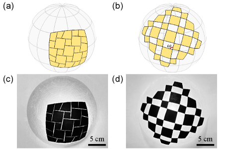
In this Letter, we focus on spherical quadrilateral kirigami (SQK) tessellations—the geodesic cuts divide curved sheets into columns and rows of arrayed quadrilateral panels [Fig. 1 (see Supplemental Material: Sec. IX [40] for fabrication details)] that are (ideally) connected by free rotational hinges at the corner 222We focus on patterns with a compact configuration. There are also kirigami patterns with no compact states, for which the cuts are voids of actual area, such as the lattice kirigami [27] and rhombi-slit kirigami [46].—and prove the following compatibility theorem:
Theorem 1
An SQK tessellation has either one or two compatible configurations.
First, we demonstrate the validity of this theorem for basic SQK tessellations [Fig. 2(a)] by investigating the corresponding compatibility condition 333In our discussion, the term tessellation stands for kirigami patterns with and ; we refer to patterns with or as kirigami strip, which are always rigidly deployable (see Fig. S1 and Supplemental Material: Sec. I [40]).. Each solution of the compatibility condition stands for a unique compatible configuration. We will verify that the number of such solutions is either one or two, depending on the geometry of the given kirigami pattern. Then, the proof is accomplished by the fact that the compatibility of an tessellation requires any of its parts to be compatible. Further, we give a corollary for implementing a spherical tessellation which guarantees two compatible configurations, and another one for a floppy planar tessellation with infinite compatible states. Finally, we design a reconfigurable kirigami structure with a dome-like deployed compatible configuration.
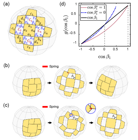
Compatibility theorem. We start by investigating SQK tessellations built on a sphere with Gaussian curvature . Based on spherical trigonometry [43], we restrict the slits to be minor arcs of great circles, and employ notations in Fig. 2(a) to formulate the compatibility condition. One can observe that, first, there are four connected quadrilateral slits surrounding the inner panel, with side lengths , , , , and opening angles , , , for . Second, since the slits are geodesic lines at the undeployed state, the side lengths satisfy . Given the side lengths of a slit , the opening angles , , and are uniquely determined as functions of (see Supplemental Material: Sec. II [40]). As a result, the shape of a slit relies on its neighbor by the conserved relations , for ( is defined as , and the same cyclic relationship follows below for other quantities). That is, the opening angles in adjacent slits (say, and ) are in a one-to-one correspondence, which we denote by . The explicit expressions of are provided in Supplemental Material: Sec. II [40]. Then we define the loop function for . From the expressions of , we observe that is smooth on the feasible domain for . The upper bound represents the stage where at least one of opening angles and reaches upon deployment, and the lower bound corresponds to the undeployed state. A valid compatible configuration requires that the value of is preserved around a loop of operations by , so that the compatibility condition reads
| (1) |
Each root of Eq. (1) represents one compatible state of a SQK tessellation. A trivial solution is at the undeployed state. To explore other compatible configurations, we will next show that is a strict convex function on . The first derivative of with respect to is given by , in which can be explicitly expressed as (see Supplemental Material: Sec. II [40])
| (2) |
where we have , and , , are functions of under given side lengths , , , and . Checking the right-hand side of Eq. (2), we find on . Also, we can prove under the condition (see Supplemental Material: Sec. III [40]). It then follows that on . Adding the smoothness of , we conclude that is a strict convex function on . As a result, Eq. (1) has at most two roots, and equivalently, a SQK tessellation has at most two compatible configurations. It further follows that an tessellation has at most two compatible states as well, because the number of its compatible configurations cannot exceed that of any of its parts. Therefore, Theorem 1 is proved.
Examples and verification. Theorem 1 asserts that an SQK tessellation can only have up to one compatible configuration away from its undeployed state. Here we demonstrate a special class of SQK tessellations that are assured to have the deployed compatible configuration. Assuming and for , the explicit expressions of the loop function—denoted by in this case—can be derived as (see Supplemental Material: Sec. III [40])
| (3) |
in which . Then, we solve Eq. (1) and obtain , indicating two compact compatible configurations [as shown in Fig. 2(b)]. Conversely, if a SQK tessellation is compatible at two compact states, we can conclude and , following the two conditions at and at . In general, for an SQK tessellation, we can investigate all of its parts and obtain:
Corollary 1
An SQK tessellation is compatible at two compact configurations if and only if the opposite side lengths are equal for each slit.
This corollary is instructive to design SQK patterns with specified compatible states. For a SQK tessellation, we define and as the ratios by which the slit is divided by the intersecting slits and , i.e., and . Fixing the boundary vertices, the undeloyed kirigami is uniquely determined by and via solving a non-linear equation system, and the deployed state is then given by applying the deformation induced from the reference opening angle . If we assign the cutting ratios with , the tessellation will be compatible at two compact configurations. We can further optimize and to shift the second compatible configuration from to . These formulations are provided in Supplemental Material: Sec. IV [40].
A SQK tessellation with is illustrated in Fig. 2(b). The slits are prescribed on a spherical square of side length and Gaussian curvature . This tessellation has two compact states at [Fig. 2(b), left and right], and is incompatible at [Fig. 2(b), middle]. An optimized tessellation compatible at is illustrated in Fig. 2(c). One can observe that the kirigami pattern only changes slightly after optimization [i.e., , as shown in Fig. 2 (c), left], while the compatible state is converted from to [Fig. 2(c), right]. This high sensitivity to the small changes of the reference pattern arises from the high non-linearity of the loop function with respect to , , , and . The plots of loop functions for these two tessellations are shown in Fig. 2(d). We can see that both curves are convex and intersect with the rising line twice, indicating that there exist two compatible configurations. For comparison, the SQK tessellations with a single compatible state are shown in Fig. S3.
Rigid-to-floppy transition. If the Gaussian curvature is sufficiently small, we can expect that the SQK tessellations are approximately located on a plane, degenerating into planar quadrilateral kirigami (PQK) tessellations. When , Eq. (3) becomes , so that the compatibility condition always holds for PQK tessellations with and (i.e., the slits form parallelograms). Otherwise, if or , we can verify that the degenerate and are always positive (see Supplemental Material: Sec. V. [40]). Hence, Theorem 1 still holds under this circumstance. Generally, we can investigate all the parts of PQK tessellations and obtain:
Corollary 2
A PQK tessellation is rigidly deployable between two compact configurations if and only if all the slits form parallelograms. Otherwise, a PQK tessellation has either one or two compatible configurations.
In the inspiring work [18], Choi et al. proved that a planar kirigami tessellation with kite-shape slits is rigidly deployable if and only if all the slits are rhombuses. Corollary 2 further extends the design space of quadrilateral kirigami, as a floppy mechanism, to a much broader domain, i.e., from rhombus to parallelogram slits.
Corollaries 1 and 2 are obtained from the geometric compatibility. Actually, they reflect the physical insights on the rigid-to-floppy transition from curved to flat kirigami. We now examine the connection between Gaussian curvature and the rigidity of SQK tessellations. To this end, we develop a single-spring model—the kirigami is represented by a system of hinge-connected rigid panels, except that one hinge is replaced by a linear spring with stiffness , as illustrated in Fig. 2(b). In this way, the compatible configuration corresponds to a zero elongation of the spring, whereas an incompatible configuration corresponds to a non-zero elongation. Then, the incompatibility or rigidity of the system can be characterized by the elastic energy , where is the elongation of the spring. We use Taylor’s series to expand the scaled energy at (see Supplemental Material: Sec. VI.A [40]):
| (4) |
where , and . The leading term in Eq. (4) reflects the competing roles of the spherical surface area () and the slit size (). It clearly and explicitly shows that, when , the energy is zero for any value of , which means that there is an entire path of zero-energy deployments on a plane; however, when , there are only two isolated zero-energy states: (undeployed) and (deployed and compact). Moreover, Eq. (4) can also be related to the loop function as follows (see Supplemental Material: Sec. VI.A [40]):
| (5) |
which indicates that the degree of incompatibility characterizes the magnitude of the elastic energy. Since only has two roots [Fig. 2(d)], Eq. (5) also reveals two zero-energy configurations. Note that the apparent rigidity of the two-configuration result will vanish if we introduce additional freedom to move in the radial direction (see Supplemental Material: Sec. VIII. [40]).
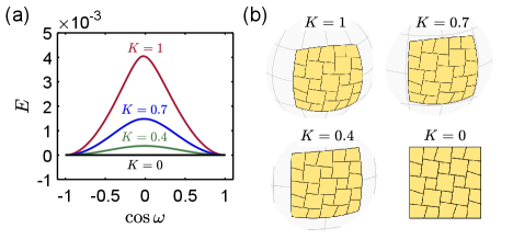
The evolution of the energy upon deployment can be simulated by a multispring model, in which the kirigami is represented by hinge-connected springs along the edges and diagonals of panels. In this model, the elastic energy of the deployed tessellations can be written as , where is the array of panel-vertex positions, the spring length numbered by the index , the rest length at the undeformed state, and the spring stiffness (set to be ). The deployed configurations are determined by incrementally increasing the kinematic parameter —defined by of the lower-left tessellation [Fig. 1(b)]—from the undeployed state. At each step, we minimize the energy taking positions of all the vertices as variables, which are constrained to form an SQK pattern, and enforce the opening angle (see Supplemental Material: Sec. VI.B [40]). Figure 3(a) demonstrates the energy curves of SQK shells perforated on a spherical square of fixed side length for different Gaussian curvatures. While decreasing from 1 to 0.4 [Fig. 3(b)], the energy barrier drops significantly. If , the SQK tessellation degenerates to a PQK tessellation, which is rigidly deployable (floppy) with zero energy of deformations. We illustrate the deployed configurations of these kirigami tessellations in Fig. S6. We additionally show the energy curves with deployed compatible states at in Fig. S7.
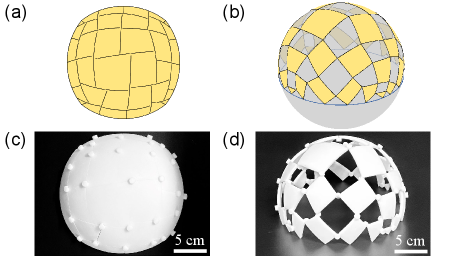
Shape-morphing structures. As a final demonstration for potential applications of our theorem, we address how to design the cutting patterns to achieve compatible deployed configurations with desired shapes. We start from a square SQK shell structure of side length and Gaussian curvature , and then optimize the locations of vertices via minimizing the distance between the deployed outer vertices and the boundary of a spherical dome of radius and height . Details of the optimization framework are given in Supplemental Material: Sec. VII [40]. Figure 4 demonstrates the shell structure (see Supplemental Material: Sec. IX [40] for fabrication details). The covering area of the undeployed pattern and the deployed dome can be calculated by and , respectively. Thus, the expansion ratio of the area is . According to Theorem 1, the deployed configuration is at an isolated compatible state, which is ideally rigid, so that it can form a stable structure for potential applications such as tents and roofs (see Movie 1 in Supplemental Material [40]). Moreover, shape-morphing mechanisms can be realized by PQK tessellations with different topologies [44].
Conclusion and discussion. In summary, we show that spherical quadrilateral kirigami tessellations can only be compatible at isolated configurations, whereas planar kirigami quadrilateral tessellations with parallelogram slits have infinite and continuous compatible states. We develop single-spring and multispring models to explicitly analyze and simulate the evolution of energy along the deployment paths for different values of Gaussian curvature, which characterizes the rigid-to-floppy transition. Since the deformation energy drops appreciably near the flat surface, the slightly curved kirigami shells are expected to be a promising candidate of pseudo-mechanisms, as those presented in Refs. [45, 46].
The compatibility theorem and its corollaries reveal the role of curvature in determining the deployment behaviors of kirigami systems. The effect of curvature on constrained morphology of stable structures can also be observed in various physical phenomena in nature such as the growth of nanoshells [47] and rigid colloidal crystals [48] on spherical substrates. More curvature-induced scenarios, such as the buckling of non-Euclidean kirigami shells—the counterpart of buckling-induced planar kirigami [10]—can be further investigated. Finally, the compatibility in our theorem relies purely on the size-independent geometry of the prescribed slits, so that the applicability is rooted in diverse materials and various scales.
Acknowledgements.
X.D., H.D. and J.W. thank the National Natural Science Foundation of China (Grant Nos. 11991033, 91848201, and 11521202) for support of this work. The authors thank Xiying Li and Yu Zou for assistance in 3D printing. We also thank Lu Lu and Paul Plucinsky for helpful discussions.References
- Blees et al. [2015] M. K. Blees, A. W. Barnard, P. A. Rose, S. P. Roberts, K. L. McGill, P. Y. Huang, A. R. Ruyack, J. W. Kevek, B. Kobrin, D. A. Muller, et al., Graphene kirigami, Nature 524, 204 (2015).
- Zhang et al. [2015] Y. Zhang, Z. Yan, K. Nan, D. Xiao, Y. Liu, H. Luan, H. Fu, X. Wang, Q. Yang, J. Wang, W. Ren, H. Si, F. Liu, L. Yang, H. Li, J. Wang, X. Guo, H. Luo, L. Wang, Y. Huang, and J. A. Rogers, A mechanically driven form of kirigami as a route to 3D mesostructures in micro/nanomembranes, Proc. Natl. Acad. Sci. U.S.A. 112, 11757 (2015).
- Tang and Yin [2017] Y. Tang and J. Yin, Design of cut unit geometry in hierarchical kirigami-based auxetic metamaterials for high stretchability and compressibility, Extreme Mech. Lett. 12, 77 (2017).
- Xu et al. [2017] L. Xu, T. C. Shyu, and N. A. Kotov, Origami and kirigami nanocomposites, Acs Nano 11, 7587 (2017).
- Callens and Zadpoor [2018] S. J. Callens and A. A. Zadpoor, From flat sheets to curved geometries: Origami and kirigami approaches, Mater. Today 21, 241 (2018).
- Hanakata et al. [2018] P. Z. Hanakata, E. D. Cubuk, D. K. Campbell, and H. S. Park, Accelerated search and design of stretchable graphene kirigami using machine learning, Phys. Rev. Lett. 121, 255304 (2018).
- Rafsanjani et al. [2019] A. Rafsanjani, L. Jin, B. Deng, and K. Bertoldi, Propagation of pop ups in kirigami shells, Proc. Natl. Acad. Sci. U.S.A. 116, 8200 (2019).
- Guo et al. [2021] X. Guo, X. Ni, J. Li, H. Zhang, F. Zhang, H. Yu, J. Wu, Y. Bai, H. Lei, Y. Huang, J. A. Rogers, and Y. Zhang, Designing mechanical metamaterials with kirigami-inspired, hierarchical constructions for giant positive and negative thermal expansion, Adv. Mater. 33, 2004919 (2021).
- Rafsanjani and Pasini [2016] A. Rafsanjani and D. Pasini, Bistable auxetic mechanical metamaterials inspired by ancient geometric motifs, Extreme Mech. Lett. 9, 291 (2016).
- Rafsanjani and Bertoldi [2017] A. Rafsanjani and K. Bertoldi, Buckling-induced kirigami, Phys. Rev. Lett. 118, 084301 (2017).
- Yang et al. [2018a] Y. Yang, M. A. Dias, and D. P. Holmes, Multistable kirigami for tunable architected materials, Phys. Rev. Mater. 2, 110601 (2018a).
- Tang et al. [2019] Y. Tang, Y. Li, Y. Hong, S. Yang, and J. Yin, Programmable active kirigami metasheets with more freedom of actuation, Proc. Natl. Acad. Sci. U.S.A. 116, 26407 (2019).
- An et al. [2020] N. An, A. G. Domel, J. Zhou, A. Rafsanjani, and K. Bertoldi, Programmable hierarchical kirigami, Adv. Funct. Mater. 30, 1906711 (2020).
- Cho et al. [2014] Y. Cho, J.-H. Shin, A. Costa, T. A. Kim, V. Kunin, J. Li, S. Y. Lee, S. Yang, H. N. Han, I.-S. Choi, and D. J. Srolovitz, Engineering the shape and structure of materials by fractal cut, Proc. Natl. Acad. Sci. U.S.A. 111, 17390 (2014).
- Sussman et al. [2015] D. M. Sussman, Y. Cho, T. Castle, X. Gong, E. Jung, S. Yang, and R. D. Kamien, Algorithmic lattice kirigami: A route to pluripotent materials, Proc. Natl. Acad. Sci. U.S.A. 112, 7449 (2015).
- Celli et al. [2018] P. Celli, C. McMahan, B. Ramirez, A. Bauhofer, C. Naify, D. Hofmann, B. Audoly, and C. Daraio, Shape-morphing architected sheets with non-periodic cut patterns, Soft Matter 14, 9744 (2018).
- Choi et al. [2019] G. P. Choi, L. H. Dudte, and L. Mahadevan, Programming shape using kirigami tessellations, Nat. Mater. 18, 999 (2019).
- Choi et al. [2021] G. P. T. Choi, L. H. Dudte, and L. Mahadevan, Compact reconfigurable kirigami, Phys. Rev. Research 3, 043030 (2021).
- Jin et al. [2020] L. Jin, A. E. Forte, B. Deng, A. Rafsanjani, and K. Bertoldi, Kirigami-inspired inflatables with programmable shapes, Adv. Mater. 32, 2001863 (2020).
- Shyu et al. [2015] T. C. Shyu, P. F. Damasceno, P. M. Dodd, A. Lamoureux, L. Xu, M. Shlian, M. Shtein, S. C. Glotzer, and N. A. Kotov, A kirigami approach to engineering elasticity in nanocomposites through patterned defects, Nat. Mater. 14, 785 (2015).
- Rafsanjani et al. [2018] A. Rafsanjani, Y. Zhang, B. Liu, S. M. Rubinstein, and K. Bertoldi, Kirigami skins make a simple soft actuator crawl, Sci. Robot. 3, eaar7555 (2018).
- Dias et al. [2017] M. A. Dias, M. P. McCarron, D. Rayneau-Kirkhope, P. Z. Hanakata, D. K. Campbell, H. S. Park, and D. P. Holmes, Kirigami actuators, Soft Matter 13, 9087 (2017).
- Note [1] Here we only consider stress-free stable configurations, which are determined solely by geometry.
- marie Belcastro and Hull [2002] S. marie Belcastro and T. C. Hull, Modelling the folding of paper into three dimensions using affine transformations, Linear Algebra Its Appl. 348, 273 (2002).
- Tachi [2009] T. Tachi, Generalization of rigid-foldable quadrilateral-mesh origami, J. Int. Assoc. Shell Spat. Struct. 50, 173 (2009).
- Feng et al. [2020] F. Feng, X. Dang, R. D. James, and P. Plucinsky, The designs and deformations of rigidly and flat-foldable origami, J. Mech. Phys. Solids 142, 104018 (2020).
- Castle et al. [2014] T. Castle, Y. Cho, X. Gong, E. Jung, D. M. Sussman, S. Yang, and R. D. Kamien, Making the cut: Lattice kirigami rules, Phys. Rev. Lett. 113, 245502 (2014).
- Castle et al. [2016] T. Castle, D. M. Sussman, M. Tanis, and R. D. Kamien, Additive lattice kirigami, Sci. Adv. 2, e1601258 (2016).
- Chen et al. [2016] B. G.-g. Chen, B. Liu, A. A. Evans, J. Paulose, I. Cohen, V. Vitelli, and C. D. Santangelo, Topological mechanics of origami and kirigami, Phys. Rev. Lett. 116, 135501 (2016).
- Yang and You [2018] Y. Yang and Z. You, Geometry of transformable metamaterials inspired by modular origami, J. Mech. Robot. 10, 021001 (2018).
- Chen et al. [2020] S. Chen, G. P. Choi, and L. Mahadevan, Deterministic and stochastic control of kirigami topology, Proc. Natl. Acad. Sci. U.S.A. 117, 4511 (2020).
- Wang et al. [2020] X. Wang, S. D. Guest, and R. D. Kamien, Keeping it together: Interleaved kirigami extension assembly, Phys. Rev. X 10, 011013 (2020).
- Jiang et al. [2020] C. Jiang, F. Rist, H. Pottmann, and J. Wallner, Freeform quad-based kirigami, ACM Trans. Graph. 39, 209 (2020).
- Grünbaum and Shephard [1987] B. Grünbaum and G. C. Shephard, Tilings and Patterns (Courier Dover Publications, 1987).
- Grima and Evans [2000] J. N. Grima and K. E. Evans, Auxetic behavior from rotating squares, J. Mater. Sci. Lett. 19, 1563 (2000).
- Sun et al. [2012] K. Sun, A. Souslov, X. Mao, and T. C. Lubensky, Surface phonons, elastic response, and conformal invariance in twisted kagome lattices, Proc. Natl. Acad. Sci. U.S.A. 109, 12369 (2012).
- Yang et al. [2018b] C. Yang, H. Zhang, Y. Liu, Z. Yu, X. Wei, and Y. Hu, Kirigami-inspired deformable 3D structures conformable to curved biological surface, Adv. Sci. 5, 1801070 (2018b).
- Ko et al. [2008] H. C. Ko, M. P. Stoykovich, J. Song, V. Malyarchuk, W. M. Choi, C.-J. Yu, J. B. Geddes Iii, J. Xiao, S. Wang, Y. Huang, et al., A hemispherical electronic eye camera based on compressible silicon optoelectronics, Nature 454, 748 (2008).
- Rao et al. [2021] Z. Rao, Y. Lu, Z. Li, K. Sim, Z. Ma, J. Xiao, and C. Yu, Curvy, shape-adaptive imagers based on printed optoelectronic pixels with a kirigami design, Nat. Electron. 4, 513 (2021).
- [40] See Supplemental Material for details of the compatibility formulations, energetic calculations, and inverse design optimizations.
- Note [2] We focus on patterns with a compact configuration. There are also kirigami patterns with no compact states, for which the cuts are voids of actual area, such as the lattice kirigami [27] and rhombi-slit kirigami [46].
- Note [3] In our discussion, the term tessellation stands for kirigami patterns with and ; we refer to patterns with or as kirigami strip, which are always rigidly deployable (see Fig. S1 and Supplemental Material: Sec. I [40]).
- Todhunter [1863] I. Todhunter, Spherical Trigonometry, for the Use of Colleges and Schools: With Numerous Examples (Macmillan, 1863).
- Dang et al. [2021] X. Dang, F. Feng, H. Duan, and J. Wang, Theorem for the design of deployable kirigami tessellations with different topologies, Phys. Rev. E 104, 055006 (2021).
- Singh and van Hecke [2021] N. Singh and M. van Hecke, Design of pseudo-mechanisms and multistable units for mechanical metamaterials, Phys. Rev. Lett. 126, 248002 (2021).
- Zheng et al. [2021] Y. Zheng, I. Niloy, P. Celli, I. Tobasco, and P. Plucinsky, A continuum field theory for the deformations of planar kirigami (2021), arXiv:2108.00336 .
- Bao et al. [2011] H. Bao, W. Peukert, and R. K. Taylor, One-pot colloidal synthesis of plasmonic patchy particles, Adv. Mater. 23, 2644 (2011).
- Meng et al. [2014] G. Meng, J. Paulose, D. R. Nelson, and V. N. Manoharan, Elastic instability of a crystal growing on a curved surface, Science 343, 634 (2014).