The alignment of the C3 Accelerator Structures with the Rasnik alignment system
Abstract
The Rasnik 3-point alignment system, widely applied in particle physics experiments and in the instrumentation of gravitational wave experiments, can be used as N-point alignment system by ’leap frog’ N individual 3-point systems. The conceptual implementation of Rasnik chains in C3 is presented. Then, the proper operation of a laser diode and a CMOS image sensor in liquid nitrogen has been verified. Finally, next plans for testing a small but complete system, immersed in liquid nitrogen, are presented.
1 The Rasnik 3-point alignment system
The first Red Alignment System Nikhef (Rasnik) was developed in 1983 for the alignment of the muon chambers in the Muon Spectrometer of the L3 experiment at CERN [1]. As sensor, 4-quadrant photodiodes were used. In 1993, CMOS image sensors became available, and Rasnik evolved into a system in which a back-illuminated coded mask is projected, by means of a positive singlet lens, onto the image sensor. Since 2005, some 8000 of these Rasnik system are flawlessly operational in the ATLAS experiment at CERN. With these Rasnik systems, composed from low-cost, commercially available components, the 2D alignment of three points can be measured with a spatial resolution of 1 nm. The best resolution power of 7 pm/Hz was obtained with an image frame rate of 250 Hz [2].
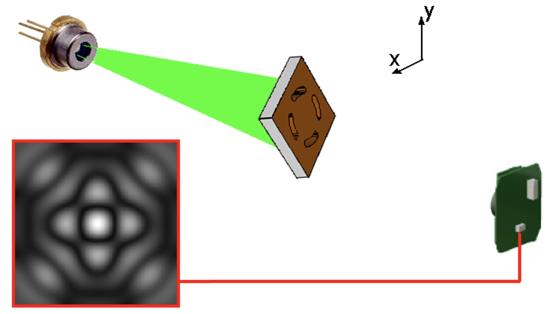
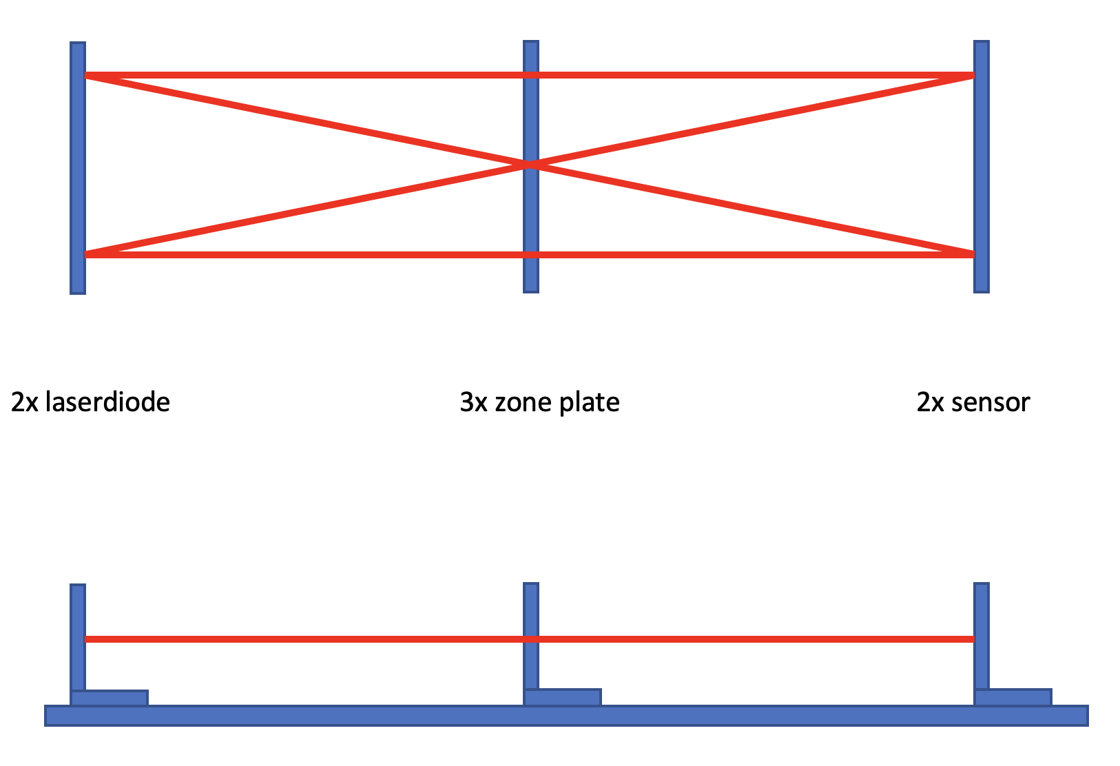
For the alignment of active beam elements of future CLIC and ILC linear colliders, systems with a span between the image sensor and the mask of a Rasnik system larger than 20 m are required. The diameter and focal length of the required lens become impractically large, and its replacement by a zone plate was considered. In the so-called RasDif system, depicted in figure 1, the back-illuminated coded mask is replaced by a monochromatic point-like light source generating spherical waves onto the zone plate. This results in a typical diffraction pattern onto the image sensor: the position of this pattern on the sensor is a measure for the 3-point alignment of light source, zone plate and image sensor, respectively.
2 Rasnik in Liquid Nitrogen
So far, Rasnik systems have been operated in ambient air and in vacuum. In C3, Rasnik must operate in ambient air, in vacuum and in boiling liquid nitrogen (LN2), at 79 K [3] [4][5]. Given the index of refraction of LN2 of 1.20, lenses can not be applied because a sharp image in LN2 will be out of focus in vacuum. This is the main reason why the RasDif system is applied.
Laser diodes were tested to operate in LN2: they work, albeit that their supply voltage of 2 V at 293 K usually needs to be raised to 6 V when immersed in LN2. With a current of 10 mA, the heat dissipation causes local boiling and therefore the formation of bubbles. The glass cover seal provides local thermal shielding, so bubble formation in the critical light exit zone is locally reduced. The following three laser diodes were found to be LN2 proof: Laser Components ADL65074TR, Laser Components ADL65055TL, and ROHM RDL65MZT7. The long term stability of the sealed package in vacuum, in ambient air and in LN2 remains to be verified.
Modern CMOS image sensors are known not to operate below 90 K. In 2014, two groups tested CMOS image sensors in populair low-cost webcams by simply immersing them in LN2, while reading them out via their USB connection [6, 7]. Eventually, two webcams were found to operate unaffected in LN2: the Floureon "car reversing camera", and the Microsoft HD-3000 Model 1456 (or earlier). The latter can still be acquired, and proper operation in LN2 has been recently confirmed, including a cold start, avoiding the self heating of the circuitry due to dissipation. For the coming R&D projects, some 8 of these image sensors will be applied in experimental set-ups.
3 Rasnik in C3
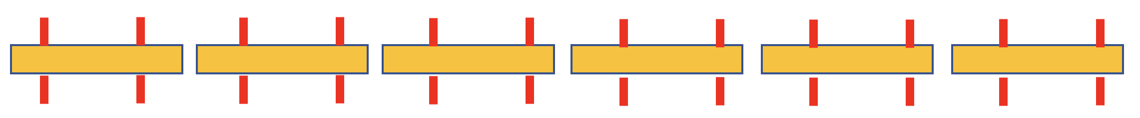
In figure 2, the assembly of chain plates is shown: the position, in X and Y, of any plate with respect to any other plate is known. The alignment of Accelerator Structures and Quads of C3 can be realised by linking them with chain plates.
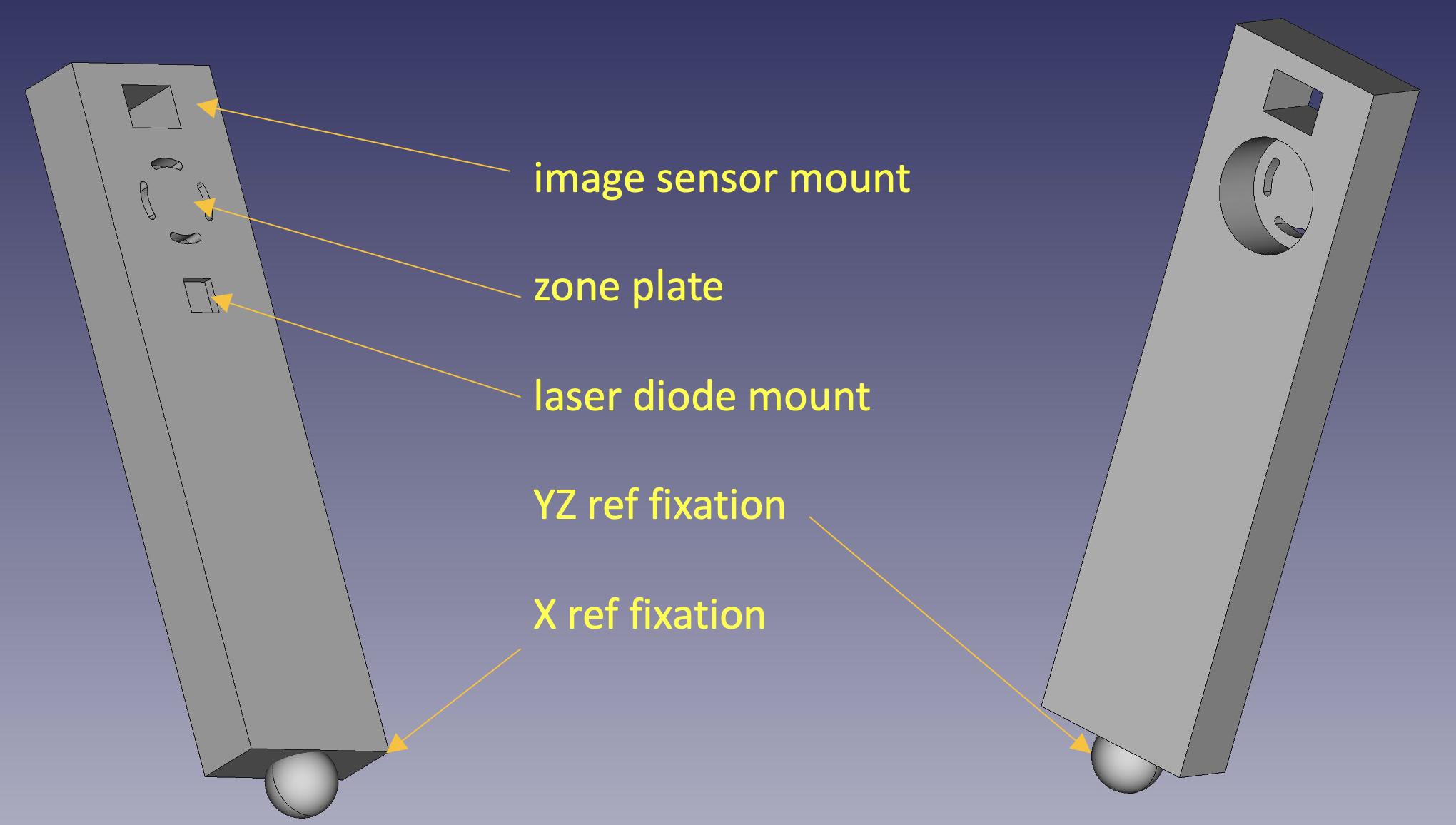
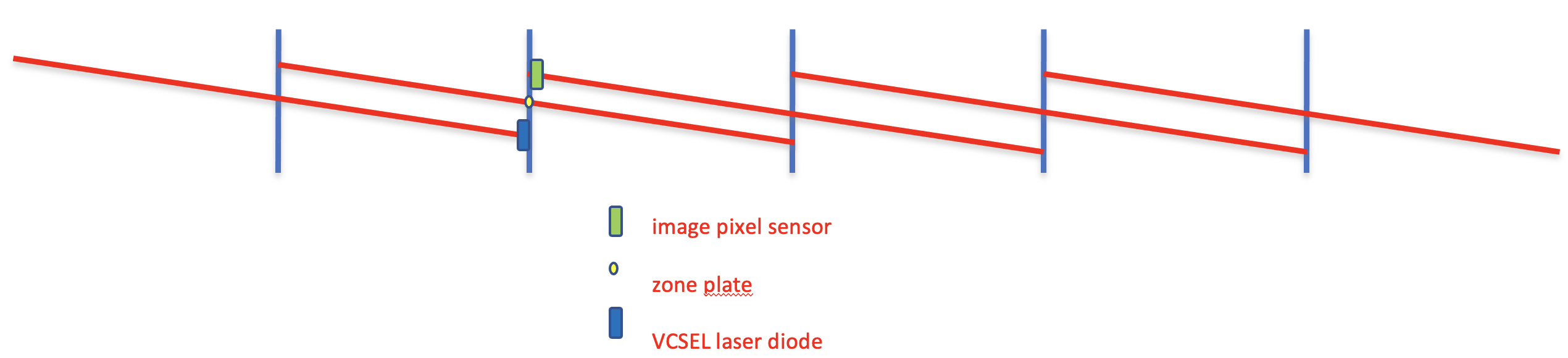
In C3, the chain plate takes the form of a stick, shown in figure 3. In a chain, all Sticks are practically identical: individual differences are known after a calibration procedure. On a Stick a CMOS image sensor chip is fixed, a pattern forming a zone lens is milled out, and laser diode is mounted. A Stick is mounted, using its mechanical interface, onto an Accelerator Structure or a Quad, the latter being an assembly of a static quadrupole magnet and a Beam Position Monitor.

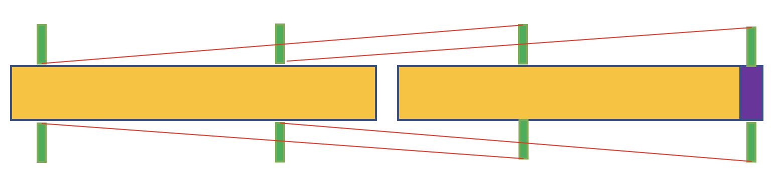
A first approach towards the application of Rasnik in the alignment of the 1 m long copper Accelerator Structures is shown in figure 4. Although there is some redundancy, the Rasnik data does not cover all 6 degrees of freedom of the Structures. Since two adjacent Structures are confined by means of a raft structure, this may be acceptable. In figure 5 the number of Sticks is doubled, providing the redundant measurement of all 6 degrees of freedom of all Structures.
4 The effective precision of a chain of Rasnik systems
The error of a 3-point Rasnik system is defined as the variation in the sagitta, defined as the distance, in X and Y, of the optical centre of the zone plate to the optical axis, being the line through the optical centres of the laser source and the image sensor. Assuming that the medium is homogeneous, light propagates in a straight line. For simple systems using low cost laser diodes and image sensors extracted from popular webcams, the (Gaussian) noise in the sagitta measurement due to quantum fluctuations in light falling onto pixels, can be as good as 100 nm. With modern low-cost image sensors, the frame rate of 100 Hz results in a resolution power of 10 nm/ which is the equivalent of 100 nm resolution of one measurement per second. With a custom designed image sensor optimised for application in C3, a resolution power of 5 nm/Hz should be within reach [1, 2, 12].
The 2D position of a Quad or Accelerator Structure is transferred to Rasnik by means of Sticks. The mechanical interface between the Stick and the object onto which it is mounted is associated with a set up error of order 1 µm if state-of-the-art suspension mechanics are applied. In addition, the positions of the optical centres of laser source, zone plate and image sensor with respect to the mechanical interface, which are measured in a calibration procedure (see Calibration of the Sticks) are subject to a similar offset error of 1 µm.
Combining the two errors together, each Rasnik data point from a particular system is subject to an offset error of order 1 µm, constant in time, and a random Gaussian error much smaller than 0.1 µm.
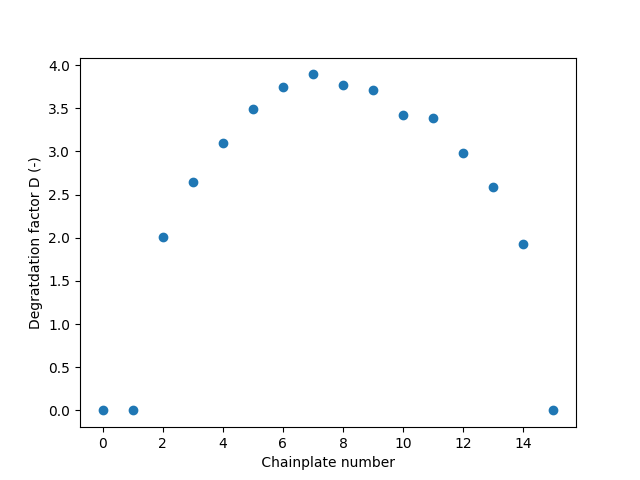
Figure 6 shows the errors associated with a chain of = 16 Rasnik systems. In this calculation the positions of chainplate 0, 1 and 15 are fixed, and the positions of the in-between chainplates are calculated from the MonteCarlo simulated Rasnik data, assuming a spatial resolution of 1.0 (RMS, unitless) for each system. The largest error occurs, as expected, at the central plate since it is far away from the fixed chainplates. The largest spatial error equals times the sagitta error of a single Rasnik system, where D = .
The Quarter Cryogenic Module (QCM) will be equipped with 4-fold Rasnik chains placed at both sides. Given the offset error of an individual Rasnik system of 1 µm, and a degradation factor = 2, the relative positions of the two Accelerator Structures and the Quad will be known within 1.5 µm after the eight calibrated Sticks are placed.
In C3, a SuperSector includes 728 Accelerator Structures. If these are equipped with two continuous Rasnik chains, the largest uncertainty in the middle of each chain is / = 19 µm. By adding Rasnik systems on Sticks 1, 364 and 728, this largest error can be reduced by a factor . As long as the light path area, now confined by the raft’s main beams, is respected, there is room for improvement.
5 Conclusions and future plans
One CMOS image sensor has been found and identified to operate flawlessly immersed in LN2 at 77 K. With some 10 of these sensors, demonstrations of complete Rasnik systems, in air and immersed in LN2, could be performed, within a year. Most likely, new CMOS image sensors will become available, capable to operate in a cryogenic environment, thanks to commercial interest. The proper operation of laser diodes in LN2 has been certified.
By applying Rasnik instead of a system in which the local position of a stretched wire is determined by multiple Wire Position Sensors (WPS) [13],[14], severe problems are avoided: no risk of a hard-accessible broken wire, no error in the vertical coordinate due to uncertainties in wire sag, and no risk of variations in the wire position due to flowing LN2 medium.
Other benefits of using Rasnik alignment systems are:
-
•
electronics: benefits of using only off-the-shelf USB Muxs, CPUs or GPUs;
-
•
precision is limited by (mechanical) offset; intrinsic 2D spatial resolution of 10 nm;
-
•
mechanical noise, due to bubble formation and flow of LN2 can be well studied given the excellent spatial resolution power;
-
•
no scale calibration required;
-
•
low cost: € 30 per system, excluding readout;
-
•
no drift: 1/f noise is not measurable;
-
•
radiation-proof components can be selected.
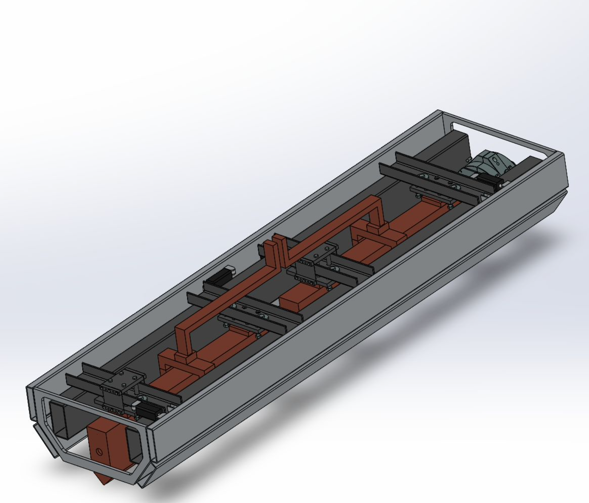
Figure 7 shows the InPlaneDemo setup. It includes two parallel and two diagonal Rasnik systems. With this, performance-limiting effects of Rasnik in LN2 can be studied in detail:
-
•
the formation of N2 gas bubbles on the surface of the heat-dissipating laser diodes and CMOS image sensors;
-
•
local variations in the index of refraction of LN2 due to the laminar or turbulent flow, and due to convection near the warmer laser diodes and CMOS image sensors;
-
•
mechanical noise due to bubble formation and bubble transport in LN2. Here the 10 nm spatial resolution and a high frame rate of Rasnik will be useful;
-
•
the long-term quality degradation of laser diodes and CMOS image sensors.
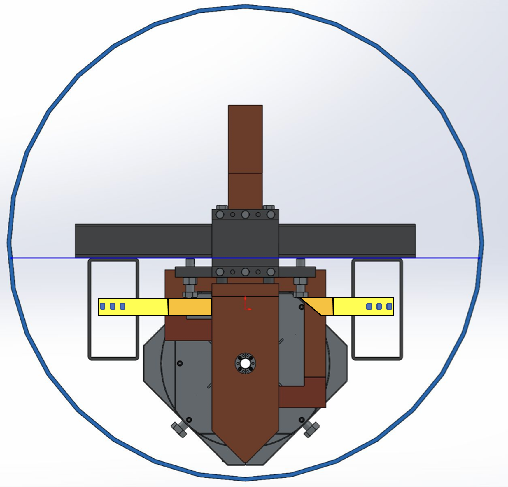
Rasnik for the Quarter Cryogenic Module (QCM). Figure 8 shows the basic raft unit: an assembly of two sequential Accelerator Structures, one Quad module, waveguides and a frame keeping these items in their proper position. Placed in a cryostat filled with LN2, the functionality of QCM can be fully tested [15]. For this, the relative positions of the Quad and the Accelerator Structures can be monitored with Rasnik, as is shown in figures 9 and 10. The optical paths are confined in the raft’s construction bars. Since only the laser diodes and image sensors dissipate their power there is little bubble formation inside these bars, and the LN2 flow in the bar is expected to be directed in Z, and laminar. Variations in the index of refraction in the X and Y directions should be small.
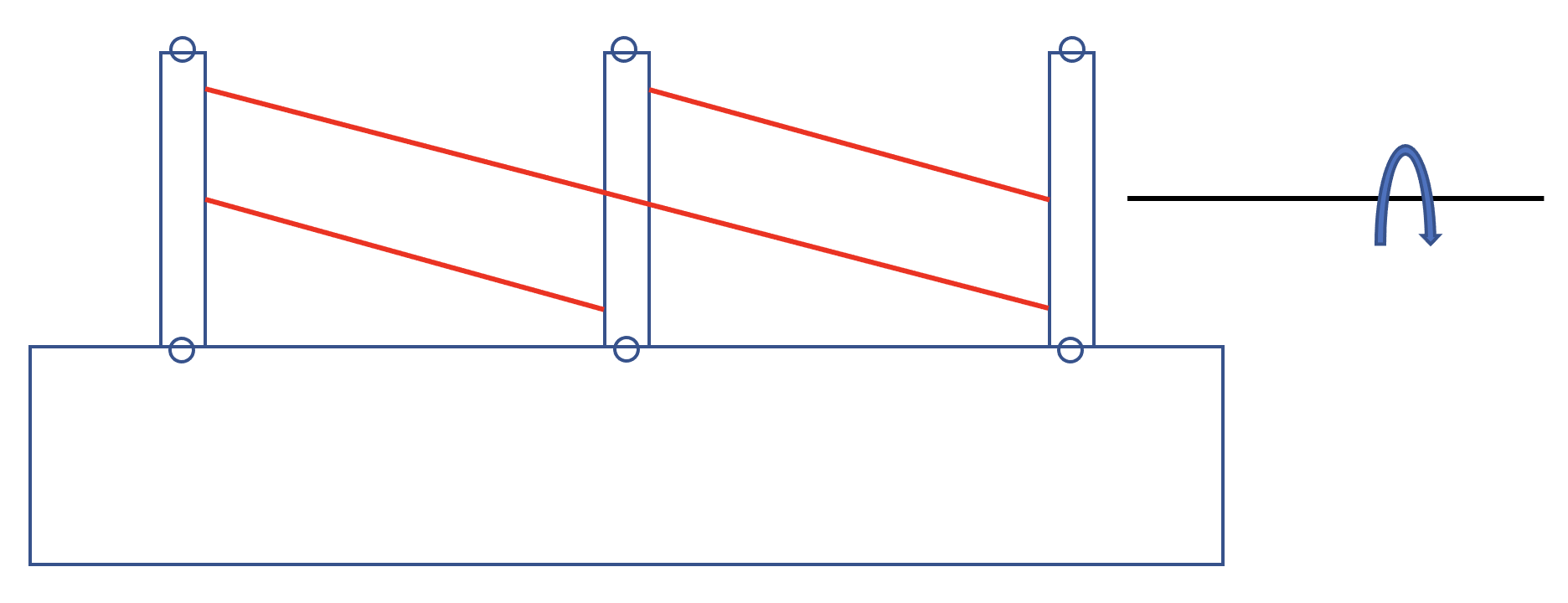
Calibration of the Sticks. With calibrated Sticks, the 6D relative positions of the two Accelerator Structures and the Quad in the QCM are known as soon as the eight Sticks are mounted in position. With the Calibration Station, shown in figure 11, placed in a normal lab environment, the 3x X and 3x Y coordinates of the source, zone plate and sensor, respectively, with respect to the mechanical reference, can be obtained for each individual Stick [16]. After measuring the alignment error of the Station, the calibration of any Stick is obtained by placing sets of three Sticks on the station, such that each Stick will pass at least one time the left-, middle- and right position on the Station.
Acknowledgments
We thank Nikhef for facilitating tests of crucial components in their dewar, and we are grateful to Amolf to provide us with LN2. We thank Oscar van Petten for producing mechanical supports, Berend Munneke for his practical assistance, and Nico Rem for keeping us working safe.
References
- [1] M. Beker, G. Bobbink, B. Bouwens, N. Deelen, P. Duinker, J. van Eldik, N. de Gaay Fortman, R. van der Geer, H. van der Graaf, H. Groenstege, R. Hart, K. Hashemi, J. van Heijningen, M. Kea, J. Koopstra, X. Leijtens, F. Linde, J.A. Paradiso, H. Tolsma, and M. Woudstra. The Rasnik 3-point optical alignment system. Journal of Instrumentation, 14(08):P08010–P08010, aug 2019. DOI:10.1088/1748-0221/14/08/P08010
- [2] : The ultimate performance of the Rasnik 3-point alignment system, Nuclear Inst. and Methods in Physics Research, A 1050 (2023) 168160
- [3] Sridhara Dasu et al.: Strategy for understanding de Higgs physics: the cool copper collider, 2020 arXiv 2203.07646
- [4] Mei Bai et al.: A "Cool" Route to the Higgs Boson and Beyond, 2021 arXiv 2110.15800
- [5] Emilio Nanni et al.: The C3 Demonstration Research and Development Plan, 2022 arXiv 2203.09076
- [6] Nicola McConkey et al.: Cryogenic CMOS Cameras for High Voltage Monitoring in Liquid Argon, Journal of Instrumentation 12(03), December 2016 DOI:10.1088/1748-0221/12/03/P03014
- [7] K. Mavrokoridis, F. Ball, J. Carroll, M. Lazos, K. J. McCormick, N. A. Smith, C. Touramanis and J. Walker: Optical Readout of a Two Phase Liquid Argon TPC using CCD Camera and THGEMs, JINST 9 (2014) P02006
- [8] G. Ghibaudo and F. Balestra: Low Temperature Characterization of Silicon CMOS devices, Microelectron. Reliab. 37(1997) 9, 1353-1366.
- [9] Z. Hongliang and L. Xinghui: A low-power cryogenic analog to digital converter in standard CMOS technology, Cryogenics 55-56 (2013) 79-83.
- [10] D. Gong et al. [LBNE Collaboration]: The Cryogenic Performances of Specific Optical and Electrical Components for a Liquid Argon Time Projection Chamber, Phys. Procedia 37 (2012) 1654.
- [11] R. L. Patterson, A. Hammoud and M. Elbulu Assessment of electronics for cryogenic space exploration missions, Cryogenics 46 2-3 (2006) 231-236.
- [12] J.V. van Heijningen. Precision Improvement in Optical Alignment Systems for Linear Colliders. M.Sc. thesis, Nikhef, Amsterdam and Delft University of Technology, 2012
- [13] H. Manaud Durand et al. Stretched wire offset measurements: 40 years of this technique at CERN. Presented at the 10th International Workshop on Accelerator Alignment, KEK, Tsukuba, Japan, 11–15 February 2008.
- [14] Juha Kemppinen, Vivien Rude, Hélène Mainaud Durand, Jouni Mattila. CLIC pre-alignment: status and remaining challenges. Measur.Sci.Tech. 32 (2021) 11, 115015 (Aug 3, 2021)
- [15] Martin Breidenbach et al.: C3, the Cryomodule and Cryogenics. JINST, these Proceedings
- [16] H. van der Graaf: The calibration of the ATLAS muon spectrometer projective alignment systems ATL-MUON-2004-024, CERN, Geneva, Switzerland (2004).