Task Generalization with Stability Guarantees via
Elastic Dynamical System Motion Policies
Abstract
Dynamical System (DS) based Learning from Demonstration (LfD) allows learning of reactive motion policies with stability and convergence guarantees from a few trajectories. Yet, current DS learning techniques lack the flexibility to generalize to new task instances as they ignore explicit task parameters that inherently change the underlying trajectories. In this work, we propose Elastic-DS, a novel DS learning, and generalization approach that embeds task parameters into the Gaussian Mixture Model (GMM) based Linear Parameter Varying (LPV) DS formulation. Central to our approach is the Elastic-GMM, a GMM constrained to SE(3) task-relevant frames. Given a new task instance/context, the Elastic-GMM is transformed with Laplacian Editing and used to re-estimate the LPV-DS policy. Elastic-DS is compositional in nature and can be used to construct flexible multi-step tasks. We showcase its strength on a myriad of simulated and real-robot experiments while preserving desirable control-theoretic guarantees. Supplementary videos can be found at https://sites.google.com/view/elastic-ds.
Keywords: Stable Dynamical Systems, Reactive Motion Policies, Learning from Demonstrations, Task Parametrization, Task Generalization
1 Introduction
With advanced development in robotics and autonomous systems in the past decades, the opportunities and demands for more complex physical human-robot interaction (pHRI) in our everyday unconstrained environments are rising; thus, it is critical for robots to be adaptive, compliant, reactive, safe and easy to program [1, 2, 3]. In many cases, robots will need to acquire new skills to satisfy task requirements in an ever-changing environment. It is usually difficult for non-experts to program robots for complex motion tasks and even tedious for experts to reprogram them when task requirements change. A straightforward and intuitive approach for robots to develop new skills is through Learning from Demonstration (LfD) [4, 5, 6, 7, 8]. This paradigm allows robots to acquire skills, typically encoded or defined in literature as action policies, motion policies, or imitation policies, directly from motion examples provided by humans or even other robots, mirroring a teacher-student relationship.
In recent years, significant progress has been made in using LfD to learn complex and diverse motion tasks. However, many focused on learning and executing tasks from static or unchanged scenarios/environments/contexts, which could lead to failures when faced with out-of-distribution cases. From the machine learning perspective, this is the covariate shift issue that exists in many supervised learning related tasks, especially in the behavior cloning (BC) approach [7, 9]. By providing a fixed training dataset beforehand, the LfD algorithm will learn a policy that performs well for the training dataset but could fail to generalize to unseen input during deployment. The learned policy will become invalid due to the change of distribution. Hence, instead of memorizing human demonstrations for one scenario, the robot should be able to adapt and generalize to novel scenarios with satisfactory performance, given the same task objective.

The Trilemma - Generalization or adaptation abilities are particularly important to enable robots to perform effectively in dynamic environments. There are many attempts at generalization with methods like BC [10], Inverse RL (IRL) [11, 12, 13], Meta-Learning [14], Multi-Task Learning [15], Transfer Learning [16], Multi-Task Reinforcement Learning [17], Lifelong Learning [18, 19, 20], and continual learning [21]. However, the aforementioned approaches have no emphasis on providing control-theoretical guarantees on the learned policies, such as stability, boundedness, and convergence, all of which are critical for safe pHRI. On the other hand, the Dynamical System-based (DS) motion policy approach [3] offers many advantages such as reactivity, motion-level adaptation, and, most importantly, stability guarantees; and can be learned from only handful of demonstrations ensuring minimal human effort [22, 23]. However, due to the closed-form and offline learning nature of DS-based motion policies, they have no flexibility for generalizing to novel environments as they ignore explicit task parameters that inherently change the underlying trajectories that shape the DS vector fields. This limits their generalization capability and adoption as low-level policies. Hence, invoking the no free lunch theorem, we posit that the state-of-the-art currently suffers from the generalization vs. stability vs. effort trilemma.
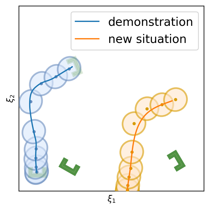
Goal In this work, we seek to alleviate this trilemma by proposing an LfD approach that has i) stability guarantees, ii) the flexibility to generalize motions across novel scenarios, while iii) requiring minimal human effort during learning and adaptation/generalization, as depicted in Figure 1.
Related Work The number of techniques that exist for LfD/IL is vast [6, 4, 7, 8]. This work follows the BC approach, which learns a policy that maps states (state-action pairs, trajectories, and other contexts are also used) to control inputs [24]. DAgger [25] addressed distribution shift issues with online interactions/corrections. Whereas the generative adversarial learning framework [26] randomly explores for corrections that bring the policy close to the demonstrated distribution. These approaches offer generalization in terms of distribution shift but require either constant human effort or lots of data and computation and hold no control-theoretic guarantees on the learned policy. The recently introduced TaSIL (Taylor Series IL) framework introduces a simple augmentation to the BC loss such that the trained policy is robust to distribution deviations by ensuring incremental input-to-state stability, also benefiting from reduced sample-complexity [27]. Nevertheless, it cannot generalize to novel task instances/environments not seen during training. A Probably Approximately Correct (PAC)-Bayes IL framework was introduced in [10] that computes upper bounds on the expected cost of policies in novel environments. Prior works also focus on explicit skill generalization for novel environments or task instances, such as multitasking learning [28, 29, 30, 31], meta-learning [14, 32]. While capable of generalizing learned tasks to different environments, these works require a considerable amount of offline/online training and require excessively large DNNs, which cannot be used in a reactive manner nor offer any form of control-theoretic guarantees.
A significant body of work tackles the generalization problem by emphasizing task parametrization (TP) as relevant task frames in assigned to relevant objects in demonstrations, like TP-GMM [33, 34], TP-DMP [35], task invariants [36, 37] and environmental constraints [38]. Other works focus on the motion policy parameter perspective, such as adapting explicit start and goal positions in movement primitives [39], conditioning on probability distributions like the Probabilistic Movement Primitives (ProMPs) for different via-points [40] and geometric descriptor [41]. While such works have demonstrated the ability for task generalization, few provide real-time reactive motion and stability guarantees, and most of them rely on the availability of demonstrations in different contexts or environments to extract the relevant task parameters for generalization.
Approach We propose a zero-shot approach for generalizing motion policies to novel scenarios while guaranteeing control-theoretic properties for safe deployment in pHRI. To achieve stability, we adopt the DS-based LfD paradigm [3] that learns motion policies as time-invariant nonlinear DS with Lyapunov stability guarantees. To achieve generalization, we follow the task-parametrization perspective [33, 34, 35] and propose to embed relevant task frames directly into the DS policy. While several neural network (NN) based formulations for stable DS motion policies exist, such as neurally imprinted vector fields [42], DNN via contrastive learning [43], diffusion models [44], and euclideanizing flows [45]; given their black-box nature it is not straightforward to embed such task parameters into these formulations. Further, NN approaches need multiple demonstrations to encode the stable DS properly. To achieve minimal data, compute and human effort during learning, we adopt the Gaussian Mixture Model (GMM) based Linear Parameter Varying (LPV-DS) formulation [22, 3] which has shown to be computationally efficient and capable of learning stable vector fields of complex motions from single demonstration [23]. Finally, we take inspiration from elastic bands [46] and trajectory editing [47] and propose a novel approach to generalize the GMM-based LPV-DS to novel scenarios without new demonstrations, referred to as Elastic-DS.
Contributions We introduce the Elastic-DS formulation as a solution to the LfD trilemma (See Figure 2). The Elastic-DS is constrained to a set of task parameters described as geometric descriptors representing the invariant features of a task (e.g., object, via-point, or target configurations). It is capable of efficiently generating novel DS policies upon task parameter changes without requiring new data or human input for single, multi-step tasks and the composition of new tasks via DS stitching.
2 Problem Statement
Let be a set of demonstration trajectories collected from kinesthetic teaching for a task, where , represent the kinematic robot state and velocity vectors at time , respectively, for the n-th trajectory with length . In this work, we consider to be the end-effector Cartesian position. Let be a first-order DS that describes a motion policy in state space. Given , the goal is to infer such that any point in the state space leads to a stable attractor , with described by a set of parameters and
| (1) |
Usually, such DS motion policies are learned in an offline manner and fixed for the execution phase [23]. The main contribution of this work is to introduce an update stage that parametrizes the system further, allowing the motion policies to adapt and generalize to new tasks, as shown in Figure 2.
Task Parameters A task is defined as a combination of multiple trajectories where each of them is grounded on a geometric constraint descriptor set , describing the two endpoint poses. Let be generalization parameters in the state space conditioned on the geometric descriptors . As changes, will change accordingly to generate a new set of DS to reach with the correct poses. In this work, the geometric descriptors is assumed to be known or given during demonstrations. However, it could come from various upstream sources such as human specifications [23] or generative segmentation algorithms [48].
Motion Policy We propose the following motion policy for task-parameterized generalization:
| (2) |
where is an activation function determining the sequence of execution for DSs describing a multi-step sequential tasks. Hence, given with the same behavior and geometric descriptor configurations, our approach finds that will generate new DS motion policies with i) stability guarantees with respect to their corresponding attractors , and ii) the flexibility to achieve the same task with new geometric constraint descriptor configurations.
3 Preliminaries: -GMM and LPV-DS Motion Policy [22]
The GMM-based LPV-DS [22] motion policy has the following formulation,
|
|
(3) |
where is the state-dependent mixing function that quantifies the weight of each linear time-invariant (LTI) system . denotes the probability of observation from the -th Gaussian component parametrized by , and represents the prior probability of an observation from this particular component and the a posteriori probability is
| (4) |
Intuitively, Eq. 9 fits a mixture of linear DS to a complex non-linear trajectory, with ensuring the smoothness of the reproduced trajectories. Hence, each Gaussian component must be placed on quasi-linear segments of . With -GMM, the optimal number of linear DS for a given can be automatically inferred.
Stability To guarantee global asymptotic stability of Eq. 9, a Lyapunov function with , is used to derive the stability constraints in Eq. 9. Minimizing the fitting error of Eq. 9 with respect to demonstrations subject to constraints in Eq. 9 yields a non-linear DS with a stability guarantee via a Semi-Definite Program (SDP) [22]. Implementation details are provided in Appendix A.
4 Elastic-DS
4.1 Elastic-GMM
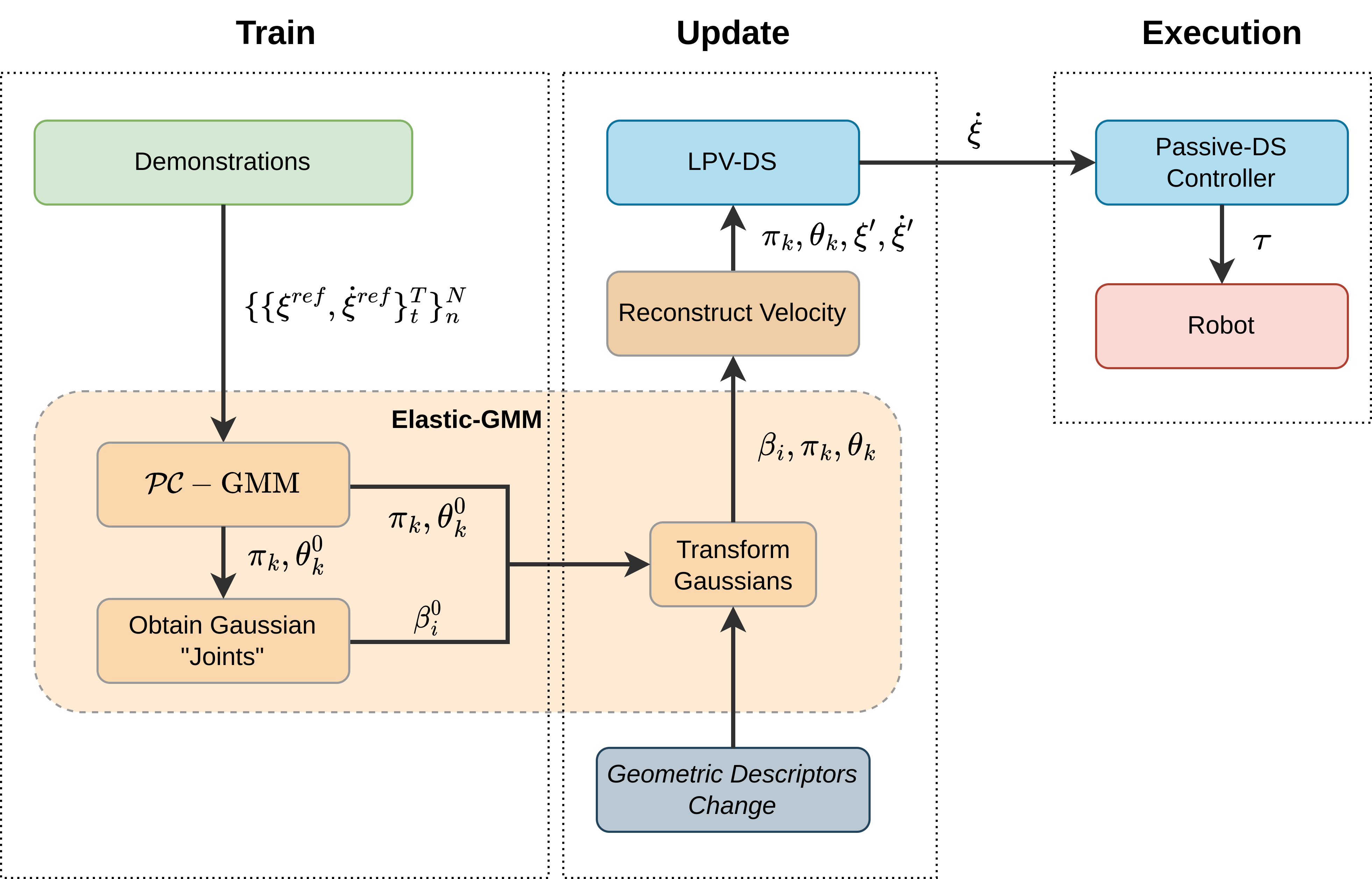
To adapt generalization parameters for the corresponding spatial change in the geometric descriptors , we introduce Elastic-GMM as the core component of augmenting LPV-DS (Eq. 9) into Elastic-DS (Eq. 2). Figure 2e shows the pipeline of Elastic-DS. During the training stage, we use -GMM [22] to obtain a set of initial Gaussian parameters as well as the initial . The update stage will produce the updated Gaussian parameters as well as the updated , which are key way-points in the state space. A trajectory will be generated based on the key points to specify the velocity for the DS after the update. With the new Gaussian parameters and the new velocity information, an updated LPV-DS can be learned. If further updates happen in the environment, we can directly update LPV-DS using the transform without re-estimating the GMM, which avoids a time-consuming stage. During the execution, a passive-DS controller [3] will take the newest LPV-DS output velocity to generate the corresponding joint torque for the robots. The upcoming section will discuss each key component in detail. The algorithm is in Appendix G.
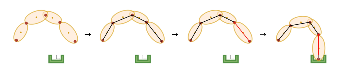
4.1.1 GMM Chain
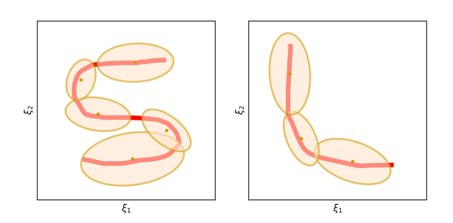
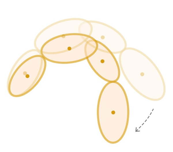
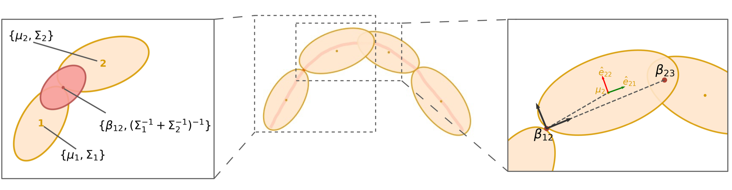
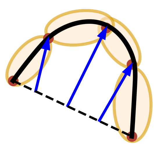
Following the LPV-DS pipeline, the demonstration trajectory is encoded into GMM using -GMM [22]. As shown in Figure 3a, a trajectory is extracted and simplified into a chain of Gaussians links. In the update stage (Figure 2e), we transform the spatial relationships among the Gaussians to achieve task adaptation. Imagine an analogy of the Gaussian chain being a robot arm, which could be rotated around each joint to achieve a specific geometric configuration as shown in Figure 3b. Note the robot arm analogy is on the end-effector trajectory instead of the actual robot arm. The generalization parameters are the joints between each pair of the neighboring Gaussians, which describes the spatial relationship between the neighbors. After the -GMM step, we can obtain the initial and later update the to to achieve transform. The joint of two Gaussian, which is the , is the mean of the product between them as described by the picture on the left in Figure 3c, which could be obtained by,
| (5) |
where and are the mean and covariance of the Gaussians and . To complete the robot arm analogy, we also need to determine the links position and orientation with respect to the joints. Figure 3c depicts the Gaussian mean position and orientation (described by the eigenvectors of the covariance matrix ) with respect to the frame at the last joint with the x-axis pointing towards the next joint (in the direction of the demonstration). All of the above are constructed as the initial condition, in which no update is involved yet. Later when the states of the generalization parameter change, we will recover the same transformation of the mean and covariance with respect to the corresponding . Before introducing the approach to obtain the new joint positions we provide a brief summary of the Laplacian editing approach [49, 47].
4.1.2 Laplacian Editing Primer
Laplacian Editing allows directly modifying an existing trajectory defined by waypoints while capturing local properties. First, we convert the waypoints in cartesian space into Laplacian coordinates with the graph Laplacian matrix [47],
| (6) |
where are a set of neighbor points for waypoint , and is a weight set to 1 for this work. One can obtain , where is a concatenation of the Laplacian coordinate for each waypoint . The matrix can be singular, so one can impose constraints on the system when solving for new waypoints to achieve editing [47].
4.1.3 Transform Gaussians with Constraints
The initial joints are converted into the Laplacian coordinate, which constructs a least-square objective as in Section 4.1.2. Then, we align the first link (formed by and ) and the last link (formed by and ) with the geometric descriptor , which forms the constraints for the least-square formulation. When solving for this optimization, the other will adjust based on the Laplacian objective, softly preserving local position properties,
| (7) |
where and are the same as in Section 4.1.2. represents the frame transformation from to . The solution of this optimization will produce new joints positions . After that, the link position and orientation (which are the Gaussians’ means and covariances), as well as the scale, are recovered using the recorded from the previous section. The orientation of the Gaussian is determined by the eigenvector shown in red and green in Figure 3c. Each orientation will remain fixed with respect to the last joint frame ( in Figure 3c). If a rotation happens to the last joint frame, the Gaussian frame associated with the last joint will be moved together in the global frame but remain the same in the last joint frame. The scale is determined by the change from the original distance between each pair of neighboring joints, which scales the eigenvalues of the Gaussians’ covariances. Referring back to the flowchart in Figure 2e, this section outputs the updated joint positions and updated GMM parameters ( stay unchanged).
4.2 Create Velocity Profile
Depending on the new task constraints, the velocity requirement could be different from the original demonstration. Therefore, this approach offers the opportunity to modify the velocity by regenerating a trajectory along the Gaussians joints as the waypoints. There are many ways to achieve this with known waypoints, such as splines or minimum jerk trajectory. We provide a simple example of using Laplacian Editing to generate a new trajectory. First, we connect and to form a linear trajectory . is the number of points on this trajectory. We then force this trajectory to pass through , the Gaussian joints, with Laplacian editing,
| (8) |
where is the index in for matching the corresponding . More details can be found in Appendix B. The velocity will be determined by the finite difference between the edited trajectory neighboring data points divided by the collected from the demonstrations. After this section, the velocity information and the updated GMM will become the input for learning a new DS motion policy following Section 3, which by nature preserves the stability guarantees.
4.3 Multiple Segments
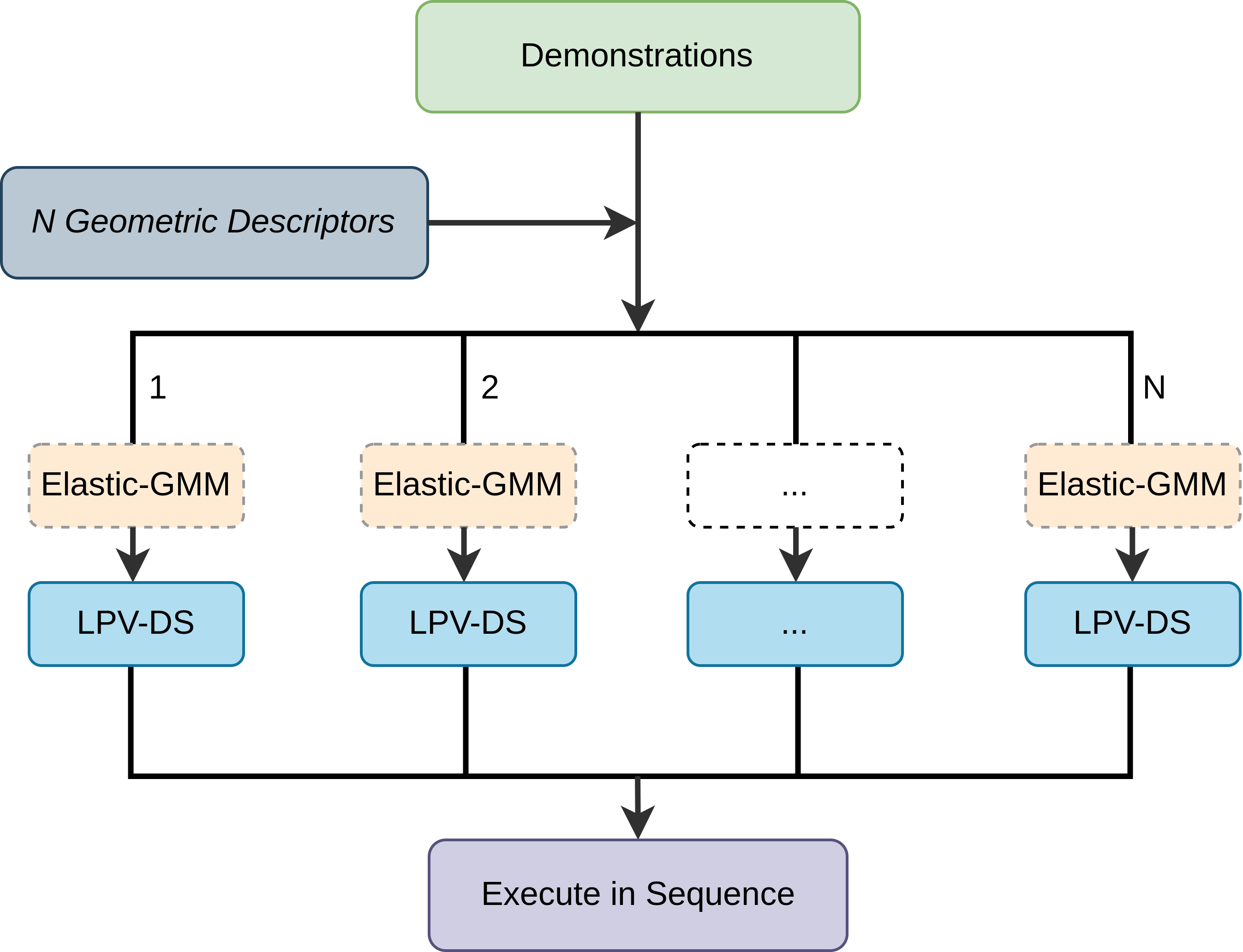
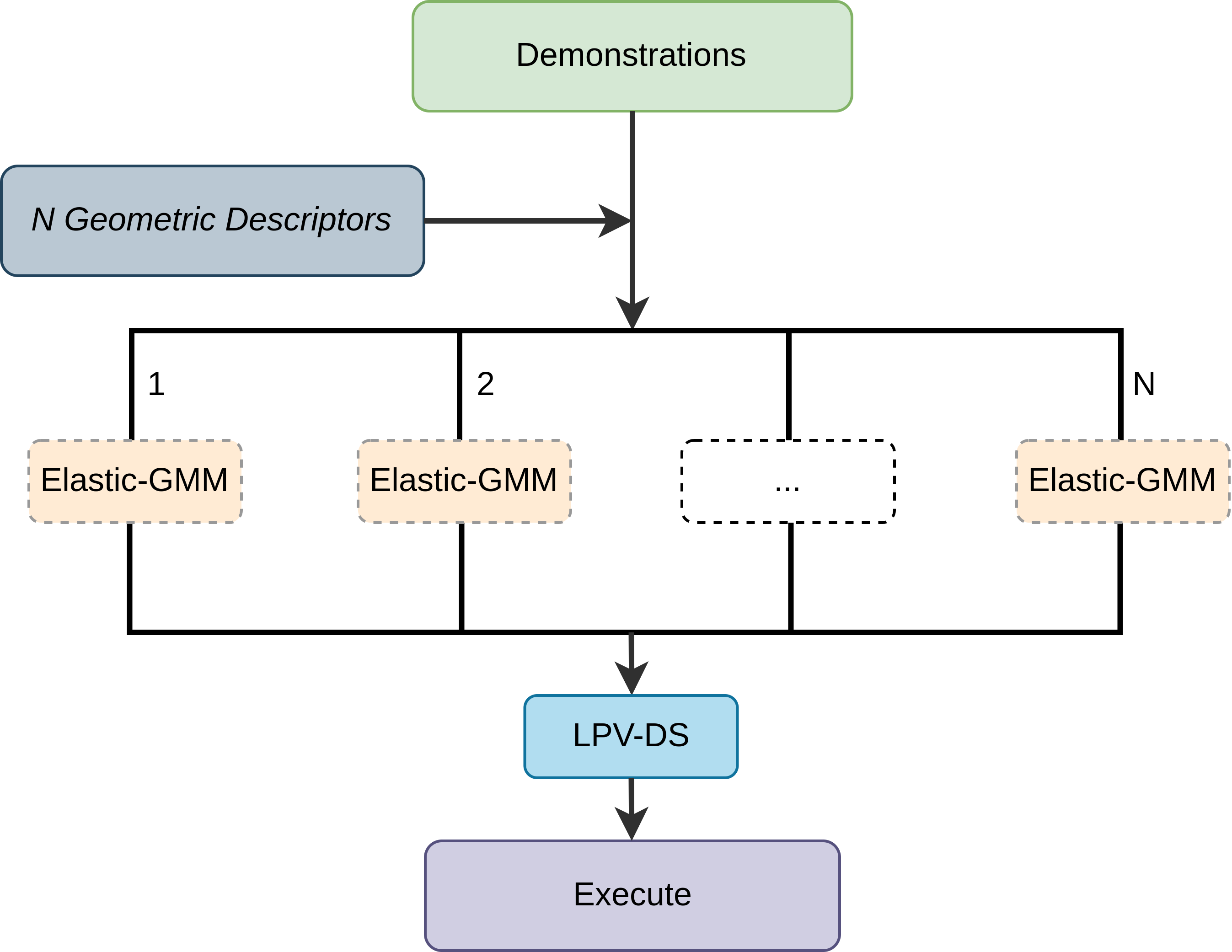
Multiple Elastic-DS could be stitched together to achieve a via-point trajectory and even long-horizon multi-segment tasks. The index in the task parameters represents multiple segments, consequently multiple DSs in (2) when . To allow adding spatial constraints in the middle, one can split the task into multiple segments and process them in a divide-and-conquer manner. There are two possible task-specific cases for stitching the segments: (i) The activation function is in charge of the switch for multiple DSs. The next DS will be activated by when the last DS reaches the attractor. (ii) To create a smooth movement, this case will first connect all the Elastic-GMMs from different segments and then learn a single DS. The function is not in use for this case. As mentioned in Section 2, the interesting separation points described by the geometric descriptors are specified by some upstream sources. For more information about the split and stitching process, please refer to Appendix C. The flexibility of composing and regrouping different transformed DS with the new constraint poses allows the possibility for multi-task scenarios.
5 Experimental Results
5.1 2D Experiments
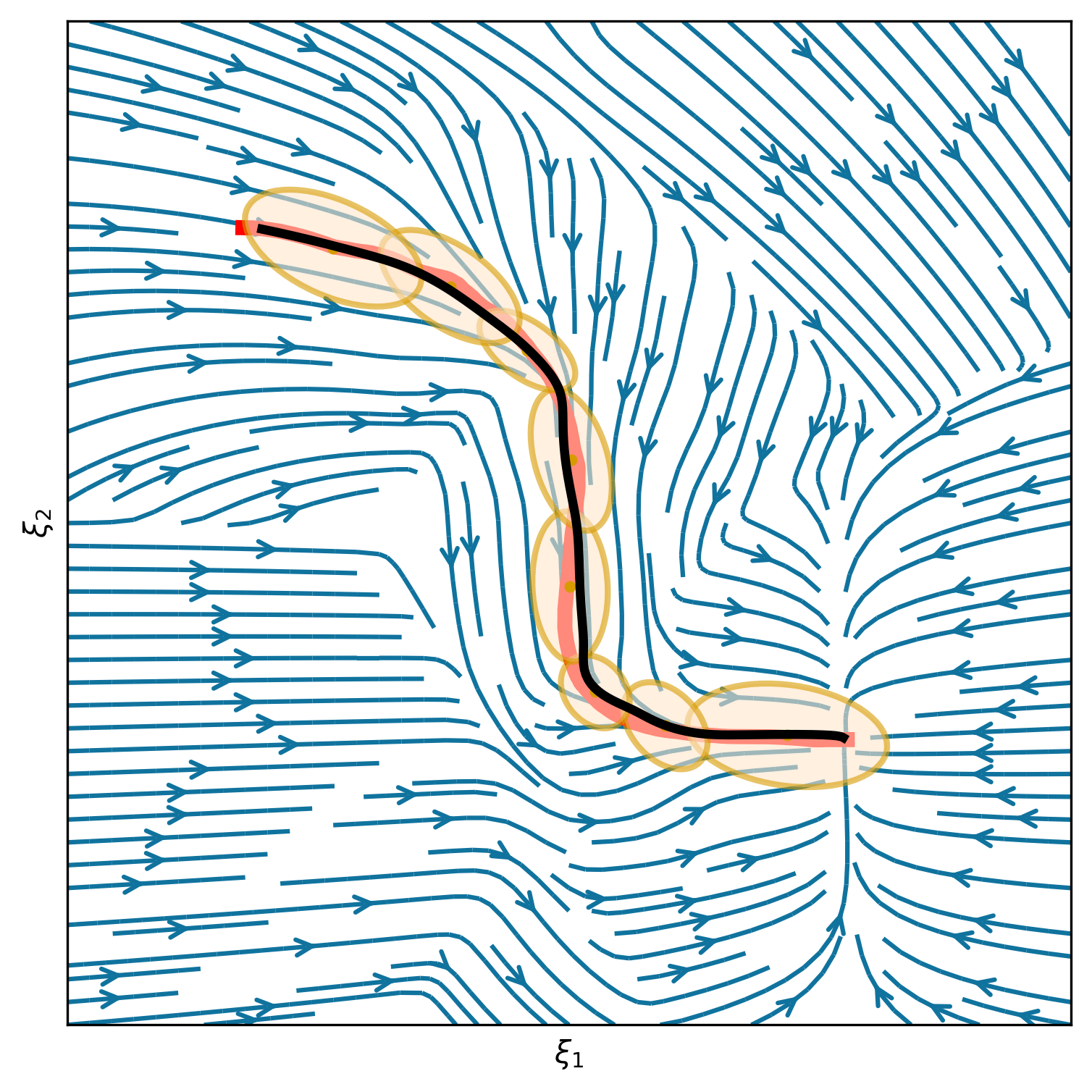
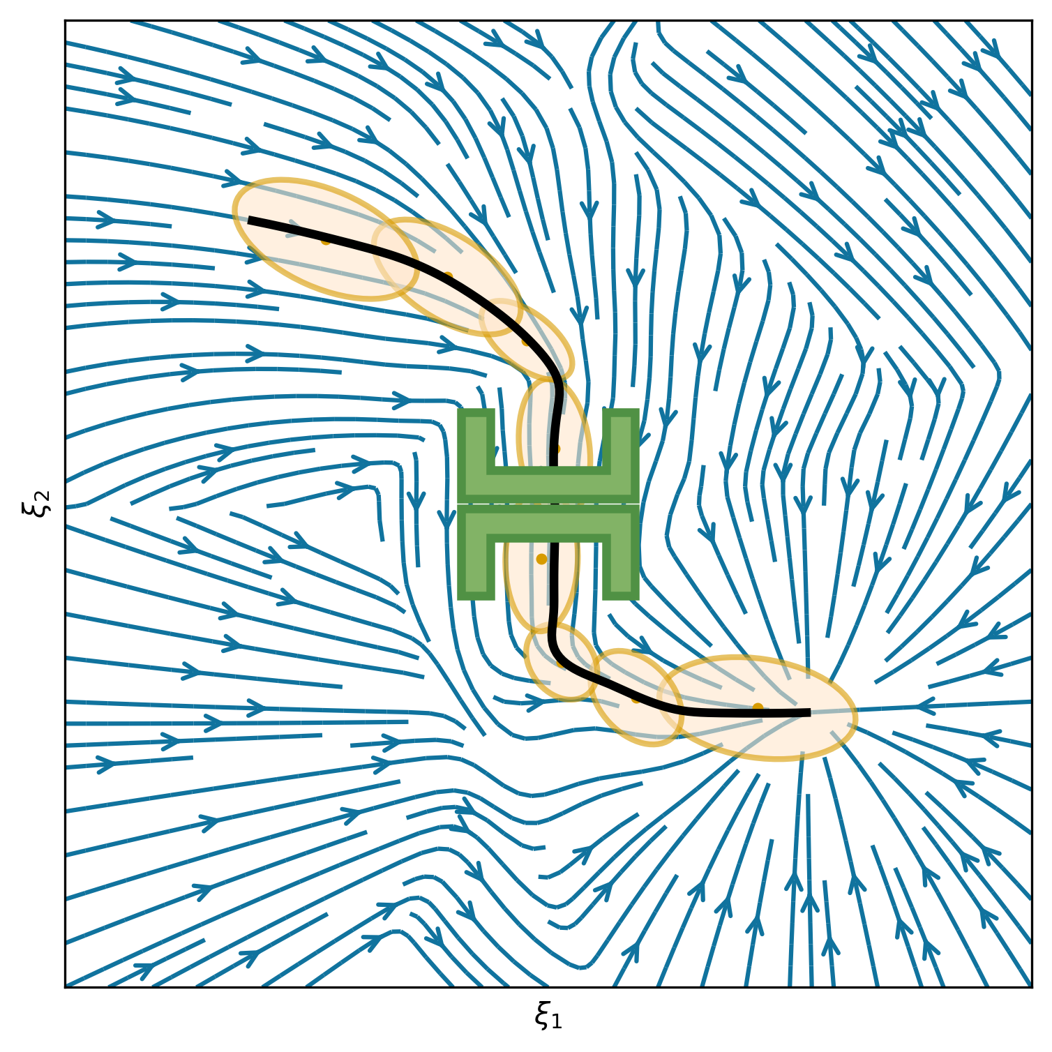
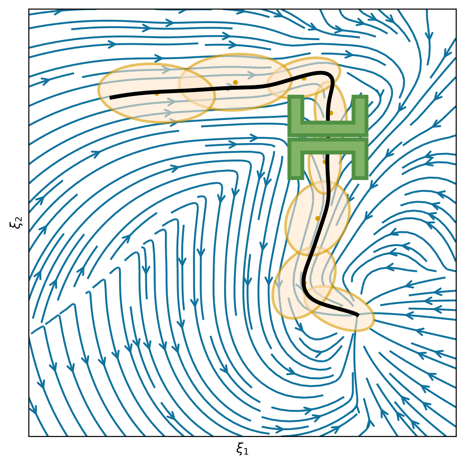
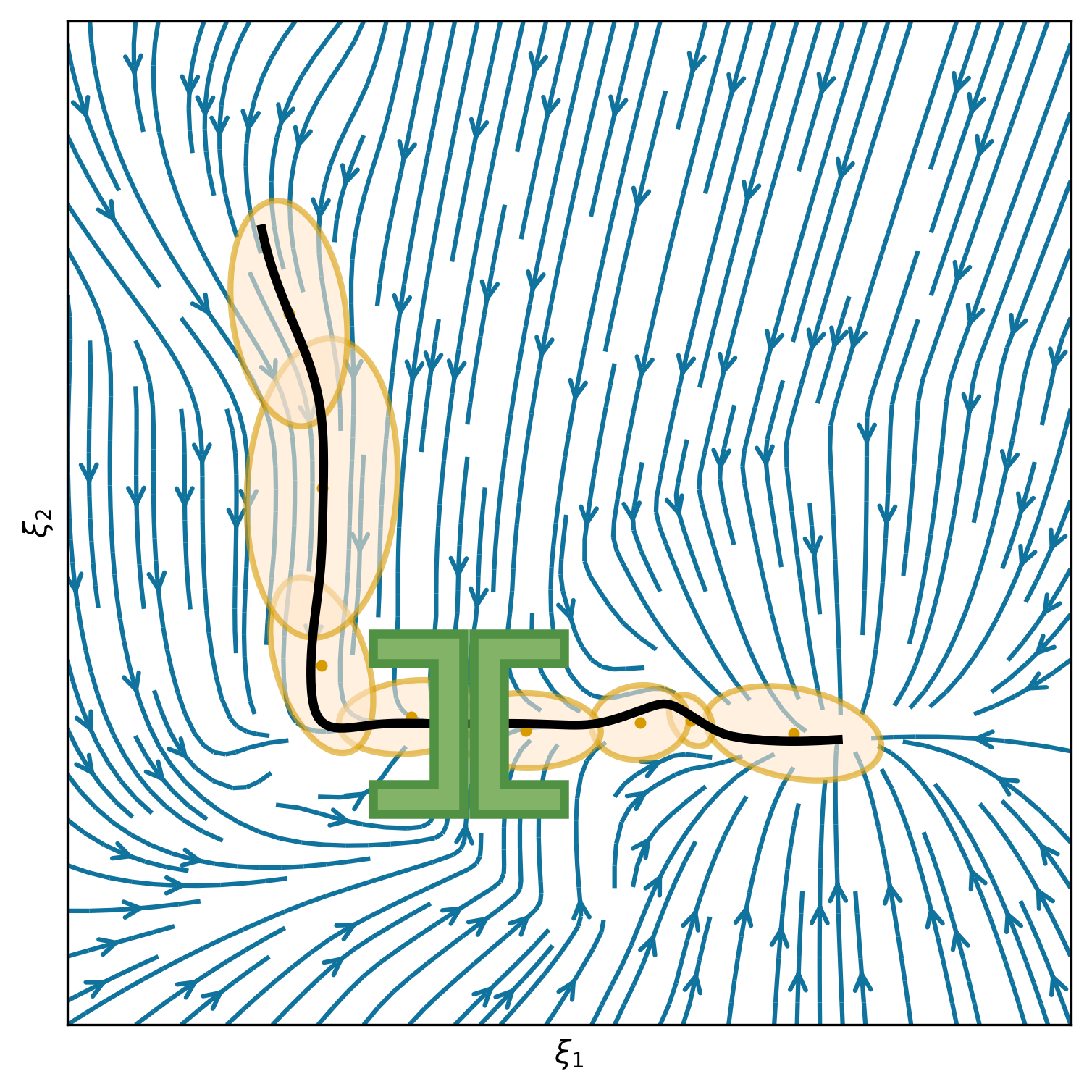
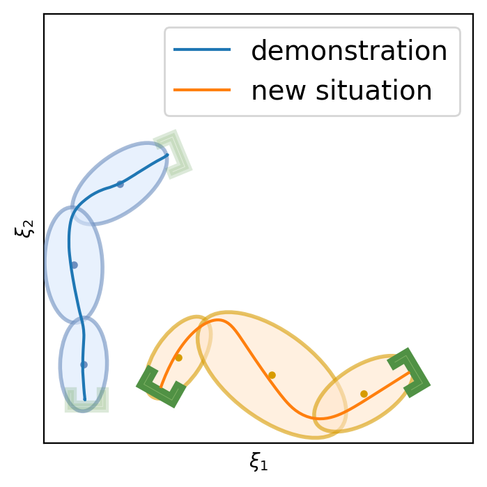
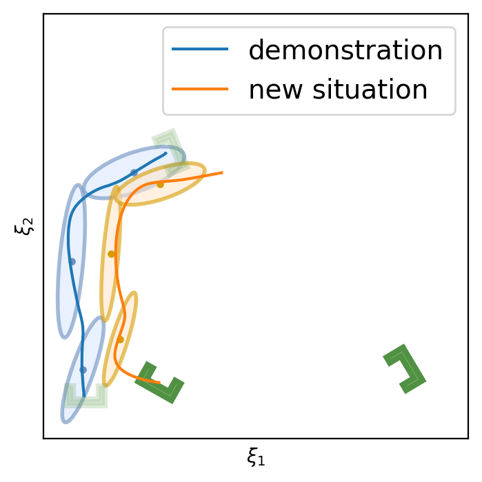
This section shows 2D examples of using Elastic-DS. The learned DS is plotted as steamplots describing a velocity vector field (in blue) with GMM (in orange) geometric descriptors (in green) and rollout trajectory (in black) overlaying on top. The 2D simulation in Figure 5 shows the atomic case of one segment trajectory conditioned on a geometric descriptor with constraints at the endpoints. The two ends of the geometric descriptor (green polygons) are shifted and rotated to show different configurations and the changes in the DS vector field. Figure 6 shows the example of using a via-point to modify the policy in the middle of a single DS corresponding to case (ii) in section 4.3. The DS motion policy is able to adapt to the changes. For more details about stitching the trajectory, please refer to Appendix C. Figure 7 and Table 1 display a comparison to TP-GMM-DS [50, 51], TP-GPR-DS [52], and TP-proMP [52, 40]. Appendix E shows the failure cases of TP-GMM with fewer demonstrations. With a single demonstration, other methods fail to generalize, while Elastic-DS shows a satisfactory performance. For more comparison details, please refer to Appendix F.
| Metric | Elastic-DS (Ours) | TP-GPR-DS | TP-GMM-DS | TP-proMP |
|---|---|---|---|---|
| Start Cosine Similarity | 0.9843 | -0.3981 | 0.9405 | 0.8061 |
| Goal Cosine Similarity | 0.9998 | 0.5453 | 0.6324 | 0.9070 |
| Endpoints Distance | 0.0008 | 0.835 | 0.0764 | 1.102 |
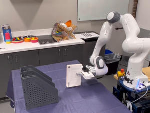
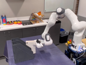
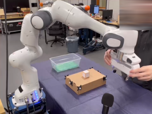
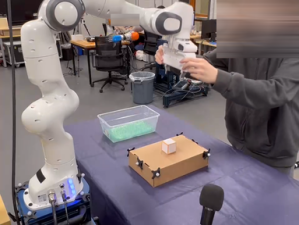
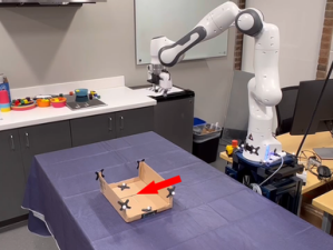
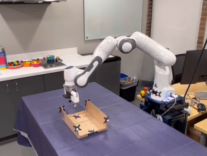
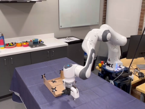
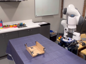
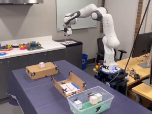
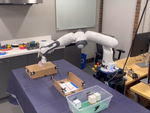
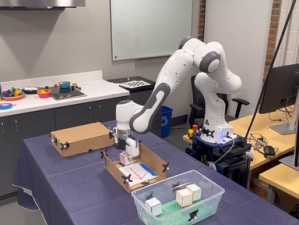
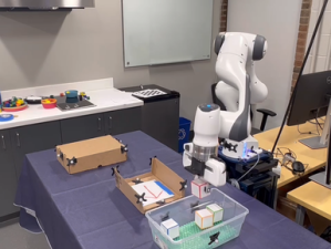
5.2 Robot Experiments
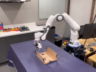
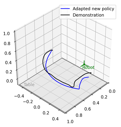
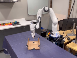
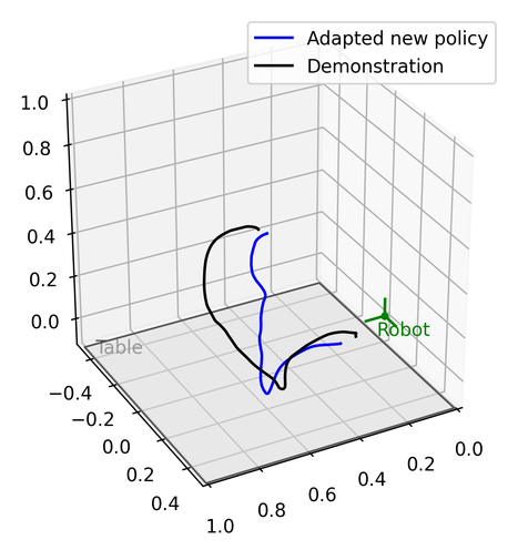
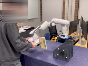
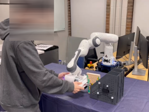
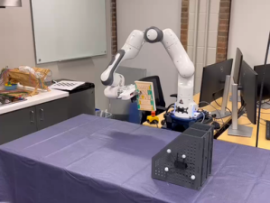
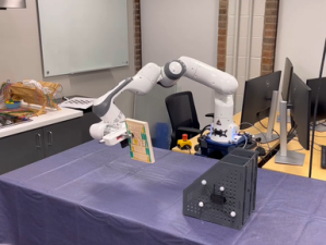
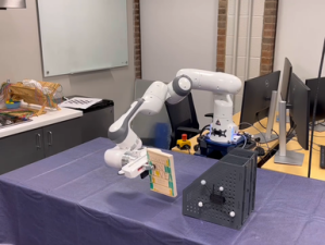
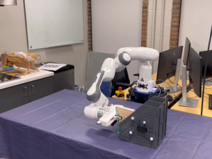
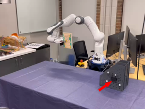
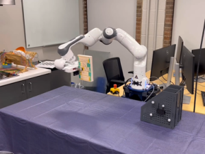
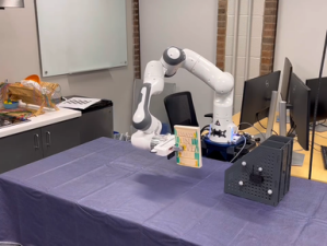
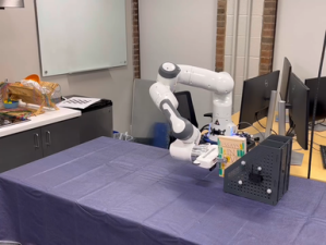
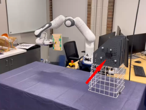
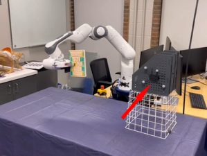
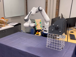
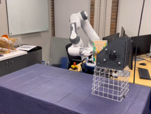
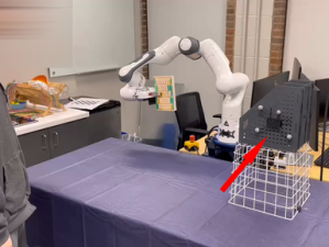
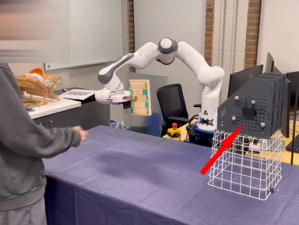
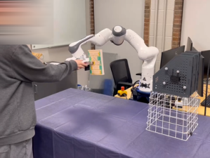
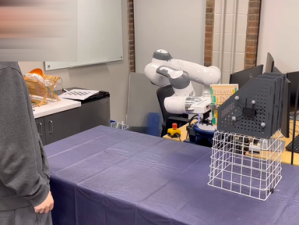
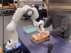
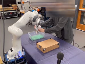
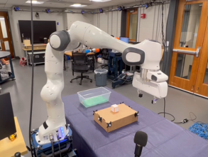
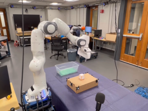
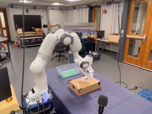
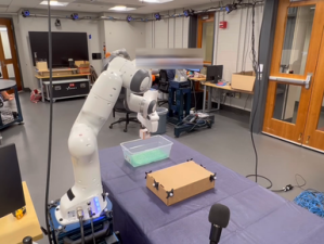
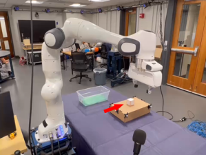
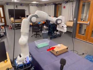
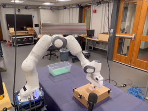
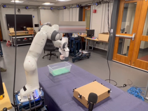
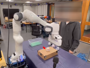
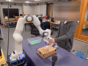
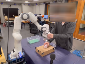
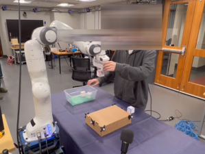
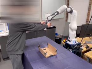
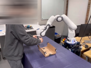
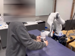
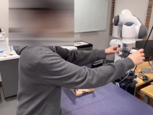
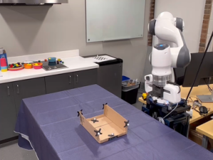
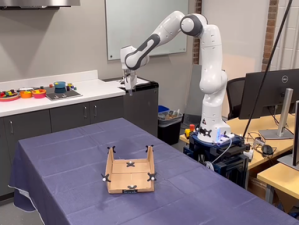
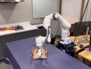
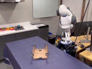
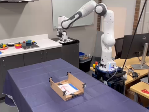
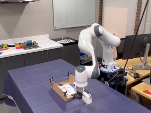
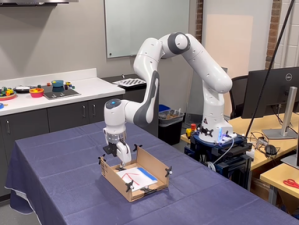
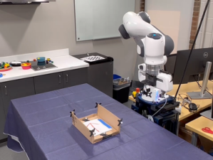
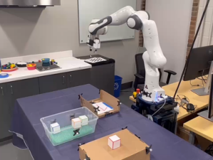
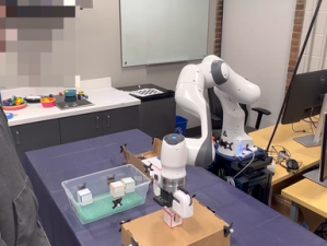
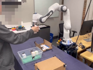
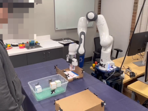
We demonstrate the validation result through four different real robot experiments on the Franka Emika Panda robot: Bookshelf, Pick and Place, Tunnel, and Combination, see Figure 2, 8 and Appendix D. In these experiments, the geometric descriptors are detected from a motion capture system. By attaching motion capture markers on objects, we specify geometric descriptors anchored on the objects of interest. Three experiments will start with a human performing kinesthetic teaching by moving the end-effector. Then, the execution of the original learned DS from the demonstration will be shown. The objects of interest will then be shifted and rotated with different configurations. The last experiment shows the ability to compose new tasks. Without any new demonstration, the robot can still achieve the required tasks. Please refer to the video and Appendix D.
6 Conclusions and Limitations
We propose Elastic-DS in this work, which allows modifying DS with task parameters conditioned on geometric features to achieve task generalization. As the core component, we introduced Elastic-GMM to augment the original LPV-DS to create more flexible task-specific motions with as low as one demonstration. By showing both 2D simulation and different 3D robot experiments, we validate the ability of Elastic-DS to perform task generalization as well as the potential for multi-task and long-horizon motion policies. Following we discussed the limitations of our approach.
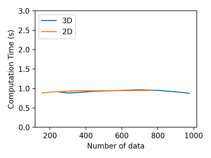
Limitations First, this work only considers end-effector motions in the Cartesian position space. The task constraints are only for translational motion as well. To achieve more variety of tasks and extend to more possible poses, the orientation space has to be considered. Further directions could adopt works like [53] and [54] to produce DS motion policies and meet task constraints in the full pose space. To go even further, the full pose could also contain the gripper state, which could be achieved with a coupled DS approach such as [55] and [3]. Motion policy in the joint space should also be considered [56]. Second, the geometric descriptors are assumed to be given by human specification in this work. To address this limitation, we could utilize object tracking methods like BundleTrack [57] to identify the geometric interactions between the robot demonstration and objects. Finally, the task adaptation in this work is fast yet not real-time ( for 2D and 3D data on a typical laptop with Intel i7-12700H and 16GB memory, depending on the complexity of the task). Computation time analysis is provided in Appendix H. With the dynamic nature of physical human-robot interaction, it is important to provide continuous adaptation on the fly to create a seamless experience. Hence, our immediate next step is to accelerate adaptation time to ms scale.
References
- Lasota et al. [2017] P. A. Lasota, T. Fong, and J. A. Shah. A survey of methods for safe human-robot interaction. Foundations and Trends® in Robotics, 5(4):261–349, 2017. ISSN 1935-8253.
- Sanneman et al. [2021] L. Sanneman, C. Fourie, and J. A. Shah. The state of industrial robotics: Emerging technologies, challenges, and key research directions. Foundations and Trends® in Robotics, 8(3):225–306, 2021. ISSN 1935-8253.
- Billard et al. [2022] A. Billard, S. Mirrazavi, and N. Figueroa. Learning for Adaptive and Reactive Robot Control: A Dynamical Systems Approach. MIT Press, 2022.
- Argall et al. [2009] B. D. Argall, S. Chernova, M. Veloso, and B. Browning. A survey of robot learning from demonstration. Robotics and autonomous systems, 57(5):469–483, 2009.
- Schaal [1996] S. Schaal. Learning from demonstration. Advances in neural information processing systems, 9, 1996.
- Billard et al. [2016] A. G. Billard, S. Calinon, and R. Dillmann. Learning from humans. Springer handbook of robotics, pages 1995–2014, 2016.
- Osa et al. [2018] T. Osa, J. Pajarinen, G. Neumann, J. A. Bagnell, P. Abbeel, J. Peters, et al. An algorithmic perspective on imitation learning. Foundations and Trends® in Robotics, 7(1-2):1–179, 2018.
- Ravichandar et al. [2020] H. Ravichandar, A. S. Polydoros, S. Chernova, and A. Billard. Recent advances in robot learning from demonstration. Annual review of control, robotics, and autonomous systems, 3:297–330, 2020.
- Khansari-Zadeh and Billard [2011] S. M. Khansari-Zadeh and A. Billard. Learning stable nonlinear dynamical systems with gaussian mixture models. IEEE Transactions on Robotics, 27(5):943–957, 2011.
- Ren et al. [2021] A. Ren, S. Veer, and A. Majumdar. Generalization guarantees for imitation learning. In Conference on Robot Learning, pages 1426–1442. PMLR, 2021.
- Ziebart et al. [2008] B. D. Ziebart, A. L. Maas, J. A. Bagnell, A. K. Dey, et al. Maximum entropy inverse reinforcement learning. In Aaai, volume 8, pages 1433–1438. Chicago, IL, USA, 2008.
- Sadigh et al. [2017] D. Sadigh, A. D. Dragan, S. Sastry, and S. A. Seshia. Active preference-based learning of reward functions. 2017.
- Zhao et al. [2022] Z. Zhao, Z. Wang, K. Han, R. Gupta, P. Tiwari, G. Wu, and M. J. Barth. Personalized car following for autonomous driving with inverse reinforcement learning. In 2022 International Conference on Robotics and Automation (ICRA), pages 2891–2897, 2022. doi:10.1109/ICRA46639.2022.9812446.
- Finn et al. [2017] C. Finn, T. Yu, T. Zhang, P. Abbeel, and S. Levine. One-shot visual imitation learning via meta-learning. In Conference on robot learning, pages 357–368. PMLR, 2017.
- Wang et al. [2021] H. Wang, H. Zhao, and B. Li. Bridging multi-task learning and meta-learning: Towards efficient training and effective adaptation. In International Conference on Machine Learning, pages 10991–11002. PMLR, 2021.
- Pan and Yang [2010] S. J. Pan and Q. Yang. A survey on transfer learning. IEEE Transactions on knowledge and data engineering, 22(10):1345–1359, 2010.
- Sun et al. [2022] L. Sun, H. Zhang, W. Xu, and M. Tomizuka. Paco: Parameter-compositional multi-task reinforcement learning. In A. H. Oh, A. Agarwal, D. Belgrave, and K. Cho, editors, Advances in Neural Information Processing Systems, 2022. URL https://openreview.net/forum?id=LYXTPNWJLr.
- Thrun and Mitchell [1995] S. Thrun and T. M. Mitchell. Lifelong robot learning. Robotics and autonomous systems, 15(1-2):25–46, 1995.
- Ruvolo and Eaton [2013] P. Ruvolo and E. Eaton. Ella: An efficient lifelong learning algorithm. In International conference on machine learning, pages 507–515. PMLR, 2013.
- Mendez et al. [2022] J. A. Mendez, H. van Seijen, and E. Eaton. Modular lifelong reinforcement learning via neural composition. arXiv preprint arXiv:2207.00429, 2022.
- Aljundi et al. [2019] R. Aljundi, K. Kelchtermans, and T. Tuytelaars. Task-free continual learning. In Proceedings of the IEEE/CVF Conference on Computer Vision and Pattern Recognition, pages 11254–11263, 2019.
- Figueroa and Billard [2018] N. Figueroa and A. Billard. A physically-consistent bayesian non-parametric mixture model for dynamical system learning. In A. Billard, A. Dragan, J. Peters, and J. Morimoto, editors, Proceedings of The 2nd Conference on Robot Learning, volume 87 of Proceedings of Machine Learning Research, pages 927–946. PMLR, 29–31 Oct 2018. URL https://proceedings.mlr.press/v87/figueroa18a.html.
- Wang et al. [2022] Y. Wang, N. Figueroa, S. Li, A. Shah, and J. Shah. Temporal logic imitation: Learning plan-satisficing motion policies from demonstrations. In 6th Annual Conference on Robot Learning, 2022. URL https://openreview.net/forum?id=ndYsaoyzCWv.
- Bain and Sammut [1995] M. Bain and C. Sammut. A framework for behavioural cloning. In Machine Intelligence 15, pages 103–129, 1995.
- Ross et al. [2011] S. Ross, G. Gordon, and D. Bagnell. A reduction of imitation learning and structured prediction to no-regret online learning. In Proceedings of the fourteenth international conference on artificial intelligence and statistics, pages 627–635. JMLR Workshop and Conference Proceedings, 2011.
- Ho and Ermon [2016] J. Ho and S. Ermon. Generative adversarial imitation learning. Advances in neural information processing systems, 29, 2016.
- Pfrommer et al. [2022] D. Pfrommer, T. T. Zhang, S. Tu, and N. Matni. TaSIL: Taylor series imitation learning. In A. H. Oh, A. Agarwal, D. Belgrave, and K. Cho, editors, Advances in Neural Information Processing Systems, 2022. URL https://openreview.net/forum?id=jqzoJw7xamd.
- Zentner et al. [2022] K. Zentner, U. Puri, Y. Zhang, R. Julian, and G. S. Sukhatme. Efficient multi-task learning via iterated single-task transfer. In 2022 IEEE/RSJ International Conference on Intelligent Robots and Systems (IROS), pages 10141–10146. IEEE, 2022.
- Mudrakarta et al. [2019] P. K. Mudrakarta, M. Sandler, A. Zhmoginov, and A. Howard. K for the price of 1: Parameter-efficient multi-task and transfer learning, 2019.
- Rahmatizadeh et al. [2018] R. Rahmatizadeh, P. Abolghasemi, L. Bölöni, and S. Levine. Vision-based multi-task manipulation for inexpensive robots using end-to-end learning from demonstration. In 2018 IEEE international conference on robotics and automation (ICRA), pages 3758–3765. IEEE, 2018.
- Jang et al. [2022] E. Jang, A. Irpan, M. Khansari, D. Kappler, F. Ebert, C. Lynch, S. Levine, and C. Finn. Bc-z: Zero-shot task generalization with robotic imitation learning, 2022.
- Fu et al. [2022] H. Fu, S. Yu, S. Tiwari, G. Konidaris, and M. Littman. Meta-learning transferable parameterized skills. arXiv preprint arXiv:2206.03597, 2022.
- Calinon [2017] S. Calinon. Robot learning with task-parameterized generative models. In Robotics Research: Volume 2, pages 111–126. Springer, 2017.
- Zhu et al. [2022] J. Zhu, M. Gienger, and J. Kober. Learning task-parameterized skills from few demonstrations. IEEE Robotics and Automation Letters, 7(2):4063–4070, 2022.
- Pervez and Lee [2018] A. Pervez and D. Lee. Learning task-parameterized dynamic movement primitives using mixture of gmms. Intelligent Service Robotics, 11(1):61–78, 2018.
- Ureche et al. [2015] A. L. P. Ureche, K. Umezawa, Y. Nakamura, and A. Billard. Task parameterization using continuous constraints extracted from human demonstrations. IEEE Transactions on Robotics, 31(6):1458–1471, 2015. doi:10.1109/TRO.2015.2495003.
- Figueroa et al. [2016] N. Figueroa, A. L. P. Ureche, and A. Billard. Learning complex sequential tasks from demonstration: A pizza dough rolling case study. In 2016 11th ACM/IEEE International Conference on Human-Robot Interaction (HRI), pages 611–612, 2016. doi:10.1109/HRI.2016.7451881.
- Li and Brock [2022] X. Li and O. Brock. Learning from demonstration based on environmental constraints. IEEE Robotics and Automation Letters, 7(4):10938–10945, 2022.
- Ijspeert et al. [2013] A. J. Ijspeert, J. Nakanishi, H. Hoffmann, P. Pastor, and S. Schaal. Dynamical movement primitives: learning attractor models for motor behaviors. Neural computation, 25(2):328–373, 2013.
- Paraschos et al. [2013] A. Paraschos, C. Daniel, J. R. Peters, and G. Neumann. Probabilistic movement primitives. Advances in neural information processing systems, 26, 2013.
- Freymuth et al. [2022] N. Freymuth, N. Schreiber, P. Becker, A. Taranovic, and G. Neumann. Inferring versatile behavior from demonstrations by matching geometric descriptors. arXiv preprint arXiv:2210.08121, 2022.
- Neumann et al. [2013] K. Neumann, A. Lemme, and J. J. Steil. Neural learning of stable dynamical systems based on data-driven lyapunov candidates. In 2013 IEEE/RSJ International Conference on Intelligent Robots and Systems, pages 1216–1222. IEEE, 2013.
- Pérez-Dattari and Kober [2023] R. Pérez-Dattari and J. Kober. Stable motion primitives via imitation and contrastive learning. arXiv preprint arXiv:2302.10017, 2023.
- Chi et al. [2023] C. Chi, S. Feng, Y. Du, Z. Xu, E. Cousineau, B. Burchfiel, and S. Song. Diffusion policy: Visuomotor policy learning via action diffusion. arXiv preprint arXiv:2303.04137, 2023.
- Rana et al. [2020] M. A. Rana, A. Li, H. Ravichandar, M. Mukadam, S. Chernova, D. Fox, B. Boots, and N. Ratliff. Learning reactive motion policies in multiple task spaces from human demonstrations. In Conference on Robot Learning, pages 1457–1468. PMLR, 2020.
- Quinlan and Khatib [1993] S. Quinlan and O. Khatib. Elastic bands: connecting path planning and control. In [1993] Proceedings IEEE International Conference on Robotics and Automation, pages 802–807 vol.2, 1993. doi:10.1109/ROBOT.1993.291936.
- Nierhoff et al. [2016] T. Nierhoff, S. Hirche, and Y. Nakamura. Spatial adaption of robot trajectories based on laplacian trajectory editing. Autonomous Robots, 40:159–173, 2016.
- Kirillov et al. [2023] A. Kirillov, E. Mintun, N. Ravi, H. Mao, C. Rolland, L. Gustafson, T. Xiao, S. Whitehead, A. C. Berg, W.-Y. Lo, P. Dollár, and R. Girshick. Segment anything. arXiv:2304.02643, 2023.
- Lipman et al. [2005] Y. Lipman, O. Sorkine, M. Alexa, D. Cohen-Or, D. Levin, C. Rössl, and H.-P. Seidel. Laplacian framework for interactive mesh editing. International Journal of Shape Modeling, 11(01):43–61, 2005.
- Calinon et al. [2014] S. Calinon, D. Bruno, and D. G. Caldwell. A task-parameterized probabilistic model with minimal intervention control. In 2014 IEEE International Conference on Robotics and Automation (ICRA), pages 3339–3344. IEEE, 2014.
- Calinon et al. [2012] S. Calinon, Z. Li, T. Alizadeh, N. G. Tsagarakis, and D. G. Caldwell. Statistical dynamical systems for skills acquisition in humanoids. In 2012 12th IEEE-RAS International Conference on Humanoid Robots (Humanoids 2012), pages 323–329. IEEE, 2012.
- Calinon [2016] S. Calinon. A tutorial on task-parameterized movement learning and retrieval. Intelligent service robotics, 9:1–29, 2016.
- Figueroa et al. [2020] N. Figueroa, S. Faraji, M. Koptev, and A. Billard. A dynamical system approach for adaptive grasping, navigation and co-manipulation with humanoid robots. In 2020 IEEE International conference on robotics and automation (ICRA), pages 7676–7682. IEEE, 2020.
- Urain et al. [2022] J. Urain, D. Tateo, and J. Peters. Learning stable vector fields on lie groups. IEEE Robotics and Automation Letters, 7(4):12569–12576, 2022.
- Shukla and Billard [2012] A. Shukla and A. Billard. Coupled dynamical system based arm–hand grasping model for learning fast adaptation strategies. Robotics and Autonomous Systems, 60(3):424–440, 2012.
- Khansari-Zadeh and Khatib [2017] S. M. Khansari-Zadeh and O. Khatib. Learning potential functions from human demonstrations with encapsulated dynamic and compliant behaviors. Autonomous Robots, 41:45–69, 2017.
- Wen and Bekris [2021] B. Wen and K. Bekris. Bundletrack: 6d pose tracking for novel objects without instance or category-level 3d models. In 2021 IEEE/RSJ International Conference on Intelligent Robots and Systems (IROS), pages 8067–8074. IEEE, 2021.
- Kronander and Billard [2016] K. Kronander and A. Billard. Passive interaction control with dynamical systems. IEEE Robotics and Automation Letters, 1(1):106–113, 2016. doi:10.1109/LRA.2015.2509025.
Appendix
Appendix A LPV-DS Parameter Optimization
GMM-based LPV-DS formulation It is described in Section 3 Preliminaries: -GMM and LPV-DS Motion Policy.
|
|
(9) |
DS Estimation The set of DS parameters for is estimated with LPV-DS by minimizing the Mean Square Error (MSE) against the demonstrations [22] subject to stability constraints in Equation 9.
| (10) | ||||
| s. t. |
which is a constrained non-convex semi-definite program (SDP). Further, when is known (or estimated beforehand as in [22]) the problem becomes a convex SDP that can be solved highly efficiently with off-the-shelf QP solvers [22, 3].
Appendix B Creating Velocity Profile with Laplacian Editing
The main goal is to force a linear trajectory to pass through , the Gaussian joints, with Laplacian editing,
| (11) |
We first calculate the total Euclidean distance along the piecewise connected line between neighboring joints with total distance . Then we have the percentage of the progress that the joints positions in make along the total distance . By using , the corresponding is mapped to the index . In practice, by also enforcing constraints between the joints with linearly interpolation will help the trajectory become more aligned with the GMM link and the geometric descriptors. The velocity will be determined by the finite difference between the edited trajectory neighboring data points divided by the collected from the demonstrations. One can specify the velocity by controlling the spacing between the edited trajectory neighboring data points and the number of points .
Appendix C Stitching from Multiple Segments
As mentioned in the main paper, there are two design trade-off approaches for stitching multiple segments. Depending on the task, one can choose either to learn a DS for each Elastic-GMM (Sequential DS) or learn a single DS for the stitched Elastic-GMM (Combined DS). Figure 10a shows the flow describing the former case, and Figure 10b shows the flow for the latter case.
Here is an example of the two cases in which they are used to modify a DS with via-point. By specifying an interesting point in the demonstration (usually by human specification or upstream computer vision method), the trajectory will be split into separate components. Each individual segment will be processed with Elastic-GMM to meet the new interesting via-point geometric constraints as depicted in green polygons. By performing such steps, we can pose constraints not just on the endpoints of the demonstration but also on the intermediate points of the demonstration. This via-point experiment shows that with changes in the via-point constraints, Elastic-DS can adapt to them.
C.1 Sequential Elastic-DS
C.2 Combined Elastic-DS
.
Appendix D Robot Experiments Details
D.1 Software and Hardware Details
For all of these experiments, we used the 7DOF Franka Emika Panda robotic arm controlled via ROS and the libfranka C++ interface. The computer for the experiments ran on Ubuntu 20.04 with Intel i7-11700K 3.6GHz CPU and 32GB memory. To track the geometric descriptors for each task, we use the Optitrack Motion Capture system, which provides us 6DoF frames of the rigid bodies at 100Hz. We first attached a set of motion capture markers to the base of the Franka Panda robot arm, which served as the fixed frame. For each experiment, we attached motion capture markers to the task-relevant objects.
To record demonstrations, we published the robot end-effector position to a ROSbag recording. During the demonstration, the orientation and position of the task-relevant objects will be recorded with the Motion Capture system. We used the finite difference of the collected position data to calculate the trajectory velocity, which forms the training data .
In the training phase, we first use Elastic-GMM implemented in both MATLAB and Python to learn a GMM encoding of the training data. Then, during the testing phase, we use Elastic-GMM implemented in Python to modify the encoded data with the geometric descriptors . The Elastic-GMM output will then become the input to the MATLAB code for learning the motion policy. The execution of the Elastic-DS motion policy is implemented in a C++ ROS node, which takes the current state of the end-effector of the robot as the input. The output of this ROS node is the desired end-effector velocity , which is sent to a low-level cartesian velocity impedance controller implemented in C++ and running at 1kHz. To achieve the required velocity at the end-effector, it performs torque control at the joints. The stiffness parameter of the controller was set to 180.0. The orientation of the end-effector is fixed for every task as the Elastic-DS motion policy is only learned in 3D space.
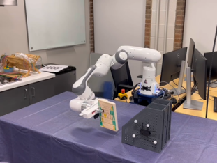
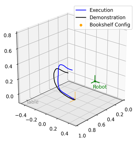
D.2 Bookshelf Experiment
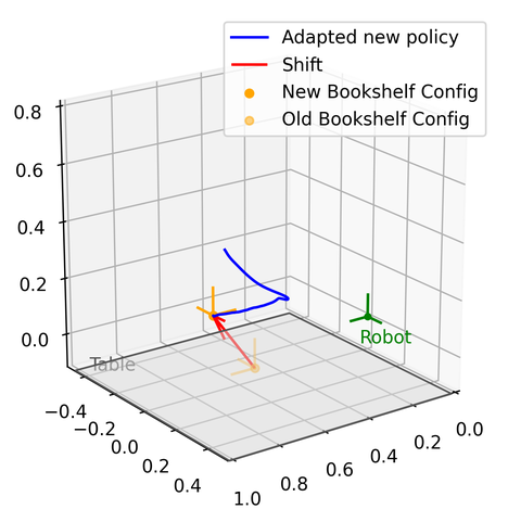
The goal of this experiment is to teach the robot how to insert a book into a desktop bookshelf. With the bookshelf being moved to different locations and orientations on the table, the robot should be able to generalize and reproduce new motion policies for inserting the book into the bookshelf.
Prepare for the experiment:
-
1.
We attached a motion capture marker object to the side of the bookshelf. The goal geometric descriptor was at an offset from the marker object so that it was inside one of the slots in the bookshelf. The orientation of the geometric descriptor was the same as the opening of the bookshelf. Both the position and the orientation were with respect to the fixed frame.
-
2.
Closed the gripper to hold the center of the book vertically.
-
3.
Calibrated the weight of the book so that the robot would not move in gravity compensation.
Collect data:
-
1.
Recorded the robot end-effector position to a ROSbag.
-
2.
At the same moment, the motion capture system recorded the bookshelf (geometric descriptor) position and orientation .
-
3.
As shown in the figure below, a person used hands directly in touch with the robot to perform a kinesthetic teaching demonstration. The ROSbag recording ended as the end effector position reached the bookshelf slot , which is the position in .
-
4.
The single demonstration (end effector position and time-derivative computed numerically with timestamp data ), was then used as the training data . The training data was encoded as Elastic-GMM , as described in Section 4.1. There was no required tuning parameter.
Execution:
-
1.
We moved the robot end-effector (with the book) and the bookshelf to different configurations, as shown in the different figures below and the video. The end-effector orientation with the book was always aligned with the bookshelf opening so that a translational movement could insert the book into the bookshelf.
-
2.
The motion capture system recorded the new configuration of the bookshelf.
-
3.
For the updated bookshelf configuration , we updated the Elastic-GMM to the new situation and learned the Elastic-DS as described in Section 4.1.
-
4.
The robot then executed the DS motion policy in the task space with a velocity-based impedance controller [58].
-
5.
The gripper released the book once it reached the attractor .
-
6.
Repeated with different configurations.
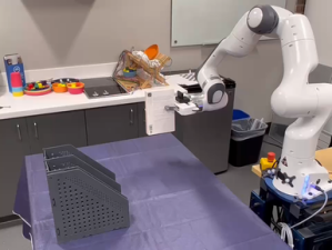
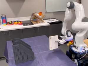
D.3 Pick and Place Experiment
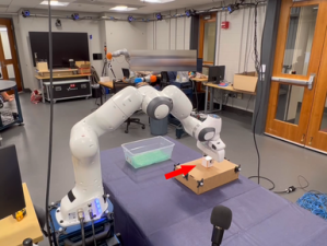
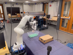
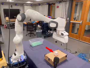
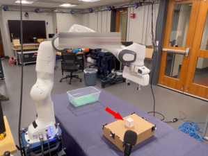
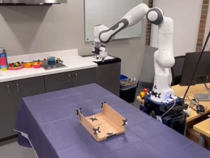
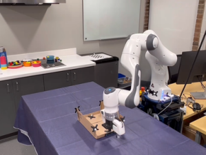
In this task, we will show the robot how to pick and place a cube in a bin. The cube position can be changed (labeled by the motion capture marker on the box as the geometric descriptors while the bin position is fixed). Based on the nature of this task, we manually set two motion segments. However, the cutoff location of the two motion segments is determined automatically by the motion capture data. The first segment is the picking motion with a geometric descriptor at the end of the trajectory (at the cube). The second segment is the placing motion with a geometric descriptor at the beginning to ensure the robot with the cube will move upward first to reach enough height to approach the bin from the top. So there are two geometric descriptors and at the cube to serve as a via-point. During the demonstration, the gripper open/close is done through voice commands (with the microphone at the bottom right of the snapshots). The gripper state is memorized and associated with each segment. At the end of each segment (reaching the attractor), the robot will open/close the gripper depending on commands during the demonstration.
Prepare for the experiment:
-
1.
We attached a motion capture marker set to a base box for placing the cube.
Collect data:
-
1.
Record robot end-effector position to a ROSbag.
-
2.
At the same moment, the motion capture system recorded the box (geometric descriptors ) position and from and . This became the cutoff of the two motion segments. As shown in the figure below, a person used hands directly in touch with the robot to perform a kinesthetic teaching pick and place demonstration in a single trajectory.
-
3.
The human used voice command (with the mic at the bottom of the figures) to control the gripper state (open/close). The ROSbag recorded the gripper state.
-
4.
The single demonstration (end-effector position, timestamp data gripper state) was then separated into two parts and used for training. The two segments of training data were encoded as two Elastic-GMM as described in Section 4.1. There was no required tuning parameter.
Execution:
-
1.
We moved the robot end-effector and the box to different positions, as shown in the different figures below. The gripper always pointed downward at all time.
-
2.
The motion capture system recorded the new positions of the box. It served as the new geometric descriptors’ positions and from and as well as the switch position of the two segments. The first geometric descriptor orientation was always pointing down to make the gripper approach the cube from the top. The second geometric descriptor orientation was always pointing up to allow the gripper to reach enough height before placing the cube in the bin.
-
3.
For the updated box (geometric descriptors) configurations and , we updated the Elastic-GMMs to the new situation and learned the Elastic-DSs for the two segments as described in Section 4.1.
-
4.
The multiple DS motion policies with one-hot activation were executed in order separated by a via-point at the cube, switching of them automatically happens at the via-point as described in Appendix C.1.
-
5.
The gripper released the cube once it reached the attractor in .
D.4 Tunnel Experiment
In this experiment, we will show the robot how to pass through a tunnel, mimicking a scanning/inspection task. Two different motion capture marker objects label the entrance and the exit of the tunnel. Separating by the two markers, there are a total of three segments in this task. It is a task with two via points.
Prepare for the experiment:
-
1.
We attached two motion capture objects to two sides of the tunnel (Each object has three markers).
Collect data:
-
1.
Recorded robot end-effector position to a ROSbag.
-
2.
At the same moment, the motion capture system recorded the entry and exit positions from . They became the two cutoffs of the three motion segments. A person then used hands directly in touch with the robot to perform a kinesthetic teaching tunnel demonstration in a single trajectory.
-
3.
The single demonstration (end-effector position and timestamp data) was separated into three segments for individual training. The three segments of training data were encoded as three Elastic-GMMs as described in Section 4.1. There was no required tuning parameter.
Execution:
-
1.
We moved the robot end-effector and changed the tunnel position and orientation. The gripper always pointed downward.
-
2.
The motion capture system recorded the new positions of the tunnel entry and exit. They served as the new geometric descriptor position in as well as the switch position of the three segments. The first segment had a geometric descriptor at the end (at the tunnel entry). The second segment was within the tunnel, so it had two geometric descriptors and at two ends. The third segment had a geometric descriptor at the beginning (at the tunnel exit). All of the geometric descriptors were predefined to point along the tunnel movement direction. They will change based on the relative position of the entry and exit.
- 3.
-
4.
Execution of the motion policy via the cartesian velocity impedance controller


D.5 Combined Experiment (Tunnel + Pick and Place)
There is no demonstration or training in this task. We reuse the Elastic-GMMs (each as ) learned from the previous experiments to compose new sequences which perform new tasks. We manually defined the sequence of the task with the one-hot encoding activation . However, in the future, we plan to develop high-level planning algorithms to determine the sequence automatically.
Prepare for the experiment:
-
1.
We used all the previous components except for the bookshelf. The motion capture markers were placed in the same way as in the previous experiments. This time, we also added markers to the bin for the cube placing. There were a total of 7 geometric descriptors
-
2.
We defined the sequence of the execution (Pick-Scanning-Place) in . There were a total of four motion segments in this task, corresponds to .
Execution:
-
1.
We moved the robot end-effector and changed the object positions. The gripper always pointed downward.
-
2.
The motion capture system recorded the new positions of the objects. The geometric descriptors were updated.
-
3.
We updated the four Elastic-GMMs to the new geometric descriptors’ configurations based on the motion capture data and learned four Elastic-DSs , as described in Section 4.1.
-
4.
Execution of the Sequential Elastic-DS motion policy (Appendix C.1) via the cartesian velocity impedance controller
Appendix E Failure Cases for TP-GMM Task-Parameterized Learning
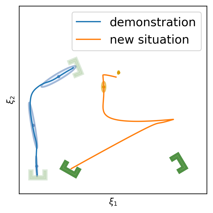
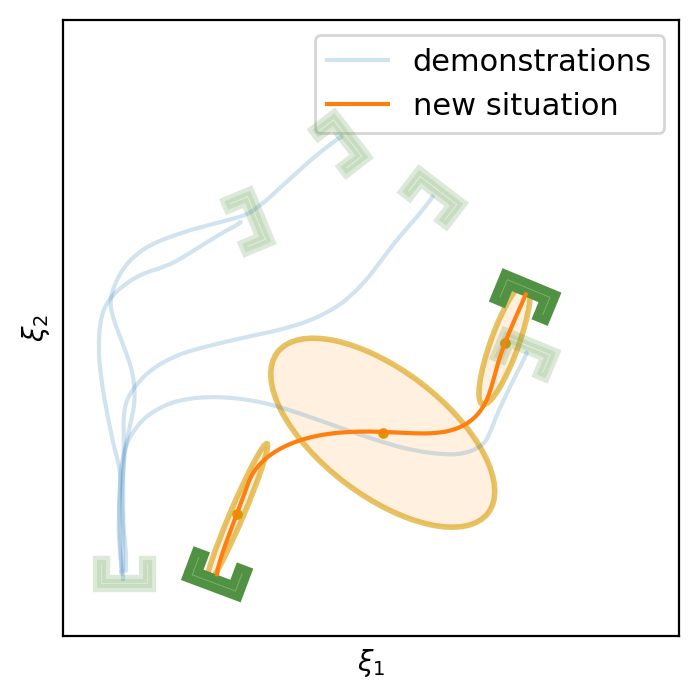
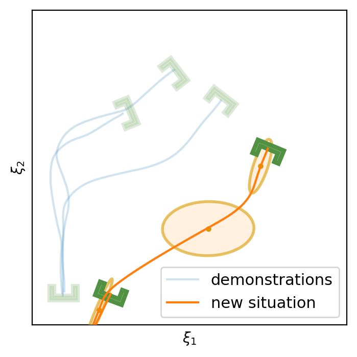
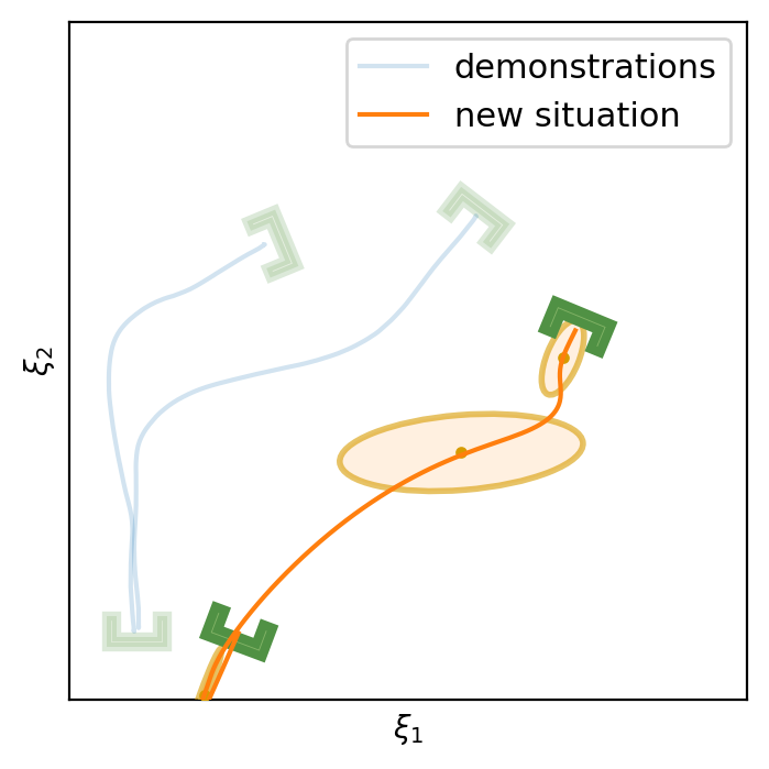
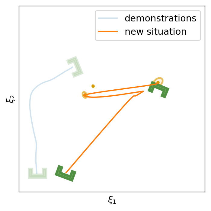
This section shows the performance of task-parametrized policy learning under a different number of demonstrations. Specifically, the method shown here uses Task-Parameterized Gaussian Mixture Model as the encoding strategy and Gaussian mixture regression as the trajectory reproduction [52, 51]. There are two examples in total. Each example will start with four demonstrations (samples) in blue (but faded), moving from the bottom geometric descriptor (frame) to four various other geometric descriptors on top. For the new situation, the two geometric descriptors will be placed at new positions (in deep green). The orange trajectory shows the reproduction in the new situation, with the orange ellipses being the GMM encoding. The number of demonstrations will decrease in each example to show the generalization ability to the new situation with less training data as well as the sensitivity to the coverage of the training data.
E.1 Case Example 1
E.2 Case Example 2
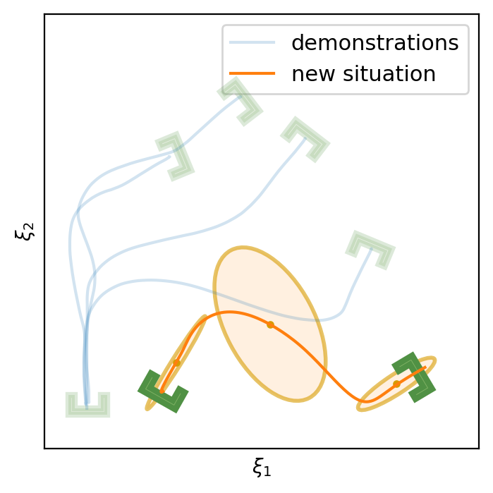
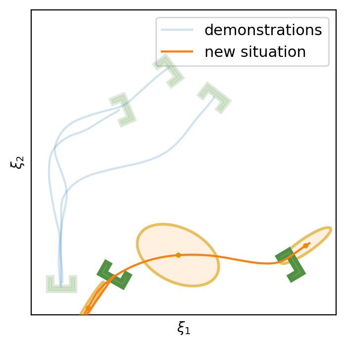
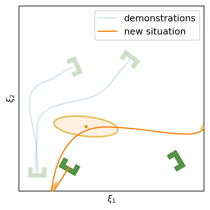
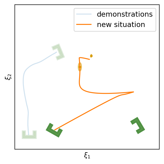
In conclusion, TP-GMM does not generalize well when reducing the number of demonstrations in these two examples. It requires more effort to determine the appropriate placement of the demonstrations to generalize well. With a single demonstration, it tends to overfit that trajectory. The next section will show the performance of Elastic-DS being able to generalize well with a single demonstration compared to other TP approaches.
Appendix F Compare to Existing Methods
To show the advancement of our method, we create both qualitative and quantitative comparisons against various benchmark methods in the task-parametrized (TP) approach [52, 50]. Specifically, the benchmarks include Task-Parameterized Gaussian Process Regression with DS-GMR for motion reproduction (TP-GPR-DS) [52], Task-Parameterized Gaussian Mixture Model with DS-GMR for motion reproduction (TP-GMM-DS) [51, 50, 52], Task-Parameterized Probabilistic Movement Primitives (TP-proMP) [52, 40]. We use different quantitative metrics to show satisfaction in generalizing tasks:
-
•
Start Cosine Similarity: It describes the starting direction of the trajectory and how it aligns with the entry/starting geometric descriptor. We take the first two data points to create a vector and compare it against the pointing direction of the entry/starting geometric descriptor . The closer this value is to one, the better.
(12) -
•
Goal Cosine Similarity: It describes the goal reaching direction of the trajectory and how it aligns with the goal/exit geometric descriptor. We take the last two data points of the trajectory to create a vector and compare it against the pointing direction of the goal/exit geometric descriptor . The closer this value is to one, the better.
(13) -
•
Endpoints Distance: Besides the pointing direction, it is important that the trajectory starts from the center of the starting geometric descriptor and reach the center of the goal geometric descriptor . Let be the start of the trajectory and be the end of the trajectory. The metric will be the sum of the two Euclidean distances. The smaller this value, the better.
(14)
We compare four different trials with the same training data (a single demonstration): Close, Far, Both Ends Shifted, and Both Ends Shifted Far with increasing difficulty levels. Each subsection below describes a trial with a plot showing with red arrows how the geometric descriptors (in green) are being changed. Then it will be followed by four plots showing our method compared to three other methods. Each subsection will include a table showing the quantitative comparison. The single demonstration data is taken from the attached library code in [52]. The parameters for the benchmark methods remain in default as in the code from [52]. There are no required tuning parameters for Elastic-DS.
F.1 Close
| Metric | Elastic-DS (Ours) | TP-GPR-DS | TP-GMM-DS | TP-proMP |
|---|---|---|---|---|
| Start Cosine Similarity | 0.9857 | -0.8222 | 0.9794 | 0.9483 |
| Goal Cosine Similarity | 0.9999 | 0.7397 | 0.5422 | 0.9923 |
| Endpoints Distance | 0.0008 | 0.4298 | 0.7564 | 0.8939 |
F.2 Far
| Metric | Elastic-DS (Ours) | TP-GPR-DS | TP-GMM-DS | TP-proMP |
|---|---|---|---|---|
| Start Cosine Similarity | 0.9971 | -0.9999 | 0.7872 | 0.8987 |
| Goal Cosine Similarity | 0.9997 | 0.5451 | 0.6724 | 0.9675 |
| Endpoints Distance | 0.0009 | 0.8459 | 1.552 | 1.677 |
F.3 Both Ends Shifted
| Metric | Elastic-DS (Ours) | TP-GPR-DS | TP-GMM-DS | TP-proMP |
|---|---|---|---|---|
| Start Cosine Similarity | 0.9843 | -0.3981 | 0.9405 | 0.8061 |
| Goal Cosine Similarity | 0.9998 | 0.5453 | 0.6324 | 0.9070 |
| Endpoints Distance | 0.0008 | 0.835 | 0.0764 | 1.102 |
F.4 Both Ends Shifted Far
| Metric | Elastic-DS (Ours) | TP-GPR-DS | TP-GMM-DS | TP-proMP |
|---|---|---|---|---|
| Start Cosine Similarity | 0.9869 | -0.3827 | 0.8540 | 0.9244 |
| Goal Cosine Similarity | 0.9997 | 0.9378 | 0.7151 | 0.9815 |
| Endpoints Distance | 0.0012 | 1.265 | 1.143 | 1.323 |
Appendix G Transforming Elastic-GMM
Appendix H Training and Adaptation Computation Times
Training and adaptation of the Elastic-DS are performed on a laptop with Intel i7-12700H and 16GB memory. Initial training time for a single demonstration with roughly datapoints is:
-
•
Original PC-GMM implementation in Matlab [22] takes around 2-4 seconds.
-
•
An improved parallelized PC-GMM implementation in C++ takes around 100-200ms.
For parameter adaptation, the recorded computation times are below (considering 3-4 Gaussians):
-
•
Elastic-GMM parameter transfer takes around 30ms-80ms in Python.
-
•
DS parameter learning (SDP optimization) takes around in Matlab.
Hence, for a single demonstrations with datapoints initial training is whereas generating a new policy from task parameter changes takes around 1-2s. The robot experiments presented in this section contain between with . For such datasets the average computation time to generate a new policy is . In Fig. 43 we plot the trend of such computation times as function of increasing .