Targeted Writing and Deleting of Magnetic Skyrmions
in Two-Terminal Nanowire Devices
Abstract
Controllable writing and deleting of nanoscale magnetic skyrmions are key requirements for their use as information carriers for next-generation memory and computing technologies. While several schemes have been proposed, they require complex fabrication techniques or precisely tailored electrical inputs, which limits their long-term scalability. Here we demonstrate an alternative approach for writing and deleting skyrmions using conventional electrical pulses within a simple, two-terminal wire geometry. X-ray microscopy experiments and micromagnetic simulations establish the observed skyrmion creation and annihilation as arising from Joule heating and Oersted field effects of the current pulses, respectively. The unique characteristics of these writing and deleting schemes, such as spatial and temporal selectivity, together with the simplicity of the 2-terminal device architecture, provide a flexible and scalable route to the viable applications of skyrmions.
Introduction
Magnetic skyrmions are spatially localized spin textures with a well-defined topology 1, 2. Their nanoscale size and ambient stability in metallic thin films 3, 4, 5, 6, as well as efficient coupling to electrical currents 7, 8, are desirable inherent attributes that have prompted much excitement 9. Notably, numerous recent device proposals seek to harness the skyrmion motion within a wire geometry 10 to realize applications in memory, logic, and unconventional computing 11, 12, 13. An indispensable requirement for such devices is a spatially and temporally controlled scheme to write and delete skyrmions through robust and scalable techniques.
There has been considerable progress in writing magnetic skyrmions. Theoretical studies suggested that skyrmions can be created by spin currents 14, 15, 16, 17. Recent device-level write efforts have mostly utilized spin-orbit torques (SOTs) in application-relevant materials 9, 18, 19, 17. To facilitate the SOT-writing, the schemes require additional components, for example, geometric constrictions 7, 20, 21, and defects 22, 23. While effective, however, these additional requirements lead to fabrication complexities in some cases, limiting their scalability.
On the contrary, the electrical deletion of skyrmions has thus far been lacking, and has been recognized as a critical pending challenge toward functional skyrmionic devices 22, 23. While two recent schemes have been reported for deterministic deletion and creation of skyrmions 21, 23, they have additional prerequisites, such as in-plane bias field 23 or precisely positioned nanostructures 21. In the other, completely different current paths are required for writing and deletion 21, increasing the complexity of device operation. Therefore, the need for the hour is to realize simple schemes for electrical skyrmion writing and deletion that may be readily adapted to myriad syrmion applications in a controlled fashion.
Here we present a simple and facile approach for writing and deleting skyrmions wherein an identical conventional current pulse is used for both operations. Crucial to this achievement is the harnessing of two by-products of electrical currents: Joule heating and Oersted field. By exploiting contrasting spatial and temporal properties of these two effects, we can achieve targeted operation, e.g., by simply reversing the pulse polarity. The ubiquitous character of these current-induced effects across material systems, coupled with minimalist requirements, offers much-needed attributes of scalability and broad applicability.

This work was performed on multilayer stacks of [Pt(3)/Co(0.9)/MgO(1.5)]15 (Fig. 1a, hereafter Pt/Co/MgO), which were sputtered on X-ray transparent Si3N4 membranes, and fabricated into 2 m wide wires (see Methods). The asymmetric Pt/Co/MgO stack hosts a sizeable interfacial Dzyaloshinskii-Moriya interaction (DMI), which can stabilize Néel-textured skyrmions at room temperature (RT) 4, 24. To observe sub-100 nm magnetic skyrmions in Pt/Co/MgO multilayers, we employed full field magnetic transmission soft x-ray microscopy (MTXM) at the Advanced Light Source (XM-1, BL6.1.2) 25. Out-of-plane (OP) geometry (Fig. 1b) is employed to detect the OP magnetization through X-ray magnetic circular dichroism. The imaging results, acquired at RT with in situ OP magnetic field , are complemented by micromagnetic simulations using magnetic parameters determined from magnetometry measurements (see Methods).
We begin by examining the equilibrium magnetization of the Pt/Co/MgO multilayer, and corresponding MTXM images obtained over a wide wire pad (Fig. 1c). The sheared hysteresis is characteristic of a multi-domain configuration at remanence as confirmed by the labyrinthine zero field (ZF) MTXM image. As is swept down from positive saturation (orange branch in Fig. 1c), stripe domains nucleate at mT, which propagate to form a labyrinthine state. Meanwhile, on the upsweep (green branch in Fig. 1c), increasing beyond zero results in the labyrinthine state transforming to oppositely magnetized stripes, which eventually shrink to a sparse array of sub-100 nm skyrmions. For the subsequent electrical writing experiments, the used magnetic fields correspond to the shaded region of Fig. 1c, wherein the initial MTXM images are uniformly magnetized. Slight discrepancies between device level imaging and film-level results may be attributed to the difference in the numbers of nucleation sites between the patterned wire26 and the film 3.
Electrical Writing of Skyrmions

For electrical writing experiments, we begin by saturating the sample at large positive field, and lower it to a base field ranging from 80 to 126 mT (Fig. 1c, shaded grey region) wherein the sample retains uniform magnetization (Fig. 1d: top). Under these conditions, the injection of a single current pulse (width ns, amplitude A/m2) results in the nucleation of skyrmions in the wire device (Fig. 1d: bottom). We observe that the number of nucleated skyrmions varies considerably with as seen across the MTXM images (Fig. 1d: bottom). The skyrmion nucleation is quantified in Fig. 1e by measuring the density of created skyrmions, , with respect to . Below mT, the current pulse nucleates a dense skyrmion array, with density 5 m-2 (e.g.. left in Fig. 1d). Above 100 mT, drops sharply with increasing (middle in Fig. 1d), and reaches zero at ~120 mT. Notably, the modulation of the electrical nucleation of skyrmions by the external magnetic field is distinct from those reported in previous works 7, 21, 22, 23, 27.
Lateral currents within an asymmetric stack (e.g., Pt/Co/MgO) may produce a large SOT 18. Such SOT governs skyrmion motion and, in some recent works, induces skyrmion nucleation 21, 22, 23. However, the SOT-driven writing mechanisms cannot explain our results for the following reasons. First, our device does not have any geometric constrictions, positioned defects, or in-plane magnetic fields required for the SOT writing of skyrmions 21, 22. Second, unlike the peculiar bipolar pulse waveform used to achieve the dynamic SOT nucleation 23, we use a conventional single pulse with a rectangular profile. Crucially, as we will show in Fig. 3, the same pulse can be used for deletion of skyrmions which clearly rules out vectorial mechanisms associated with SOT. On the other hand, a plausible explanation may be the Joule heating effect and associated thermodynamics, which were previously shown to drive transitions from stripe domains to skyrmions 27. For our case, simulation and analytical modelling suggest that current pulses used may induce a temperature rise 220 K28.
To investigate the plausibility of heat-induced skyrmion nucleation, we performed micromagnetic simulations (see Methods). Typically, such simulations account for temperature effects solely by introducing randomly fluctuating fields 29. However the would additionally change the magnetic parameters. To consider this effect, we measured the saturation magnetization over 300-650 K (Fig. 2a), and estimated the micromagnetic parameters at elevated temperatures using scaling relations with magnetization 30, 31, 32: exchange stiffness , interfacial DMI and uniaxial anisotropy . The micromagnetic simulations were then performed following the recipe depicted in Fig. 2b (details in Supporting Information (SI)). In particular, SOT effects were not included. The system is first initialized to a uniformly magnetized state at (Fig. 2c: top), subjected to a heating phase with rescaled parameters, and then restored to RT conditions (Fig. 2c: bottom).
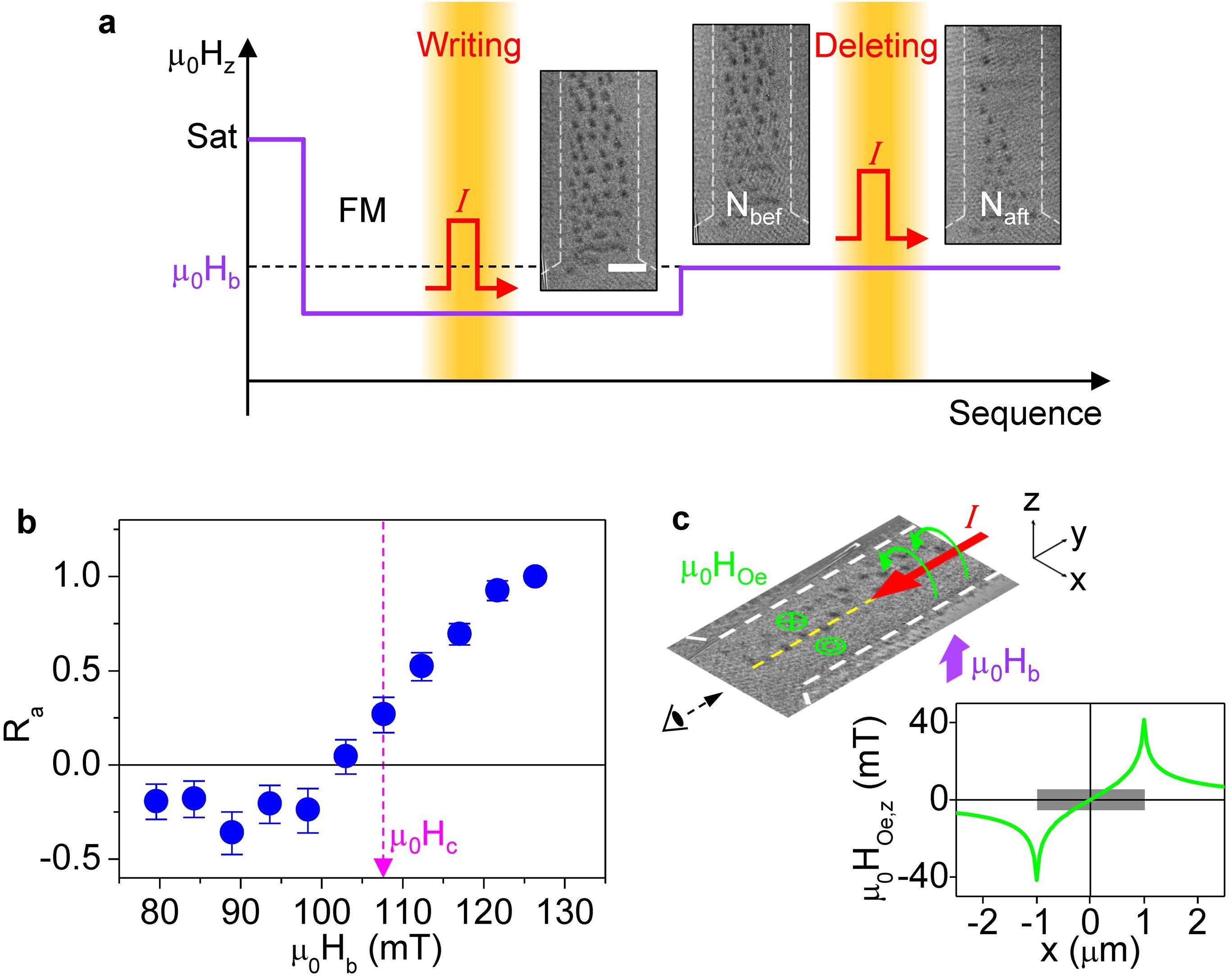
Fig. 2c shows the simulation results for representative values of (111, 165 K) and (90, 120 mT). For = 165 K (Fig. 2c, right), skyrmions are nucleated by the heat pulse, and their number decreases as increases. In contrast, the smaller heat pulse = 111 K (Fig. 2c, left) does not create any skyrmions regardless of . Fig. 2d shows in further detail the simulated with (100-250 K) and (80-120 mT). We find that a threshold 150 K is required to nucleate any skyrmions, corresponding to a scaled magnetization . Above this threshold, the field dependence of is qualitatively consistent with the experimental data (Fig. 1e). Overall, this indicates that Joule heating induced by current pulses is a viable explanation of the observed nucleation of skyrmions and the dependence of on .
Micromagnetic simulations further help to elucidate several aspects of heat-induced skyrmion energetics. First, Fig. 2e shows the energy difference, , between the final and initial (ambient) states with varying and . Notably is negative for most cases, with negligible variation over of 165-228 K, i.e., the skyrmion formation reduces the total energy with respect to that of the uniform state. This indicates that skyrmion nucleation is thermodynamically favoured (explored further in Conclusions), except near saturation ( 120 mT) wherein skyrmions may be metastable. Next, we note a slight qualitative difference in the nucleation phenomenology with (details in SI). For intermediate ( K), skyrmions are formed during the heating phase. However, for higher ( K), i.e., , fluctuations during the heat phase result in random magnetization, and skyrmions are formed only when the heat is turned off. Finally, simulations allow for a sequential study of the two heat-induced effects: thermal fluctuations and rescaling of magnetic parameters. Crucially, we find that no skyrmions are nucleated at any or if magnetic parameters are not rescaled (see SI). Together, these simulation insights strongly point to the thermodynamic origin of the observed nucleation of skyrmions. Finally, while the simulation results in Fig. 2 are grain-free, potential effects of pinning sites on heating and skyrmion nucleation are discussed in the SI.
Electrical Deletion of Magnetic Skyrmions

Meanwhile, we find that a slight modification of the skyrmion nucleation recipe can be used to annihilate skyrmions, as schematically shown in Fig. 3a along with representative MTXM images. Here, the initial state consists of skyrmions created using the writing recipe at = 94 mT (Fig. 3a: left). The magnetic field is then changed to a specific base field (Fig. 3a: centre). The second pulse (deleting) is then injected to the wire, and the numbers of skyrmions before () and after () the current pulse are counted. Here we emphasize that identical current pulses are used for writing and deletion. As shown in Fig. 3a, the number of skyrmions is reduced by following the applied current pulse. Note that the skyrmion annihilation has distint spatial asymmetry: skyrmion annihilation is more prominently on the right side of the wire. We quantify the efficacy of deletion by the annihilation rate . Fig. 3b shows a plot of as a function of . For lower ( mT), maintains a nearly constant negative value, indicating that skyrmions are instead nucleated by the current pulse (see Fig. 1e). Above mT, increases rapidly, consistent with the annihilation of existing skyrmions, and reaches unity near saturation ( mT). The observation that the same current pulse drives nucleation at lower and annihilation at higher suggests the existence of a cross-point field ( mT), corresponding to a dynamic equilibrium between these two phenomena.
The striking spatial asymmetry of skyrmion deletion (Fig. 3a: right), mainly affecting the right side of the wire, is suggestive of an Oersted field driven phenomenon. Notably, reversing the current polarity flips the spatial asymmetry of skyrmion annihilation (SI), further supporting the Oersted field effect. Fig. 3c shows the Oersted field profile during the current pulse, calculated by superposing the fields generated by current segments through the wire cross-section (SI). The Oersted field is sizable (up to mT) compared to (80-130 mT), and introduces considerable spatial asymmetry in the skyrmion distribution by increasing (decreasing) the net perpendicular field on the right (left) of the wire as shown in Fig. 1e and Fig. 3b. Near the cross-point field mT, both nucleation and annihilation are likely equally effective, resulting in the clear spatial segregation of nucleation and annihilation as observed in Fig. 1d and Fig. 3a. Therefore, our scheme has distinctive merits when operating near as one can selectively switch between nucleation and annihilation at a given spatial location simply by reversing the current polarity.
To elucidate the annihilation process, micromagnetic simulations were performed following the recipe depicted in Fig. 4a (details in SI). Notably, while a current generates an instantaneous Oersted field, generating appreciable (c.f. Fig. 2) requires a few tens of nanoseconds 33. Our simulation recipe accounts for this lag by using an Oersted field (profile shown in Fig. 3c) for the entire 30 ns pulse duration, followed by the heating phase introduced after a 10 ns delay. Fig. 4b shows simulation results at several base fields of 110-140 mT, while Fig. 4c displays the resulting annihilation rate with respect to the lateral position (defined in Fig. 4b). Consistent with experiments (Fig. 3b), the simulated with and the deletion is more prominent on the right side of the wire. Meanwhile, we note that identical current pulses used in the skyrmion writing experiments would produce similar Oersted fields. Therefore, we have verified that such an Oersted field does not affect the simulated nucleation results (see SI). The contrasting influence of the Oersted field in the two cases is likely due to differences in initial conditions and the base field magnitude.
Interestingly, the simulations allow us to analyse the annihilation process in stepwise fashion (c.f. Fig. 4a) to disentangle the various effects at play. The crucial finding is that all annihilation events in Fig. 4 occur within the first 10 ns, wherein is assumed to be nearly zero (SI). No additional annihilation is observed at elevated temperatures with or without the Oersted field. In conjunction with the negative in Fig. 2e, this suggests that Oersted field and Joule heating effects have counteracting outcomes in (de)stabilizing skyrmions.

Notably, while thermal fluctuations have also been suggested to induce annihilation of skyrmions 34, for our case, Joule heating induces skyrmion nucleation and prevents annihilation through rescaling of magnetic parameters over a wide temperature range. Therefore, the time delay between the Oersted field and heating effects, introduced to reflect experimental reality, is crucial to enabling skyrmion deletion. Overall, while the inclusion of a more realistic current profile and material granularity may enable better quantitative agreement with experiments, the simulation results shown here establish the key mechanistic insights needed to interpret the skyrmion creation and annihilation observed in our wire devices.
Summary and Outlook
Fig. 5a,b summarizes the energetics of skyrmion nucleation and annihilation via Joule heating and Oersted field effects. First, at lower base fields, the skyrmion state becomes favorable relative to the uniform state, but nucleation is prevented by an energy barrier (Fig. 5a: left). Magnetic parameters at elevated temperatures resulting from Joule heating reduce this barrier, and, incidentally, further lower the skyrmion energy, thereby enabling skyrmion nucleation (Fig. 5a: center, right). The number of skyrmions formed depends on the energy difference of the uniform and skyrmion states, which may be controlled by adjusting the base field. Meanwhile, at higher base fields, the uniform state is comparable in energy with the skyrmion (Fig. 5b: left), and the energy barrier now prevents skyrmion annihilation. However, the addition of an Oersted field pulls up the skyrmion energy, i.e., further destabilizes skyrmions, resulting in their annihilation regions with increased effective field
In summary, we have described our observations of the writing and deleting of skyrmions by lateral currents applied to a two-terminal wire device. A lateral electric current induces two thermodynamic effects: Joule heating and magnetic field. Our work harnesses the distinct spatial and temporal characteristics of these effects to write and delete skyrmions with efficacies that may be tuned by the external bias field. On one hand, Joule heating drives the nucleation of skyrmions, inherently stable at lower fields, by modifying magnetic parameters at elevated temperatures. On the other hand, the Oersted field preceding Joule heating enables annihilation of skyrmions in regions of higher fields. Together, our experiments and simulations provide a detailed energetic picture of these mechanisms that are generalizable to other skyrmion-hosting materials.
Our writing and deleting schemes are uniquely promising from a scalability perspective, considering the simplicity of device design and electrical inputs needed to implement the schemes. Their immense practical value will inspire immediate efforts towards deterministic and field-free skyrmion manipulation in such devices 21, 22, 23. First, while both Joule heating and Oersted field effects may coexist and counteract, one could ensure for either of these to dominate by varying the length and amplitude of the current pulse 21. Next, the requisite of external fields could be realized by appropriate use of magnetostatic effects 35, 36, 37, 38. While these schemes could be used together in skyrmionic racetrack devices 9, 21, each scheme can also be utilized for independently manipulating skyrmions. For example, the spatially selective nature of Oersted field-induced annihilation could be used to realize fabrication-free logic operations 11. Finally, Joule heating presents itself as a promising technique to emulate a skyrmion bath or reservoir, providing a timely experimental platform for recently proposed novel computing architectures 12, 13.
Methods
Micromagnetic Simulations. Simulations were performed using mumax3 software package 29. The effective medium theory was used to examine an equivalent reduced stack while retaining interlayer interactions 8. The magnetic parameters were as follows (effective medium parameters in parenthesis): J/m ( J/m), A/m ( A/m), J/m3 ( J/m3) and J/m2 ( J/m2). These parameters were determined using procedures in previous works 3, 5, 8, and are in line with published results on similar stacks 4.
Joule Heating. Experimental determination of of the wire is challenging due to the low thermal conductivity of the membrane (substrate) and the short duration of the current pulse (30 ns). Therefore, is estimated using analytical model28 with an assumption all charge is flowing the Pt layers, and is found to be K. Correspondingly, micromagnetic simulations were performed at elevated temperatures (up to K) to emulate the effect of heating. The elevated temperatures were reflected in: (a) the fluctuating thermal field in mumax3, and (b) rescaling of magnetic parameters to reflect their values at the elevated temperatures.
Film Deposition and Device Fabrication. Multilayer stacks of Ta(4)/ [Pt(3)/Co(0.9)/MgO(1.5)]15/Ta(4)/Ru(5) (nominal layer thicknesses in nm in parentheses) were deposited on 200 mm Si/SiO2 (20,000) wafers by ultrahigh-vacuum magnetron sputtering at RT using a Timaris™ UHV system (base pressure Torr) manufactured by Singulus Technologies AG. The active stack was repeated 15 times for optimal XMCD contrast, and the film was simultaneously deposited on 200 nm thick X-ray transparent Si3N4 membranes for the MTXM measurement. Nanowire devices for the MTXM measurement were fabricated on the Si3N4 membranes using electron beam lithography (Elionix™ tool), ion-beam etching (Oxford CAIBE™), and Ta(5)/Au(100)/Ru(20) electrode deposition (Bestec Chiron™). Completeness of resist removal was ensured using an Axcelis™ O2 stripping tool.
Magnetization measurements were performed over 300-700 K using the EZ11 vibrating sample magnetometer (VSM) from MicroSense™ using the stacks deposited on the Si/SiO2 substrates.
MTXM Measurements. A full-field magnetic transmission soft x-ray microscope (MTXM; XM-1, BL6.1.2) located at the Advanced Light Source was used to image sub-100 nm magnetic skyrmions in the nanowires. Imaging was performed in out-of-plane geometry at the Co X-ray absorption edge ( eV). A nanosecond pulse generator (Agilent 81150A) was used to apply current pulses to the nanowires.
Acknowledgements. Works at the ALS were supported by U.S. Department of Energy (DE-AC02-05CH11231). S.-G.J. was supported by the National Research Foundation of Korea (NRF, Korea) grant funded by the Korea government (MSIT) (2020R1C1C1006194). M.-Y.I. acknowledges support by Lawrence Berkeley National Laboratory through the Laboratory Directed Research and Development (LDRD) Program. This work in Singapore was supported by the SpOT-LITE programme (Grant Nos. A1818g0042, A18A6b0057), funded by Singapore’s RIE2020 initiatives, and by the Pharos Skyrmion programme (Grant No. 1527400026) funded by A*STAR, Singapore. We also acknowledge the support of the National Supercomputing Centre (NSCC), Singapore for computational resources. K.-S.L. and D.-H.J. were supported by NRF of Korea grant funded MSIT (NRF-2019R1A2C2002996, NRF-2016M3D1A1027831, and NRF-2019K1A3A7A09033400). J.-I.H. was supported by NRF of Korea grant funded MSIT (2020R1A2C2005932).
References
- Nagaosa and Tokura [2013] N. Nagaosa and Y. Tokura, Topological properties and dynamics of magnetic skyrmions, Nature Nanotechnology 8, 899 (2013).
- Soumyanarayanan et al. [2016] A. Soumyanarayanan, N. Reyren, A. Fert, and C. Panagopoulos, Emergent phenomena induced by spin-orbit coupling at surfaces and interfaces, Nature 539, 509 (2016).
- Soumyanarayanan et al. [2017] A. Soumyanarayanan, M. Raju, A. L. G. Oyarce, A. K. C. Tan, M.-Y. Im, A. P. Petrović, P. Ho, K. H. Khoo, M. Tran, C. K. Gan, F. Ernult, and C. Panagopoulos, Tunable room-temperature magnetic skyrmions in Ir/Fe/Co/Pt multilayers, Nature Materials 16, 898 (2017).
- Boulle et al. [2016] O. Boulle, J. Vogel, H. Yang, S. Pizzini, D. d. S. Chaves, A. Locatelli, T. O. Menteş, A. Sala, L. D. Buda-Prejbeanu, O. Klein, M. Belmeguenai, Y. Roussigné, A. Stashkevich, S. M. Chérif, L. Aballe, M. Foerster, M. Chshiev, S. Auffret, I. M. Miron, and G. Gaudin, Room-temperature chiral magnetic skyrmions in ultrathin magnetic nanostructures, Nature Nanotechnology 11, 449 (2016).
- Moreau-Luchaire et al. [2016] C. Moreau-Luchaire, C. Moutafis, N. Reyren, J. Sampaio, C. A. F. Vaz, N. V. Horne, K. Bouzehouane, K. Garcia, C. Deranlot, P. Warnicke, P. Wohlhüter, J.-M. George, M. Weigand, J. Raabe, V. Cros, and A. Fert, Additive interfacial chiral interaction in multilayers for stabilization of small individual skyrmions at room temperature, Nature Nanotechnology 11, 444 (2016).
- Je et al. [2020] S.-G. Je, H.-S. Han, S. K. Kim, S. A. Montoya, W. Chao, I.-S. Hong, E. E. Fullerton, K.-S. Lee, K.-J. Lee, M.-Y. Im, and J.-I. Hong, Direct Demonstration of Topological Stability of Magnetic Skyrmions via Topology Manipulation, ACS Nano 14, 3251 (2020).
- Jiang et al. [2015] W. Jiang, P. Upadhyaya, W. Zhang, G. Yu, M. B. Jungfleisch, F. Y. Fradin, J. E. Pearson, Y. Tserkovnyak, K. L. Wang, O. Heinonen, S. G. E. t. Velthuis, and A. Hoffmann, Blowing magnetic skyrmion bubbles, Science 349, 283 (2015).
- Woo et al. [2016] S. Woo, K. Litzius, B. Krüger, M.-Y. Im, L. Caretta, K. Richter, M. Mann, A. Krone, R. M. Reeve, M. Weigand, P. Agrawal, I. Lemesh, M.-A. Mawass, P. Fischer, M. Kläui, and G. S. D. Beach, Observation of room-temperature magnetic skyrmions and their current-driven dynamics in ultrathin metallic ferromagnets, Nature Materials 15, 501 (2016).
- Fert et al. [2017] A. Fert, N. Reyren, and V. Cros, Magnetic skyrmions: advances in physics and potential applications, Nature Reviews Materials 2, 17031 (2017).
- Parkin et al. [2008] S. S. P. Parkin, M. Hayashi, and L. Thomas, Magnetic Domain-Wall Racetrack Memory, Science 320, 190 (2008).
- Kang et al. [2016] W. Kang, Y. Huang, X. Zhang, Y. Zhou, and W. Zhao, Skyrmion-Electronics: An Overview and Outlook, Proceedings of the IEEE 104, 2040 (2016).
- Pinna et al. [2018] D. Pinna, F. A. Araujo, J.-V. Kim, V. Cros, D. Querlioz, P. Bessiere, J. Droulez, and J. Grollier, Skyrmion Gas Manipulation for Probabilistic Computing, Physical Review Applied 9, 064018 (2018).
- Prychynenko et al. [2018] D. Prychynenko, M. Sitte, K. Litzius, B. Krüger, G. Bourianoff, M. Kläui, J. Sinova, and K. Everschor-Sitte, Magnetic Skyrmion as a Nonlinear Resistive Element: A Potential Building Block for Reservoir Computing, Physical Review Applied 9, 014034 (2018).
- Iwasaki et al. [2013a] J. Iwasaki, M. Mochizuki, and N. Nagaosa, Current-induced skyrmion dynamics in constricted geometries, Nature Nanotechnology 8, 742 (2013a).
- Lin et al. [2013a] S.-Z. Lin, C. Reichhardt, and A. Saxena, Manipulation of skyrmions in nanodisks with a current pulse and skyrmion rectifier, Applied Physics Letters 102, 222405 (2013a).
- Lin et al. [2013b] S.-Z. Lin, C. Reichhardt, C. D. Batista, and A. Saxena, Driven skyrmions and dynamical transitions in chiral magnets, Physical Review Letters 110, 207202 (2013b).
- Sampaio et al. [2013] J. Sampaio, V. Cros, S. Rohart, A. Thiaville, and A. Fert, Nucleation, stability and current-induced motion of isolated magnetic skyrmions in nanostructures, Nature Nanotechnology 8, 839 (2013).
- Miron et al. [2011] I. M. Miron, K. Garello, G. Gaudin, P.-J. Zermatten, M. V. Costache, S. Auffret, S. Bandiera, B. Rodmacq, A. Schuhl, and P. Gambardella, Perpendicular switching of a single ferromagnetic layer induced by in-plane current injection, Nature 476, 189 (2011).
- Iwasaki et al. [2013b] J. Iwasaki, M. Mochizuki, and N. Nagaosa, Universal current-velocity relation of skyrmion motion in chiral magnets, Nature Communications 4, 1463 (2013b).
- Hrabec et al. [2017] A. Hrabec, J. Sampaio, M. Belmeguenai, I. Gross, R. Weil, S. M. Chérif, A. Stashkevich, V. Jacques, A. Thiaville, and S. Rohart, Current-induced skyrmion generation and dynamics in symmetric bilayers, Nature Communications 8, 15765 (2017).
- Finizio et al. [2019] S. Finizio, K. Zeissler, S. Wintz, S. Mayr, T. Weßels, A. J. Huxtable, G. Burnell, C. H. Marrows, and J. Raabe, Deterministic Field-Free Skyrmion Nucleation at a Nanoengineered Injector Device, Nano Letters 19, 7246 (2019).
- Büttner et al. [2017] F. Büttner, I. Lemesh, M. Schneider, B. Pfau, C. M. Günther, P. Hessing, J. Geilhufe, L. Caretta, D. Engel, B. Krüger, J. Viefhaus, S. Eisebitt, and G. S. D. Beach, Field-free deterministic ultrafast creation of magnetic skyrmions by spin–orbit torques, Nature Nanotechnology 12, 1040 (2017).
- Woo et al. [2018] S. Woo, K. M. Song, X. Zhang, M. Ezawa, Y. Zhou, X. Liu, M. Weigand, S. Finizio, J. Raabe, M.-C. Park, K.-Y. Lee, J. W. Choi, B.-C. Min, H. C. Koo, and J. Chang, Deterministic creation and deletion of a single magnetic skyrmion observed by direct time-resolved X-ray microscopy, Nature Electronics 1, 288 (2018).
- Juge et al. [2019] R. Juge, S.-G. Je, D. d. S. Chaves, L. D. Buda-Prejbeanu, J. Peña-Garcia, J. Nath, I. M. Miron, K. G. Rana, L. Aballe, M. Foerster, F. Genuzio, T. O. Mentes, A. Locatelli, F. Maccherozzi, S. S. Dhesi, M. Belmeguenai, Y. Roussigné, S. Auffret, S. Pizzini, G. Gaudin, J. Vogel, and O. Boulle, Current-Driven Skyrmion Dynamics and Drive-Dependent Skyrmion Hall Effect in an Ultrathin Film, Physical Review Applied 12, 044007 (2019).
- Chao et al. [2005] W. Chao, B. D. Harteneck, J. A. Liddle, E. H. Anderson, and D. T. Attwood, Soft X-ray microscopy at a spatial resolution better than 15 nm, Nature 435, 1210 (2005).
- Woo et al. [2017] S. Woo, K. M. Song, H.-S. Han, M.-S. Jung, M.-Y. Im, K.-S. Lee, K. S. Song, P. Fischer, J.-I. Hong, J. W. Choi, B.-C. Min, H. C. Koo, and J. Chang, Spin-orbit torque-driven skyrmion dynamics revealed by time-resolved X-ray microscopy, Nature Communications 8, 15573 (2017).
- Lemesh et al. [2018] I. Lemesh, K. Litzius, M. Böttcher, P. Bassirian, N. Kerber, D. Heinze, J. Zázvorka, F. Büttner, L. Caretta, M. Mann, M. Weigand, S. Finizio, J. Raabe, M. Im, H. Stoll, G. Schütz, B. Dupé, M. Kläui, and G. S. D. Beach, Current‐Induced Skyrmion Generation through Morphological Thermal Transitions in Chiral Ferromagnetic Heterostructures, Advanced Materials 30, 1805461 (2018).
- Fangohr et al. [2011] H. Fangohr, D. S. Chernyshenko, M. Franchin, T. Fischbacher, and G. Meier, Joule heating in nanowires, Physical Review B 84, 054437 (2011).
- Vansteenkiste et al. [2014] A. Vansteenkiste, J. Leliaert, M. Dvornik, M. Helsen, F. Garcia-Sanchez, and B. V. Waeyenberge, The design and verification of MuMax3, AIP Advances 4, 107133 (2014).
- Nembach et al. [2015] H. T. Nembach, J. M. Shaw, M. Weiler, E. Jué, and T. J. Silva, Linear relation between Heisenberg exchange and interfacial Dzyaloshinskii–Moriya interaction in metal films, Nature Physics 11, 825 (2015).
- Moreno et al. [2016] R. Moreno, R. F. L. Evans, S. Khmelevskyi, M. C. Muñoz, R. W. Chantrell, and O. Chubykalo-Fesenko, Temperature-dependent exchange stiffness and domain wall width in Co, Physical Review B 94, 104433 (2016).
- Tomasello et al. [2018] R. Tomasello, K. Y. Guslienko, M. Ricci, A. Giordano, J. Barker, M. Carpentieri, O. Chubykalo-Fesenko, and G. Finocchio, Origin of temperature and field dependence of magnetic skyrmion size in ultrathin nanodots, Physical Review B 97, 060402 (2018).
- Kim et al. [2008] K.-J. Kim, J.-C. Lee, S.-B. Choe, and K.-H. Shin, Joule heating in ferromagnetic nanowires: Prediction and observation, Applied Physics Letters 92, 192509 (2008).
- Legrand et al. [2017] W. Legrand, D. Maccariello, N. Reyren, K. Garcia, C. Moutafis, C. Moreau-Luchaire, S. Collin, K. Bouzehouane, V. Cros, and A. Fert, Room-Temperature Current-Induced Generation and Motion of sub-100 nm Skyrmions, Nano Letters 17, 2703 (2017).
- Zeissler et al. [2017] K. Zeissler, M. Mruczkiewicz, S. Finizio, J. Raabe, P. M. Shepley, A. V. Sadovnikov, S. A. Nikitov, K. Fallon, S. McFadzean, S. McVitie, T. A. Moore, G. Burnell, and C. H. Marrows, Pinning and hysteresis in the field dependent diameter evolution of skyrmions in Pt/Co/Ir superlattice stacks, Scientific Reports 7, 15125 (2017).
- Juge et al. [2018] R. Juge, S.-G. Je, D. d. S. Chaves, S. Pizzini, L. D. Buda-Prejbeanu, L. Aballe, M. Foerster, A. Locatelli, T. O. Menteş, A. Sala, F. Maccherozzi, S. S. Dhesi, S. Auffret, E. Gautier, G. Gaudin, J. Vogel, and O. Boulle, Magnetic skyrmions in confined geometries: Effect of the magnetic field and the disorder, Journal of Magnetism and Magnetic Materials 455, 3 (2018).
- Ho et al. [2019] P. Ho, A. K. Tan, S. Goolaup, A. G. Oyarce, M. Raju, L. Huang, A. Soumyanarayanan, and C. Panagopoulos, Geometrically Tailored Skyrmions at Zero Magnetic Field in Multilayered Nanostructures, Physical Review Applied 11, 024064 (2019).
- Finocchio et al. [2016] G. Finocchio, F. Büttner, R. Tomasello, M. Carpentieri, and M. Kläui, Magnetic skyrmions: from fundamental to applications, Journal of Physics D: Applied Physics 49, 423001 (2016).
Supplementary Information
S1. Simulating Joule Heating Effects

Joule heating recipe. Micromagnetic simulations of skyrmion writing follow the Joule heating simulation recipe shown in Fig. S1a. The system was initialized to at positive saturation (Step A) and lowered to the base field (90 mT for Fig. S1) at 300 K while retaining the uniformly magnetized state, and allowed to equilibrate for 5 ns (Step B). The temperature was then elevated by for 30 ns (Step C), corresponding to the pulse duration. During this time, the micromagnetic parameters, , , , and were rescaled to values corresponding to following scaling relations detailed in the main text. Subsequently, the temperature was reset to 300 K, and the magnetic parameters were restored to their RT values (Step D). The system was then allowed to equilibrate at RT for 15 ns to produce the final state (Step E).
Nucleation threshold. First, while the final state for Fig. S1b ( = 111 K) remains uniformly magnetized, Fig. S1c ( = 165 K) shows nucleated skyrmions. This supports the existence of a threshold value of (between 111-165 K) for skyrmion nucleation via Joule heating. Second, as seen in Fig. S1d, no skyrmions are nucleated when the = 165 K simulations are performed without rescaling magnetic parameters. This suggests that the rescaling of magnetic parameters, which likely lowers the energy barrier, is critical to this skyrmion nucleation mechanism.
Nucleation snapshots. Fig. S1c shows that skyrmions are nucleated at elevated temperatures for = 165 K (Step C). When is removed, the configuration remains largely the same (Step D), and further equilibration affects a small fraction of the textures (Step E). However, this is not the case in Fig. S1e, wherein is increased to 228 K. In this case, large fluctuations at elevated temperatures produce a randomly magnetized configuration (Step C). The removal of may arbitrarily create a few nucleation (Step D), which equilibrate to form skyrmions (Step E). While both Fig. S1c and Fig. S1e produce skyrmion configurations, their distinction is crucial. In case of Fig. S1e parameters, successive current pulses should correspond to drastically different magnetic configurations. In contrast, they may produce only incremental changes for Fig. S1b parameters.
S2. Simulating Oersted Field Effects

Oersted Field Simulation Recipe. Micromagnetic simulations of skyrmion deletion follow the Oersted field effect simulation recipe shown in Fig. S2a. The system is initialized with the skyrmion configuration created in Fig. S1a Step E. The field is raised to , and allowed to equilibrate for 15 ns (Step F). At this point, the application of a current pulse results in an instantaneous Oersted field and a delayed Joule heating effect. These are simulated by applying an Oersted field with profile in Figure 3c for the full current pulse duration and elevating the temperature by [as in Fig. S1a] after the pulse has been applied for 10 ns. This corresponds first to a 10 ns time window with an Oersted field at 300 K (Step G), and then to a 20 ns time window where the Oersted field and elevated temperature are simultaneously in effect (Step H). Subsequently both these effects are turned off as the system is restored to RT (Step I), followed by equilibration for 15 ns to give the final state (Step J).
Annihilation Snapshots. Skyrmion annihilation is seen for both Fig. S2b ( mT) and Fig. S2c ( mT): the final state (J) has fewer skyrmions than the initial state (F). As clarified in the main text, the annihilation is spatially asymmetric: skyrmions are mostly annihilated on the right side of the image. Here, we clarify the annihilation window by examining the magnetization snapshots across the simulated duration. From inspection of Fig. S2b and c, it is evident that the annihilation occurs predominantly in the 10 ns (between F and G) wherein the Oersted field is present at RT. In contrast, the comparison of snapshots after G, wherein the temperature is also elevated, reveal negligible annihilation, albeit with some random motion of skyrmions. Above statement can be more clearly seen in Fig. S2d. we have tracked the number of skyrmions at each step of the skyrmion deletion simulation at different fields. Fig. S2d shows the number of deleted skyrmions during the Oersted field only phase (F-G) and the heating phase (G-H). It is evident that, during the heating phase (G-H), there is no decrease in the number of skyrmions, and the decrease in the number of skyrmions only takes place during the Oersted field phase (F-G). This suggests that Joule heating effects counteract Oersted field deletion by stabilizing skyrmions.

We note that Joule heating may have been associated with skyrmion erasure in some previous works. In our case, through systematic simulations detailed in Fig. S1, we have found that, over a reasonably wide temperature ranges, the rescaling of micromagnetic parameters associated with heating stabilizes existing skyrmions, and in fact prefers to nucleate additional skyrmions. This allowed us to conclude that the Oersted field is the main factor for the skyrmion annihilation in our case. In this light, we conclude that works reporting heat-based erasure of skyrmions may have explored a rather different phase space regime.
Oersted fields & nucleation. As the nucleation and annihilation pulses are identical, their effects, i.e. Joule heating and Oersted field, should appear in both cases. Having considered them in conjunction during annihilation, we now revert to verifying if the introduction of Oersted fields affects nucleation. In particular, we compare the results from the Fig. S1a recipe (no Oersted field) with those from the Fig. S2a recipe (with Oersted field) for a uniformly magnetized initial state with = 165 K (see Fig. S3). Notably we find little difference between the two sets of results shown in Fig. S3b-c in the intermediate or final stages. Both produce skyrmion configurations with similar characteristics. The diminished contribution of Oersted field effect for this case is due to the uniformly magnetized state in the absence of Joule heating effects (before B). This suggests that once skyrmions are created at elevated temperatures (before C), their deletion is prevented by the concomitant role of Joule heating. In summary, this validates the simulation protocol followed in Fig. S1 (and Fig. 2 in the main text).
S3. Pinning Effects on Skyrmion Nucleation

Within multilayer films, we expect that pinning effects may arise from grain boundaries. These should lead to higher resistivity and therefore to greater heating effects for the same current density. However, from the Mayadas–Shatzkes model [Mayadas et al. Phys. Rev. B 1. 1382 (1970)], electron scattering from grain boundaries is only one of the possible resistive mechanisms. In ultrathin layered films ( nm per layer), the dominant mechanism might be interface scattering [Misra et al. J. Appl. Phys. 85, 302 (1999)]. If this is the case, the correlation between pinning and heating effects will be weak. In order to experimentally address this question, one may need to controllably vary the grain size, e.g., by tuning deposition pressure or performing post-annealing, and subsequently measure the residual resistivity ratio (RRR) of the resulting films. Such experiments are beyond the scope of this manuscript, but nevertheless are important directions for follow-up work.

Notwithstanding their contribution to heating, the question of whether pinning effects are indeed occurring is equally relevant. To address this, we have investigated the spatial distribution of skyrmion nucleation probability in our device for both experimental and simulations. Fig. S4 shows the result obtained by overlapping 11 skyrmion nucleation images. There are several darker spots, corresponding to a high skyrmion nucleation probability. This indicates that our nucleation scheme depends on the local variation of material characteristics, such as defects, which could also serve as pining sites. However, at the moment, we cannot confirm whether the high nucleation probability sites correspond to pinning sites, as this would require investigating skyrmion motion and the distribution of the pinning sites.
Meanwhile, to check if pinning effect could play a role in skyrmion nucleation, we have performed additional simulations with the introduction of random grains. We have compared the results from two sets of simulations (repeated 8 times) with and without grains respectively. For the latter case, the uniaxial anisotropy and interfacial DMI are varied by while all other magnetic parameters remain the same across grains with average size nm. Fig. S5 shows the overlaid distributions of nucleated skyrmions obtained at the final relaxed stage E in Fig. S5a without grains (b) and with grains (c). It is apparent that, with the introduction of grains, skyrmion nucleation occurs more frequently in specific grains, and the skyrmions are pinned at the edges of the grains (d). This result probably explains the several darkest spots in Fig. S4, reflecting the presence of grains strongly affects the nucleation positions of skyrmions.
S4. Skyrmion Size Analysis

We performed analysis on the images in manuscript Fig. 1d for the nucleated skyrmion size (Fig. S6a). Different from the decreasing trend of the skyrmion size with increasing field, the data does not show a decrease in the skyrmion size with the magnetic field.
We to note that the X-ray images in manuscript Fig. 1d are not optimized to precisely determine skyrmion sizes, even though the data quality is sufficient to determine the presence of skyrmions. We further caution that the interpretation of size trends is constrained by limited nucleation statistics at higher fields (10 times lower, see Fig. S6a top). In summary, the nucleated skyrmion images does not have sufficient statistical significance to make meaningful claims about skyrmion size trends with magnetic field.
However, to clarify the evolution of skyrmion size with magnetic field, we performed additional experiments with optimized microscopy conditions. The results in Fig. S6b show a pronounced decrease in skyrmion size with increasing magnetic fields in line with the simulation result in manuscript Fig. 2c.
Please note that, in this additional experiment, initial skyrmions were nucleated at the low field, and we tracked their size as increasing the field. This quasi-static experimental protocol is different from the experiments shown in manuscript Fig. 1d where skyrmions are distinctly nucleated at each measured field. Therefore, we cannot completely exclude the possibility that the sizes of the skyrmions from the two cases cannot be matched. Notably, one could have an inconsistency in skyrmion sizes if only bigger skyrmions survive the current pulse induced thermal fluctuations once nucleated at higher field. However, in the quasi-static case, small skyrmions may also survive in higher fields because there are no significant thermal fluctuations. The effect of pinning could also influence the two cases in different ways.
S5. Calculation of the Oersted Field

The Oersted field in the manuscript was calculated by superposing the magnetic fields generated from wire segments (1 nm2 cross-section) through the wire cross-section (2 m 58 nm). Uniform current density was assumed and the Biot-Savart Law was used. The wire segments of 1 nm cell were chosen because the cell-size dependence of calculated magnetic field profile disappears as the cell-size gets below 10 nm as shown in Fig. S7a. To test the validity of our code, the calculated magnetic field profile is compared with the result of the well-known equation , the magnetic field from a straight line (Ampère’s circuital law), as shown in Fig. S7b. It shows perfect agreement with the equation outside of the wire ( m), confirming that our code for the Oersted field calculation is correct.
S6. Skyrmion Annihilation for Reversed Field and Current

To check if the spatial asymmetry of the skyrmion distribution in the annihilation experiment indeed originates from the Oersted field, we performed skyrmion annihilation experiments with reversed current pulse. The result is displayed in Fig. S8b and is obtained from a different wire but on the same film. The images in Fig. S8a are taken from manuscript Fig. 3a for comparison. It is evident that the skyrmion annihilation is dominant on the left side of the wire for the negative pules (Fig. S8b) while the annihilation is dominant on the right side of the wire for the positive current pules (Fig. S8a). These results are in perfect agreement with the presence Oersted field, confirming the Oersted field effect.