Subsystem surface and compass code sensitivities to non-identical infidelity distributions on heavy-hex lattice
Abstract
Logical qubits encoded into a quantum code exhibit improved error rates when the physical error rates are sufficiently low, below the pseudothreshold. Logical error rates and pseudothresholds can be estimated for specific circuits and noise models, and these estimates provide approximate goals for qubit performance. However, estimates often assume uniform error rates, while real devices have static and/or dynamic distributions of non-identical error rates and may exhibit outliers. These distributions make it more challenging to evaluate, compare, and rank the expected performance of quantum processors. We numerically investigate how the logical error rate depends on parameters of the noise distribution for the subsystem surface code and the compass code on a subdivided hexagonal lattice. Three notable observations are found: (1) the average logical error rate depends on the average of the physical qubit infidelity distribution without sensitivity to higher moments (e.g., variance or outliers) for a wide parameter range; (2) the logical error rate saturates as errors increase at one or a few ’bad’ locations; and (3) a decoder that is aware of location specific error rates modestly improves the logical error rate. We discuss the implications of these results in the context of several different practical sources of outliers and non-uniform qubit error rates.
I Introduction
Quantum computing promises computational speed up in numerous special purpose applications Reiher et al. ; Childs et al. ; Bravyi et al. . An outstanding challenge is that noisy physical operations limit the depth of reliable quantum circuits. Quantum error correction (QEC) provides a fault-tolerant approach to construct deep, reliable circuits and is believed to be an essential tool for scaling Dennis et al. ; Fowler et al. ; Bravyi et al. .
A wide range of qubit gate infidelity distributions are observed in practical devices iOlius et al. ; Hertzberg et al. . A general concern is how a distribution affects logical qubit performance. More specifically, predicting relative performance of sets of qubits with different infidelity distributions is of practical importance for steps like screening selection and acceptance criteria (e.g., quantifying yield and predicting whether outlier infidelities will be tolerable). In this context the qubit set would be an appropriately connected set to implement a quantum error correction code and for which the infidelity distribution was obtained directly or estimated by indirect means Zhang et al. (2022). Recent work has begun to address independent and non-independent, non-identically distributed noise Hanks et al. ; iOlius et al. ; Clader et al. ; Berke et al. , as well as the existence of thresholds in the presence of inoperable qubits and gates Strikis et al. (2023); Nagayama et al. ; Fowler and Gidney ; Auger .
To provide insight about how logical error rates depend on changing parameters of different distributions of physical qubit error rates, we numerically simulate the sensitivity of logical error rates to changes in parameters of several important types of non-identical independent distributed noise. Here we define sensitivity as the change in logical error to any change in a parameter of a noise distribution. The numerics show trends that provide qualitative guidance about how to rank sets of qubits intended for QEC codes such as surface code. Ranking of sets of qubits with non-uniform gate infidelity distributions is in the context of predicting a relative ordering of logical error rates for the different sets of qubits (e.g., predicting which part of a chip will perform a small code better). In the context of providing practical guidance, we choose to examine circuit-level simulations of surface codes and compass codes Li et al. (2019) mapped to the heavy hex latticeChamberland et al. (2020). The heavy hex lattice is chosen, in part, because of its immediate utility in presently available devices sundaresan_matching_2022. To provide additional experimental context, we discuss the relationship of these non-identical error distributions to forms of decoherence such as energy relaxation in superconducting qubits, , which are known to introduce both spatial and temporal infidelity distributions, Fig. 1 (a) Klimov et al. ; Carroll et al. .


We begin with a discussion of the error correction codes used in this work. This includes the first presentation of a rotated subsystem code mapping to the heavy hex lattice and an improved schedule for the heavy hex code Chamberland et al. (2020), section II. We then introduce the different error rate distribution cases used in this work, section III. Key results are highlighted for each of the cases in section IV, while supporting details are placed in supporting appendices. We provide some perspective on the meaning of these results for areas such as pseudothresholds, screening and modularity in the discussion, section V followed by a brief conclusion.
II Quantum error correction on a heavy hexagonal layout
Control and fabrication constraints can impact the yield of large quantum computing devices based on fixed-frequency transmon qubits Hertzberg et al. . This has led to devices with reduced qubit connectivity, using so-called “heavy” (or subdivided) lattices where qubits are placed on vertices and edges of a low-degree planar graph (see Fig. 1b). The lattice’s reduced degree of connectivity eases physical implementation Hertzberg et al. ; Zhang et al. (2022).
There is interest to design fault-tolerant operations adapted to these constraints. For example, Chamberland et al. proposed flag error correction circuits for surface codes and compass codes on heavy lattices Chamberland et al. (2020). Here we consider two codes adapted specifically to the heavy hexagonal lattice, a compass code called the heavy hexagon code (HHC) Chamberland et al. (2020) and the subsystem surface code (SSC) Bravyi et al. (2013).


II.1 Heavy hexagon code (HHC)
The heavy hexagon code is a subsystem stabilizer code Poulin (2005) defined by the gauge group
| (1) | ||||
where , , and is odd for the second term, as shown in Fig. 2a. We choose odd distances throughout this paper. The corresponding stabilizer group, illustrated in Fig. 2b, is
| (2) | ||||
with even for the first term. The X stabilizers are the same as the surface code whereas the Z stabilizers are those of the Bacon-Shor code. This code has a threshold of on the heavy hexagonal lattice for errors detected by the surface code stabilizers, and although there is no corresponding threshold for the Bacon-Shor code stabilizers, low logical error rates can still be achieved Chamberland et al. (2020). Quantum error correction has been experimentally demonstrated on the HHC Sundaresan et al. (2023).
In this work, we apply the idea of schedule-induced gauge-fixing Higgott and Breuckmann (2021) to optimize the total logical error probability of the HHC. This is a general idea that can be applied to CSS subsystem codes wherein gauge operators with deterministic eigenvalues are treated as stabilizers during syndrome processing. For the HHC, the circuits for each gauge operator measurement round are identical to Sundaresan et al. (2023), but the schedule may now repeat the same set of gauge operator measurements multiple times (see Appendix C for details). The decoding algorithm is also identical to the matching decoder in Sundaresan et al. (2023), but detection events are defined with respect to the instantaneous stabilizer groups as described in Higgott and Breuckmann (2021).
II.2 Rotated subsystem surface code (RSSC)
The subsystem surface code (SSC) Bravyi et al. (2013) and the standard surface code are related to each other by a local, constant depth stabilizer circuit. However, the gauge operators of the SSC have weight-3 or less and therefore can be measured by circuits that are naturally fault-tolerant. Higgott and Breuckmann have shown that subsystem surface codes can have high thresholds of under circuit model depolarizing noise Higgott and Breuckmann (2021), which exceeds the threshold of the surface code.
We focus on a rotated form of the SSC Brown et al. (2019) that is defined by the gauge group
| (3) | ||||
| (4) | ||||
| (5) | ||||
| (6) |
where , , and is odd for the weight-3 operators, as shown in Fig. 2c. The index refers to the qubit in the center of the face with corners , , , , where is odd. A distance code has weight-2 X (Z) gauge operators and weight-3 X (Z) gauge operators. We use odd distances throughout the paper. The corresponding stabilizer group is
| (7) | ||||
| (8) |
where with is even. The operators , , , and are defined to be identity whenever . Example stabilizers, which are hexagonal in the bulk, are drawn in Fig. 2d. Since each pair of X and Z stabilizers that overlaps on four qubits has an associated pair of independent, anticommuting gauge operators, an RSSC with odd minimum distance encodes one logical qubit and gauge qubits into data qubits.
The RSSC is a promising option for implementing fault-tolerant quantum computing on a heavy hexagonal lattice for several reasons. First, the gauge operators can be measured by simple circuits. Second, the RSSC has a threshold, so it is expected to asymptotically out-perform the compass code. Finally, techniques for fault-tolerant computing with the surface code carry over to the subsystem surface code and differ only in implementation details.
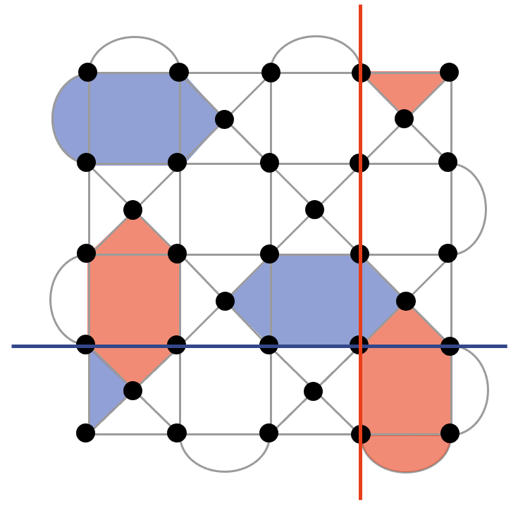
The RSSC naturally overlays the heavy hexagonal lattice as shown in Fig. 1b. We refer to extra qubits for making or mediating measurements as measurement qubits. Each X gauge operator uses a single measurement qubit on the interior, and the weight-2 Z gauge operators on the boundary use three measurement qubits, assuming translation symmetry. Counting these additional ancillary qubits, we operate a distance- code using a subset of the lattice containing qubits.


Due to the natural mapping to the heavy hexagon lattice, the X gauge operators can be measured without extra gates using the circuit in Fig. 3a. Bit-flip errors on the measurement qubit propagate to at most one bit-flip error on the data modulo the gauge group, so there are no space-like hook errors. However the circuits can produce space-time hook errors from a single fault event, just like the surface code.
The Z gauge operators are more difficult to measure but each can be measured using the circuit in Fig. 3b. By inspecting all single-fault events, we conclude that this circuit has the property that any single fault gives rise to at most one X and one Z error on the data modulo the gauge group. Since these are correctable errors for CSS codes, the syndrome measurement circuit is fault-tolerant in the following sense. If faults occur then the output state deviates by at most X errors and Z errors modulo the gauge group. These X and Z errors can be corrected independently as long as there is no mechanism to convert them into Y errors.
On the heavy hexagon lattice, we find that the RSSC has a threshold of nearly for circuit-level noise. Additional details and a comparison with the HHC can be found in Appendix C.
II.3 Other relevant codes
It is worth mentioning other codes that can be directly implemented on the heavy hex layout, which are not included in this study. In particular, Floquet codes Hastings and Haah (2021), Floquet color codes Kesselring et al. (2022), matching codes Wootton (2022) and repetition codes Liepelt et al. (2023). In all these cases, syndrome measurements are made via two-qubit parity operators, for which the qubits on the edges of the heavy hex lattice can be used as auxiliaries.
Repetition codes are very much an outlier in this group since they protect only a logical bit rather than a logical qubit, and have a distance equal to the number of data qubits. We therefore do not include them in our study, since the results are likely be unrepresentative of truly quantum codes.
For Floquet codes, Floquet color codes and matching codes, though a direct implementation of these is possible on the heavy hex lattice, they are more ideally suited to systems in which direct parity measurements are possible Paetznick et al. (2023). Compared to this, implementation with the heavy hex would result in a significant decrease in threshold and performance, and significantly less resilience when there is a bias towards different noise sources Hetényi and Wootton (2023). It is for this reason that we do not include such codes in this study.
III Noise models and methods
In this section we introduce general noise models used in this work. For all models, the circuits are decomposed into a set of operation types, = {cx,h,s,id,x,y,z,measure,initialize,reset}, the first seven abbreviated operation types being the cnot, hadamard, phase, identity, rotations, respectively. For iid, each of the operation types experiences a fault with a depolarizing noise error rate specific to the operation type. Non-identical, independent, distribution (niid) assignments used in this work will be further detailed below. Stabilizer simulations of the noisy circuits are done using the Qiskit software stack.
Decoding is done using minimum weight perfect matching (MWPM) Dennis et al. . The decoder is provided with either all location specific error rate information, called aware condition, or limited to using the lattice averages for each operation type, called naive. Briefly the MWPM method forms a decoding hypergraph of nodes representing Z or X stabilizer measurements. Edges of the graph are weighted according to the available error rate information. A perfect matching algorithm returns a minimum weight set of connecting edges for each syndrome of stabilizer measurements at the nodes that highlight the presence of an error. Aware decoding is used unless otherwise noted. Further details of the simulation method can be found in Sundaresan et al. Sundaresan et al. (2023).
We simulate logical error rates, , for cases composed of different conditions defined from: (i) type of lattice distribution of error rates (i.e., noise model), (ii) code, (iii) decoder type (aware or unaware), and (iv) which distribution parameter is varied, Table 1.
We label the distributions categories as: uniform, normal, non-normal and location specific. The uniform signals that error rates for the faulty circuit operation, and (unless otherwise noted), are set to the same input error rate, , at all lattice locations. The errors are modeled as depolarizing noise. A background error rate, typically negligibly small compared to the is used for the other faulty circuit operations for these test cases unless otherwise noted.
The normal distribution signals that each faulty and location is assigned an error rate drawn from the absolute value of a normal distribution (unless otherwise noted). The normal distribution is defined with an average error rate, and a standard deviation . The errors are again modeled as depolarizing noise. Two steps of averages are done to obtain an output logical error rate. In the first step, the results are averaged for a single device instance of unique fixed error rates at each faulty location. Each shot of a circuit includes rounds of zzxx(xxzz) stabilizer measurements for X(Z) intialization and measurement, respectively. For the second step, an average is formed over a number of device instances that we define as a new distribution of error rates from the error distribution category.
A non-normal, reciprocal-normal distribution is considered in this work that is a proxy, for example, for coherence limited errors and more generally distributions with heavy tails at higher error rates, see appendix A and B. We also examine cases where one to four locations have error rates that are either fixed at or varied between , labeled location (e.g., ’bad’ sites). An errant location assigns increased error rates for the operations and the two qubit operations, , connected to the qubit site. The rest of the lattice error rates are constant, . Further details for each case are indicated in the results sections.
| Variable | N loc. | Code | Decode | ||
| \Distribution | comp. | ||||
| Uniform | S.II,A.C | - | - | R,H | - |
| Normal | - | S.IV.3, A.D | - | R,H | S.IV.3 |
| Non-normal | S.IV.1 | S.IV.1 | - | R | - |
| Location | S.IV.2, A.F | - | S.IV.2 | R,H | A.F |
IV Results
IV.1 Impact of normally distributed coherence times on logical error rates
In this section we describe results from a parameterized error distribution for which the error rate is reciprocally related to a normally distributed random variable, . A physical motivation for this distribution is randomly distributed coherence times, like energy relaxation with a coherence time . We assign an error rate , where is a random variable pulled from a normal distribution with mean, , standard deviation, and is a constant representative of an effective gate time of the qubit operation. We simulate output error dependence on the standard deviation of the normal distribution, , for the RSSC code.
The logical output error rate dependence on uniform is shown in Fig. 4 (a) (see appendix C for more details) and the dependence on varying is shown in Fig. 4 (b). We show the dependence normalized to the average and therefore vary a parameter . The average error rate in Fig. 4 (b) is , an average cx error rate foreseeable in the near future Stehlik et al. (2021). We show the logical error for both X or Z initialization and measurement cases. The output error rate shows an onset of increasing average logical error rate when approaches .
We now discuss the numerics in the context of a simple model that illustrates that the onset of increasing may be understood as the onset of the mean of the input error rate, increasing (i.e., ). We first observe that numerical simulations of logical error rates for normally distributed error rates show no dependence on the standard deviation of the distribution, see appendix D, in contrast with the dependence of the reciprocal normal distribution. To understand this observation, we note that a phenomenological model of the repetition code with normally distributed error rates results in an irrespective of the standard deviation of the error rates, see appendix E. Here we define an average output error of the phenomenological model, , with contributing data sites at indices . Each data site has normally distributed error rates, and an average error rate of all the data, . The phenomenological model provides the insight that random distributed error rates of a faulty type of component will result in an averaged contribution to the output error rate consistent with the numeric result. We conjecture that for a wide range of uncorrelated error rates the average logical error is a function of the average physical qubit error rate, , in contrast to dependence on higher moments of the distribution. On the other hand, we also note that although is not sensitive to changes in , the ’device-to-device’ variance of is predicted to be dependent on , see appendix E.
We return to the observation that the logical error rate increases for when the error rate distribution of the faulty locations is proportional to . The mean of such a distribution depends on the harmonic mean of the distribution. The average is done for a normally distributed distribution, , see appendix B for more details. The values sampled above versus below are unevenly weighted and this leads to a dependence of despite being independent of consequently leading to an increase in .
This behavior is of general interest for any error process that depends reciprocally on a random process such as electronics noise impacting dephasing (e.g., ), although relative weights in the tails could lead to a deviation from the simple picture that the output error rate can be predicted by the average input error rates as if they were uniform error rates. Effects of outliers will be discussed in the following section.


IV.2 Dependence of output error on high infidelity outliers at specific qubit sites
In this section we examine the effect of changing error rate at a limited number of sites while the rest of the error rates for faulty locations are held constant. We ask, for example, how sensitive the logical error rate is to deviations of error rate at a single faulty location from the average?
We first examine the effect of increasing the error rates, , of h, id and all cx operations that include the data qubit located at site 0, Fig. 1 (a). All other error rates are set to . A S-curve behavior is observed as is increased. While is similar to , little effect is observed on , consistent with not being significantly changed, see discussion above. At higher , begins to rise and then saturates. Rapid increase in output error rate begins at an input error rate of approximately 40 times larger than for . A single data qubit location can be relatively faulty compared to the devices average (i.e., ) before the output error rate begins to be substantially degraded. The maximum increase in error is bounded further by the commensurate loss in distance of the code.
To further illustrate the effect of ’knocking out’ data qubits, we simulate output error as a function of uniform input error for instances where 0 to 4 data qubits are set to , Fig. 5. We note that the sites 0 to 4 are along the logical Z operator in the RSSC. The measure X output error jumps after the addition of a single ’bad’ qubit at site 0 and ouput error increases quasi-linearly with the device , Fig. 5 (b). The end points of the sensitivity analysis of output error to varying the of a single ’bad’ qubit at site , Fig. 5 (a), are identifiable in Fig. 5 (b) as indicated. We infer that there are similar S-curves between the other points in Fig. 5 (b).
Increasing the number of ’bad’ data qubits along the Z logical operator leads to monotonic jumps in output error rate. Qualitatively this could be interpreted as the sequential reduction of the effective distance of the code through ’knocking out’ code qubits along a logical operator. The 0 site is along both the logical X and Z operators. ’Knocking out’ the 0 site with a ’bad’ qubit reduces the correcting power of the logical qubit for both X and Z cases. The output error rate of the Z-measurement does not increase very rapidly, however. This behavior qualitatively may be understood as the code maintaining a distance correction for X-like errors combined with a lack of sensitivity of the logical Z-measure to logical-Z-like errors. Further discussion of site specific sensitivity can be found in appendix F.
IV.3 Improved decoding with non-uniform edge weights
Minimum weight perfect matching (MWPM) is used for decoding in the simulations. Weights for each edge in the decoder graph are assigned according to available information about error rates. We now investigate the decoder performance for the case that error rates for each gate operation are available, aware decoding (i.e., Dijkstra algorithm applied to unique edge weights in the decoding graph), in contrast to assuming an average error rate for the gate operations, naive (i.e., edge weights using the average error rate for i, h, cx operations).
An important way that decoding can improve is through resolving ambiguous syndromes for error chains greater than . Random error rate distributions can offer ’tie breaking’ information (see for example appendix G). Improved error rates using aware decoding for random distributions for a phenomenological analysis have already been reported Tiurev et al. (2023). The prominence of ambiguous cases that can be resolved using this information is likely code dependent. To further probe the question of relative decoder effectiveness of aware decoding, we investigate the response of a heavy hex code (HHC) to these two different decoding approaches. The HHC is a hybrid of a surface code and compass code with flag qubits Chamberland et al. (2020); Sundaresan et al. (2023). This combination provides a useful relative view of the effectiveness of aware decoding for these two different codes.
Simulations were carried out for aware and naive and were done for the the (Z) and (X), four different cases, for several distances, Fig. 6. The Z basis corresponds to stronger sensitivity to the surface code like checks and the X basis corresponds to compass code like checks with flag qubits. In both X and Z bases, the aware decoder reduces compared to the naive case and the benefit increases with both decreasing and increasing , consistent with predictions from phenomenological modeling Tiurev et al. (2023). The reduction in is, however, relatively weak for x basis cases and is in general relatively small for these small distance codes. Qualitatively weak improvements from decoder improvements for the X basis were reported in experiments on the HHC even when applying maximum likelihood methods. One contribution noted in that work was that the Z check circuit is susceptible to introducing a high rate of Z errors on the data, particularly because of how deflagging is done, which is difficult to improve with better decoding Sundaresan et al. (2023).

V Discussion
V.1 Screening
During the fabrication process of QPUs, checkpoints can be established where infidelities of qubit operations can be estimated Zhang et al. (2022). Imperfect fabrication processes lead to sets of QPUs each with their own estimated infidelity distributions. Ranking of the QPUs within these sets is useful for selection of which QPUs to ultimately deploy. A predictive pre-selection is desirable, all other considerations assumed to be the same.In the context of these findings, a paradigm of ranking by average input error rate of a dominant faulty circuit operations (e.g., two qubit gate operations) may therefore be an effective starting strategy in the absence of other supporting indicators like logical qubit error simulation.
This strategy might be further refined in the presence of a model for the logical error rate dependence on average input error rate, for example, circuit simulations of a particular code and device layout. In such circumstances, more quantitative evaluation of the sensitivity to differences in average input error, QPU to QPU, come into consideration including a better understanding of shot to shot standard deviation in the logical error rate.
V.2 Sensitivity to ’bad’ location
The impact of one or a limited number of ’bad’ locations is a common question due to many factors ranging from fabrication imperfections to instability in device performance (e.g., spectral diffusion of two level systems Carroll et al. ). Here we loosely define a ’bad’ location as a faulty location for which the infidelity of the gate operation appears to be an outlier relative to the average error rate.
We have observed, in section IV.2, that the sensitivity of the logical error can be relatively weak to an outlier location until the error rate is appreciably larger than the contribution of the average error distribution. The ’bad’ location contribution to the logical error rate is, furthermore, limited as the error rate saturates at roughly the equivalent of the reduction of the code distance by one.
For a simplified order of magnitude estimation example, we might consider identification of ’bad’ two qubit gate locations by assuming a case where the two qubit gate locations are the dominant error rate for the logical error. Then a two qubit location is identifiable as a ’bad’ location when its error rate is: , where is the number of qubits in the encoding. In general the average error distribution has many contributions from the different circuit operations. Each of the operation types have their own relative contributions to the logical error rate.
V.3 Time dynamic noise
Error rates are time dependent in realistic devices. There are a number of sources of time dependence Witzel et al. ; Müller et al. ; de Graaf et al. ; Krantz et al. (2019). A natural question is what logical error rates to expect in the presence of time dynamic noise. In many cases the time dynamics are correlated, which is out of the scope of this analysis. This work, however, does provide insight about the limit of uncorrelated time fluctuations. In this context, the observation that the average logical error rate is not dependent on higher moments of the distribution provides an indication that the logical error rate will converge to an average based on the average of the input error rates when uncorrelated noise processes are also stationary, while the variance of the logical error rates, in contrast, will depend on higher moments. It is left to future work to establish how close this limit approximates experimental cases that can have time and space correlations.
V.4 Pseudothresholds and guidance for design
A device’s qubits performance relative to the pseudothreshold of a code is a predominant concern for design, fab and operation of quantum error correction on a QPU. Pseudothresholds are often estimated using simulations with forms of uniform error rates for types of circuit operations (e.g., two qubit operations). How to assess an actual device’s non-uniform infidelity distibution relative to a code’s pseudothreshold, particularly time varying distributions, without measuring or simulating the specific case (when measurement is not readily available) is a practical problem. This work provides the observation that for uncorrelated noise and surface-like codes, over a relative wide error rate range. The concept of a pseudothreshold therefore is also applicable when framed as an outcome of an average error rate of faulty locations in the error correction circuit. This observation may also be of utility in the context of system design, for which variability in system components are their own source of qubit operation infidelity distributions. System designs therefore will need to assess impact of outliers and variances of their component performances relative to their targets. Analysis based on the average error rates would greatly simplify the challenge of multi-distribution problems, in contrast to analysis of the contributions of multiple distribution each with their own multi-moment parameterizations.
V.5 Modularity
Interest has increased recently in noisy connections between devices to form extended modular quantum error corrected patches Ramette et al. ; Auger ; Nickerson et al. . The impact of a sparse number of high error rate locations (i.e., connection points) on output logical error rates is of central interest in order to provide guidance about design and fabrication tolerances. The logical dependence on ’bad’ qubit sites placed along a logical operator, in this work, is of tangential relevance as it highlights that if the intersecting ’seam’ between modules is placed along a logical operator, it may unnecessarily exaggerate the deleterious impact of the ’seam’ compared to staggering the intersections in a less spatially correlated mode (i.e., sparse random).


VI Conclusion
We have studied independent non-identical noise distributions at circuit level for proxy cases of the surface and compass code families. The circuits are mapped to a heavy hex layout and for this work it is shown how to map a rotated subsystem surface code (RSSC) onto the heavy hex lattice. These cases are of general interest to understand surface and compass code trends, while the particular cases are of direct interest to the application of superconducting qubit quantum error correction Sundaresan et al. (2023).
A central result is that the for the distributions studied in this work, where is the average error rate of one or a combination of dominant faulty circuit operations. Notably, is not a strong function of higher moments of the error distribution over the range of parameters studied. The standard deviation of , , however, does depend on higher moments of the distribution. The independence of is consistent with a phenomenological model of the repetition code which, for a three qubit example is: (see appendix E).
The effect of outliers is examined with simulations of the sensitivity to varying error on a single or few ’bad’ sites. The simulations highlight that begin to appreciably change the logical error rate. The logical error increase, furthermore, is limited and saturates. The saturation qualitatively behaves as if the code distance is reduced by the introduction of the ’bad’ qubit, .
For reference, we discuss a proxy physical example of non-identical error rate, decoherence from energy relaxation which, for example, produces a time dynamic distribution of error rates in superconducting qubits. A normal distribution loosely fits the histogram frequency of measured across devices. We use this example to highlight the importance of the harmonic mean of coherence times as being a relevant measure for estimating . A number of studies in the literature emphasize normally distributed infidelity distributions, which may overlook the importance of the role of higher moments in (e.g., ). Error rates are often reciprocally dependent on coherence times, for example, which are determined by common intrinsic (e.g., fab defects) and extrinsic (e.g., electronics noise) distributions of noise.
Tantalizingly, the non-identical distributions of error rates offer an opportunity in decoding approaches like minimum weight perfect matching. Decoding of syndromes can be hampered by ambiguities for error chains of or greater with the same syndrome. Non-uniform error rates introduce additional information, aware, that might improve decoding relative to naive. As with previous investigators, we observe an improvement in decoding with aware information relative to naive. For normally distributed error rates across the probe operations (i.e., and operations), the improvement increases with increasing of the error rate distribution. It is a possibly interesting future direction to assess how much of a decoding utility the non-uniformity can be.
In summary, we have numerically studied non-identical, independent noise distributions for surface and compass-like codes at a circuit level. We observe several trends that provide heuristic guidance regarding the role of the average in contrast with higher moments of error rate distributions play on the logical error. We also probe the sensitivity of logical error rates to one or a few outlier error rate device locations, which provides additional insight about the role of ’bad’ locations and identification of error rates at these locations that cross-over to being non-negligible relative to the weight of the rest of the error contributions in the circuit. These observation provide practical insights into areas ranging from screening, modularity and system design.
VII Acknowledgements
We thank Ted Yoder for improvements to the circuit shown in Fig. 3b. We thank Kenny Tran for access to computing resources for the numerical simulations. We acknowledge insightful discussions with A. Corcoles, B. Brown, L. Govia, M. Takita, D. McKay, J. Tersoff and T. Yoder. Parts of this research was sponsored by the Army Research Office accomplished under Grant Number W911NF-21-1-0002 and by IARPA under LogiQ (contract W911NF-16-1-0114). The views and conclusions contained in this document are those of the authors and should not be interpreted as representing the official policies, either expressed or implied, of the Army Research Office or the U.S. Government. The U.S. Government is authorized to reproduce and distribute reprints for Government purposes notwithstanding any copyright notation herein.
VIII References
References
- (1) Markus Reiher, Nathan Wiebe, Krysta M. Svore, Dave Wecker, and Matthias Troyer, “Elucidating reaction mechanisms on quantum computers,” Proceedings of the National Academy of Sciences 114, 7555–7560.
- (2) Andrew M. Childs, Dmitri Maslov, Yunseong Nam, Neil J. Ross, and Yuan Su, “Toward the first quantum simulation with quantum speedup,” Proceedings of the National Academy of Sciences 115, 9456–9461.
- (3) Sergey Bravyi, Oliver Dial, Jay M. Gambetta, Dario Gil, and Zaira Nazario, “The future of quantum computing with superconducting qubits,” Journal of Applied Physics 132, 160902.
- (4) Eric Dennis, Alexei Kitaev, Andrew Landahl, and John Preskill, “Topological quantum memory,” Journal of Mathematical Physics 43, 4452–4505.
- (5) Austin G. Fowler, Matteo Mariantoni, John M. Martinis, and Andrew N. Cleland, “Surface codes: Towards practical large-scale quantum computation,” Phys. Rev. A 86, 032324.
- (6) Antonio deMarti iOlius, Josu Etxezarreta Martinez, Patricio Fuentes, Pedro M. Crespo, and Javier Garcia-Frias, “Performance of surface codes in realistic quantum hardware,” Physical Review A 106, 062428.
- (7) Jared B. Hertzberg, Eric J. Zhang, Sami Rosenblatt, Easwar Magesan, John A. Smolin, Jeng-Bang Yau, Vivekananda P. Adiga, Martin Sandberg, Markus Brink, Jerry M. Chow, and Jason S. Orcutt, “Laser-annealing josephson junctions for yielding scaled-up superconducting quantum processors,” npj Quantum Information 7.
- Zhang et al. (2022) Eric J. Zhang, Srikanth Srinivasan, Neereja Sundaresan, Daniela F. Bogorin, Yves Martin, Jared B. Hertzberg, John Timmerwilke, Emily J. Pritchett, Jeng-Bang Yau, Cindy Wang, William Landers, Eric P. Lewandowski, Adinath Narasgond, Sami Rosenblatt, George A. Keefe, Isaac Lauer, Mary Beth Rothwell, Douglas T. McClure, Oliver E. Dial, Jason S. Orcutt, Markus Brink, and Jerry M. Chow, “High-performance superconducting quantum processors via laser annealing of transmon qubits,” Science Advances 8 (2022).
- (9) Michael Hanks, William J. Munro, and Kae Nemoto, “Decoding quantum error correction codes with local variation,” IEEE Transactions on Quantum Engineering 1, 1–8.
- (10) BD Clader, Colin J Trout, Jeff P Barnes, Kevin Schultz, Gregory Quiroz, and Paraj Titum, “Impact of correlations and heavy tails on quantum error correction,” Physical Review A 103, 052428.
- (11) Christoph Berke, Evangelos Varvelis, Simon Trebst, Alexander Altland, and David P. DiVincenzo, “Transmon platform for quantum computing challenged by chaotic fluctuations,” Nature Communications 13.
- Strikis et al. (2023) Armands Strikis, Simon C. Benjamin, and Benjamin J. Brown, “Quantum computing is scalable on a planar array of qubits with fabrication defects,” Phys. Rev. Appl. 19, 064081 (2023).
- (13) Shota Nagayama, Austin G Fowler, Dominic Horsman, Simon J Devitt, and Rodney Van Meter, “Surface code error correction on a defective lattice,” New Journal of Physics 19, 023050.
- (14) Austin G. Fowler and Craig Gidney, “Low overhead quantum computation using lattice surgery,” arXiv:1808.06709 [quant-ph] .
- (15) James M. Auger, “Fault-tolerance thresholds for the surface code with fabrication errors,” Physical Review A 96.
- Li et al. (2019) M. Li, D. Miller, M. Newman, Y. Wu, and K. Brown, “2-d compass codes,” Phys. Rev. X 9 (2019).
- Chamberland et al. (2020) C. Chamberland, G. Zhu, T. Yoder, J. Hertzberg, and A. W. Cross, “Topological and subsystem codes on low-degree graphs with flag qubits,” Phys. Rev. X 10 (2020).
- (18) P. V. Klimov, J. Kelly, Z. Chen, M. Neeley, A. Megrant, B. Burkett, R. Barends, K. Arya, B. Chiaro, Yu Chen, A. Dunsworth, A. Fowler, B. Foxen, C. Gidney, M. Giustina, R. Graff, T. Huang, E. Jeffrey, Erik Lucero, J. Y. Mutus, O. Naaman, C. Neill, C. Quintana, P. Roushan, Daniel Sank, A. Vainsencher, J. Wenner, T. C. White, S. Boixo, R. Babbush, V. N. Smelyanskiy, H. Neven, and John M. Martinis, “Fluctuations of energy-relaxation times in superconducting qubits,” Phys. Rev. Lett. 121, 090502.
- (19) M. Carroll, S. Rosenblatt, P. Jurcevic, I. Lauer, and A. Kandala, “Dynamics of superconducting qubit relaxation times,” npj Quantum Information 8, 132.
- Bravyi et al. (2013) Sergey Bravyi, Guillaume Duclos-Cianci, David Poulin, and Martin Suchara, “Subsystem surface codes with three-qubit check operators,” Quantum Information & Computation 13, 963–985 (2013).
- Poulin (2005) D. Poulin, “Stabilizer formalism for operator quantum error correction,” Phys. Rev. Lett. 95 (2005).
- Sundaresan et al. (2023) Neereja Sundaresan, Theodore J. Yoder, Youngseok Kim, Muyuan Li, Edward H. Chen, Grace Harper, Ted Thorbeck, Andrew W. Cross, Antonio D. Córcoles, and Maika Takita, “Demonstrating multi-round subsystem quantum error correction using matching and maximum likelihood decoders,” Nature Communications 14 (2023).
- Higgott and Breuckmann (2021) Oscar Higgott and Nikolas P. Breuckmann, “Subsystem codes with high thresholds by gauge fixing and reduced qubit overhead,” Phys. Rev. X 11, 031039 (2021).
- Brown et al. (2019) N. Brown, M. Newman, and K. Brown, “Handling leakage with subsystem codes,” New Journal of Physics 21 (2019).
- Hastings and Haah (2021) Matthew B. Hastings and Jeongwan Haah, “Dynamically Generated Logical Qubits,” Quantum 5, 564 (2021).
- Kesselring et al. (2022) Markus S. Kesselring, Julio C. Magdalena de la Fuente, Felix Thomsen, Jens Eisert, Stephen D. Bartlett, and Benjamin J. Brown, “Anyon condensation and the color code,” (2022), arXiv:2212.00042 [quant-ph] .
- Wootton (2022) James R Wootton, “Hexagonal matching codes with two-body measurements,” Journal of Physics A: Mathematical and Theoretical 55, 295302 (2022).
- Liepelt et al. (2023) Milan Liepelt, Tommaso Peduzzi, and James R. Wootton, “Enhanced repetition codes for the cross-platform comparison of progress towards fault-tolerance,” (2023), arXiv:2308.08909 [quant-ph] .
- Paetznick et al. (2023) Adam Paetznick, Christina Knapp, Nicolas Delfosse, Bela Bauer, Jeongwan Haah, Matthew B. Hastings, and Marcus P. da Silva, “Performance of planar floquet codes with majorana-based qubits,” PRX Quantum 4, 010310 (2023).
- Hetényi and Wootton (2023) Bence Hetényi and James R. Wootton, “Tailoring quantum error correction to spin qubits,” (2023), arXiv:2306.17786 [quant-ph] .
- Stehlik et al. (2021) J. Stehlik, D. M. Zajac, D. L. Underwood, T. Phung, J. Blair, S. Carnevale, D. Klaus, G. A. Keefe, A. Carniol, M. Kumph, Matthias Steffen, and O. E. Dial, “Tunable coupling architecture for fixed-frequency transmon superconducting qubits,” Phys. Rev. Lett. 127, 080505 (2021).
- Tiurev et al. (2023) Konstantin Tiurev, Peter-Jan H. S. Derks, Joschka Roffe, Jens Eisert, and Jan-Michael Reiner, “Correcting non-independent and non-identically distributed errors with surface codes,” Quantum 7, 1123 (2023).
- (33) Wayne M. Witzel, Malcolm S. Carroll, Lukasz Cywinski, and S. Das Sarma, “Quantum decoherence of the central spin in a sparse system of dipolar coupled spins,” Phys. Rev. B 86, 035452.
- (34) Clemens Müller, Jared H. Cole, and Jürgen Lisenfeld, “Towards understanding two-level-systems in amorphous solids – insights from quantum circuits,” Rep. Prog. Phys. 82, 124501.
- (35) S. E. de Graaf, L. Faoro, L. B. Ioffe, S. Mahashabde, J. J. Burnett, T. Lindström, S. E. Kubatkin, A. V. Danilov, and A. Ya. Tzalenchuk, “Two-level systems in superconducting quantum devices due to trapped quasiparticles,” Science Advances 6.
- Krantz et al. (2019) P. Krantz, M. Kjaergaard, F. Yan, T. P. Orlando, S. Gustavsson, and W. D. Oliver, “A quantum engineer’s guide to superconducting qubits,” Applied Physics Reviews 6, 021318 (2019).
- (37) Joshua Ramette, Josiah Sinclair, Nikolas P. Breuckmann, and Vladan Vuletić, “Fault-tolerant connection of error-corrected qubits with noisy links,” arXiv:2302.01296 .
- (38) Naomi H. Nickerson, Ying Li, and Simon C. Benjamin, “Topological quantum computing with a very noisy network and local error rates approaching one percent,” Nat Commun 4, 1756.
- (39) E. Paladino, Y. M. Galperin, G. Falci, and B. L. Altshuler, “1/f noise: Implications for solid-state quantum information,” Rev. Mod. Phys. 86, 361–418.
- Higgott (2021) Oscar Higgott, “PyMatching: A fast implementation of the minimum-weight perfect matching decoder,” arXiv:2105.13082 (2021).
Appendix A coherence example
A.1 Averaged distribution
Energy relaxation is a leading source of decoherence in superconducting qubits. A spread of relaxation times, , are observed across many qubit devices at present. The single and two qubit gate infidelities depend on these coherence times leading to a source of non-uniform infidelity distribution across a device. The energy relaxation rates, furthermore, fluctuate in time over a wide range of time scales Klimov et al. ; Müller et al. ; Paladino et al. .
An example distribution for a 20 qubit device is shown in figure 1 (a) Carroll et al. . The distribution is representative of several common features of distributions observed in devices. We note that the histogram and ’normal’-like distribution is, however, not necessarily an absolutely complete representation of the actual distribution. That is the distribution (1) may include some cases that are non-exponential decays due to strong couplings to defects; (2) may miss some fluctuations due to limited measurement time resolution of a non-white power spectral distribution; and (3) may miss some cases in the low coherence time tail of the distribution because the was immeasurably short.
In this work we primarily focus on the normal-like part of the distribution as this is sufficient to highlight some of the key implications of independent but non-identically distributions (i.n.d.) for quantum error correction. We note that there are a variety of sources of non-uniform infidelity distribution in devices Krantz et al. (2019); Paladino et al. . The energy relaxation distribution is a proxy for the more general problem of non-uniform, fluctuating infidelity distributions.
A.2 How normal are the measurable distributions?
The times for all qubits were collected for a period over 9 months, a set of 6140 values, shown in the main text, Fig. 1. A representative histogram of a measured daily for just one qubit is shown in Fig. 7. A Kolmogorov-Smirnov null hypothesis test was done for each qubit, for which the null hypothesis is that the distribution is indistinguishable from a normal distribution. The test statistic was 0 and the p-value was greater than 0.999 indicating the normal distribution was indistinguishable from the measured distribution to the limits of accuracy of this statistical measure. We caution, as noted above, that the distribution has some bias through neglect of outlier instances when the qubit’s is so short that it is immeasurable.
The standard deviation of the distribution for each qubit is shown in Fig. 7 (b). Most qubits show standard deviations of . The details of the measurement are described in a previous publication Carroll et al. .

Appendix B Mean of distribution dependent on reciprocal of normally distributed random variable
Many error rates depend on the reciprocal of a parameter, for example when the error rate is dominated by coherence time it can be approximated as , where is the error rate and is a coherence time.
In this appendix we are concerned with the error rate mean when the ’reciprocal parameter’ is a normally distributed random variable. We will show that for a normally distributed ’reciprocal parameter’ (e.g., ) that the new random variable’s mean is no longer constant rather it depends on , the standard deviation of the ’reciprocal parameter’.
We start by defining a ’reciprocal parameter’ random variable that is normally distributed:
| (9) |
where is and is the standard deviation of the distribution.
We now consider a new random variable, the error rate, formed with the ’reciprocal parameter’, . The probability of a qubit site having an error rate of is therefore .
The mean of the error rate distribution is:
| (10) | |||
To see analytically that the mean will depend on we evaluate the integral in the approximation of very small for which we may Taylor expand around . This simplification allows integration over all values but is implicitly inaccurate for approaching 0, however, it qualitatively shows the trend for the largest weight of the distribution. The average error in this simplistic approximation is:
| (11) | |||
Using well established identities for the integration of the product of the Gaussian function and polynomials, for example:
| (12) |
where , and . To 2nd order, dropping higher terms, the average of the error becomes:
| (13) |
for which we see that increases as a quadratic function of . Odd polynomials do not contribute to the integration over the even Gaussian interval and better approximation would include higher even order terms. Overall the 2nd order approximation grossly underestimates the quantitative dependence of on because the approximation neglects contributions from the values closer to 0 that can be very large but qualitatively confirms that an anticipated increase in average error as increases. For reference we numerically evaluate truncated for s and in Fig. 8 and show its dependence on .


Appendix C Numerical threshold estimates for the RSSC on the heavy-hexagon lattice
The RSSC syndrome measurement circuit is a sequence of X and Z gauge operator measurement cycles. The X measurements are scheduled in 3 parallel CNOT layers using time steps shown in Fig. 10. The Z measurements occur in two stages where we measure all of the left-pointing triangles followed by all of the right-pointing triangles. In each stage, the circuits act on disjoint sets of qubits, so we can schedule them independently according to Fig. 9.


To evaluate the logical error probability, we construct quantum memory circuits that prepare, store, and measure logical or states. These circuits prepare all of the data qubits in either or , respectively, measure X and Z gauge operators in some sequence, and measure all of the data qubits in the or basis, respectively. We consider sequences of X and Z gauge measurements represented by the string for positive integers and . This string means we apply the Z measurements times followed by the X measurements times, and the whole sequence is repeated times. We set the total number of ZX measurements to and iterate over . As in Higgott and Breuckmann (2021), we find that optimizes the logical error rate. In this case, roughly half the syndrome bits are computed from the product of eigenvalues of a pair of gauge operators, while the other half is given directly by the eigenvalues of the gauge operators. The matching subroutine in the decoder is implemented using PyMatching Higgott (2021).
We simulate these circuits using a standard Monte-Carlo simulation wherein we sample from a collection of faulty circuits. Faulty gates are modeled as ideal gates followed by a Pauli channel that applies with probability a uniformly random non-identity Pauli error on all output qubits. Each type of operation and idle qubit can fail. Faulty preparations and measurements flip their outputs with probability . The simulation is considered a failure if the logical measurement outcome is incorrect. The logical qubit we store in the memory is exposed to a logical Pauli channel with parameters , , and . When we prepare and measure in the basis, the simulation provides an estimate of the logical Pauli error probability , and when we measure in the basis we estimate .
The logical and operators have minimum weight and are related by a transversal Hadamard gate followed by a reflection about the diagonal, so they we expect them to have comparable logical error probabilities that are suppressed to the same order in the code distance. The logical operators of the code also have minimum weight , but there is only one coset representative with this weight, whereas there are coset representatives of logical weight . Therefore, we expect logical Y errors to be suppressed. For this reason, we choose to (over)estimate the total logical error rate as the total of the estimates from the and basis circuits.
Simulation results are shown in Fig. 11 and Fig. 12. These results suggest a threshold of nearly for the RSSC on the heavy-hexagon lattice using a circuit-level noise model. A distance- code is close to break-even at and its logical error rate rapidly decreases to below as approaches .


For the purpose of comparison, we carry out simulations of the HHC using the same parameters and syndrome measurement schedules as the RSSC. When we decode the HHC, we choose to use a simple deflagging procedure Sundaresan et al. (2023) rather than dynamically modifying the edge weights in the decoding graph as in Chamberland et al. (2020). As before, the logical error rate is optimized by choosing , so we conclude that both codes’ logical error rates are improved by schedule-induced gauge fixing. Figure 13 compares the estimated total logical error rate. We find that the HHC and RSSC have nearly identical total logical error rates for distances , , and , but the RSSC exhibits superior logical error rates at higher distances. This is expected behavior because the RSSC has an asymptotic threshold whereas HHC does not.


Appendix D Normal distributed error rate simulations
We numerically examine the dependence of the logical output error rate on error rates selected randomly for h, i and cx at each site for the RSSC. The error rate is drawn from a normal distribution with a standard deviation parameterized as and the error rate is held constant through out the simulated circuit schedule for each instance. The average output error rate converges to the uniform case, Fig. 14 (a). Increasing standard deviation, , in the input error distribution does show a dependence in standard deviation of , instance to instance, Fig. 14 (b). Qualitatively this is also consistent with what is expected from a phenomenological repetition code, appendix E.
Appendix E Noise model cases of the three qubit code
E.1 Case 0: Uniform error for 3 qubit repetition code
We consider a few simple noise models for a three qubit majority vote code to provide insight about the effect of bias on logical qubit error rate when there is a normally distributed persistent bias selected for each qubit operation.
We ask what is the error rate, , defined as the probability that the code reports an incorrect output value from the majority vote after a single round of measurements of the three qubits. For a simple case, case 0, the qubits have the same probability of error, (e.g., a Bernoulli-like binary trial). The probability of an error can be expressed as .
E.2 Case 1: Persistent biased single qubit noise
We now turn to a second case, case 1, where we examine how is effected by adding a random error bias on each qubit site. We substitute unique and persistent error probabilities at each of the sites, (e.g., biases on the single qubit operations). The probability of failure for a three qubit example with can then be expressed as,
| (14) |
simplifying to:
| (15) |
We now define the error rate at the qubit as for which is the explicit bias error rate on the qubit. We consider the case where the is persistent shot to shot for a device instance . The unique draw for all qubits, , describes an error rate, . That is, a particular device instance is described by with an error rate .
We are interested in how , the error rate for the device instance and depend on the biased error. More explicitly we have in mind that the probability of drawing for a particular site is described by the function, (i.e., ). We now explicitly express the error rate, , as a function of the bias error rates for a particular device instance and in the context of the three qubit example:
| (16) | |||
and after reorganizing
| (17) | |||
The probability of a particular error rate is now a random variable defined by the sum and product of independent normal distributions of . Different devices will have different biases leading to a set of device instances with error rates of . A particular instance will have an error rate set by and leading to a sequence of Bernouli ’trials’ with average error and .
Through averaging over the span of the set of device instances and using the property , for independent random variables and for , the error rate averaged over many device instances simplifies eqn. 17 to:
| (18) |
We also ask how the average variance may depend on . The variance is averaged over all instances. Explicitly this becomes:
| (19) | |||
Observing that and keeping only the order terms eqn. 19 simplifies to:
| (20) | |||
where for illustration we parameterize the standard deviation as as in the body of the paper. The variance averaged over all instances depends on the standard deviation, and higher moments of in contrast to the that depends only on the input average error rate .
Appendix F Output error sensitivity to different functional sites
In this appendix we illustrate the general trends and relative sensitivity of ’bad’ functional sites in a distance 3 HHC, Fig. 15. The S-shape behavior is generally repeated and the onset of increased output error is also qualitatively similar as described in the main text. That is, there is relatively small increase in until is large enough to begin to shift . We see, however, that there are differences in magnitude of sensitivity and some sites are more or less sensitive to X or Z initialization and measurement, a consequence of their specific roles in the measurement of the stabilizers. We also show the difference in error rates for different decoding choices aware (red or blue) and naive (green).

Appendix G Decoder notes
A minimum weight perfect matching decoder was used for all results in this work. As described in Sundaresan et al. Sundaresan et al. (2023) the perfect matching algorithm considers X and Z errors separate. The algorithm finds the minimum weight perfect matching in a graph to associate the syndrome with a particular error. A graph is formed of vertices representing error-sensitive events, V, and hyperedges representing the correlations between the events caused. The probabilistic circuit errors of each operation combine to form the correlation for each edge. There is a graph for each the X and Z errors. Edge weights are set as , where is the edge probability estimated from the leading order of the polynomial error rate associated with the parameterized gate operation error rates. The naive decoder assumes that the error rates are the same for gates of the same kind of operation, while the aware decoder uses the error rate that is actually at each site (e.g., selected from the random distribution). The decoder used in this work is the same as that used in Sundaresan et al. Sundaresan et al. (2023) in which the details of the decoder are more extensively discussed.
Appendix H Complementary simulations for bad qubits with bias noise and distance dependences
In this appendix we illustrate the dependence on different aspects of high infidelity outlier error, complementing the example discussed in the main text. In figure 16 (a) we first show the distance dependence of when there is a single ’bad’ qubit in the corner site 0. The of the ’bad’ qubit is increased while the other errors are held constant as in the main text. One observation is that the error saturates in a qualitatively similar way for each distance.
In figure 16 (b) we examine the bias dependence by setting the error rate for ZI, ZZ and IZ to when linked to the ’bad’ qubit site(s). The bad qubits are sequentially chosen along the Z logical operator. Depolarizing noise is still applied to all other locations. When the logical state is prepared and measured in the Z basis, it is insensitive to the additional ’bad’ Z errors. Qualitatively, when preparing and measuring in the X basis, a similar weak response to XI, XX and IX error is correspondingly observed (not shown). The relative sensitivity is an example of the Z vs. X related response to biased ’bad’ qubit noise.

