Stoner ferromagnetism in low-angle twisted bilayer graphene at three-quarters filling
Abstract
We present a theoretical investigation of the magnetic properties exhibited by twisted bilayer graphene (TBG) systems with small twist angles, where the appearance of flat minibands strongly enhances electron-electron interaction effects. We show that, at three-quarters filling of the conduction miniband, the Stoner mechanism induces a ferromagnetic polarization in the AA-stacking regions, which aligns with recent experimental observations. Our approach models the electronic properties by a tight-binding Hamiltonian combined with a Hubbard mean-field interaction term. We employ a real-space recursion technique to self-consistently calculate the system’s local density of states and use our method to investigate the magnetic properties of small-angle TBG at three-quarters filling. The recursion method’s efficiency makes it possible to address extremely large superlattices through a full real-space approach. We validate our procedure by comparing it with mean-field momentum-space calculations from the literature, which identify a magnetic phase in charge-neutral TBGs.
I Introduction
Twisting two layers of graphene by a specific angle has led to the discovery of a wealth of unexpected phenomena [1, 2]. Particularly intriguing is the experimental discovery of insulating phases and superconducting states [3, 4] in small-angle twisted bilayer graphene (TBG) systems, which has opened new paths for the investigation of graphene systems [5, 6, 7, 8, 9, 10, 11, 12, 13, 14, 15]. This line of investigation, known as twistronics [16], has rapidly attracted a large and active community of researchers in condensed matter physics and materials science [2, 17].
The origin of these remarkable phenomena is attributed to the appearance of flat electronic bands in low-angle TGBs near the charge neutrality point (CNT) [18, 19], as explained by the continuum model [20, 21, 22, 23]. The corresponding electronic states are localized, leading to enhanced electron-electron interaction effects. From a theoretical point of view, the challenge is to treat a system with a unit cell that has thousands of atoms with (strongly) interacting electrons.
The focus of our paper is to present a mean-field approach that deals with this issue, being capable of addressing systems with very large Hilbert spaces. As a showcase, we address the magnetic properties of low-angle TBG systems at finite doping. The motivation is a recent experiment [24] that observed the emergence of a ferromagnetic phase in a TBG with a twist angle at 3/4 filling of the conduction miniband. The experiment also observed a chiral edge state. These findings have been nicely interpreted by the presence of flat bands having non-zero Chern numbers [25, 26], originated from the rotational alignment of the TBG to the hBN substrate that gives rise to band topological effects, and originated from the flat bands having non-zero Chern numbers. Our study does not challenge this theory. We rather add another possible mechanism to explain the ferromagnetic phase.
The onset of magnetism in graphene-based systems has been intensively studied, both experimentally and theoretically [27]. The latter span a wide variety of settings, such as zero-dimensional graphene nanofragments [28, 29, 30], one-dimensional graphene nanoribbons [31, 32, 33, 34, 35, 36], defect-induced magnetism in bulk graphene [37, 38]. The description of magnetic moments induced by edge terminations and vacancies has been addressed by both ab initio calculations and the tight-binding approximation with an on-site Hubbard electron-electron interaction term. The magnetic properties of these systems are nicely described by a mean-field theory, with the exception of vacancy-induced Kondo correlations [39, 40, 41].
In this paper, we employ a tight-binding Hamiltonian with a mean-field Hubbard on-site interaction term to compute the low-energy electronic and magnetic properties of low-angle TGBs. In particular, we study the Stoner magnetization at -filling of the conduction miniband of TBGs with . We use the Haydock-Heine-Kelly (HHK) recursive technique [42, 43, 44, 45] to calculate the spin-resolved LDOS as a function of the twist angle . Being an order method, the HHK method makes possible to compute the Green’s functions of TBG with very large primitive unit cells. The latter combined with a self-consistent mean-field calculation allows us to investigate the electron localization properties and the magnetization of TBGs at arbitrary filling factors of the flat minibands.
The paper is organized as follows. In Sec. II we review the geometric properties of commensurate TBG moiré structures, present the Hamiltonian model, and the numerical method developed for this study. In Sec. III we discuss the LDOS of low-angle TBG rigid and relaxed strucutures. First, we show our results for non-interacting electrons. Next, we calculate the magnetic properties of TBGs at the charge neutrality point (CNP). The excellent agreement between our results and those of Ref. [46], discussed in App. A, serves to validate our method. Finally, we investigate the magnetic properties of a TBG system with at 3/4 filling and find the emergence of a ferromagnetic phase, in line with recent experiments [24]. We present our conclusions in Sec. IV.
II Theory and methods
II.1 TBG geometric and symmetry properties
The stacking geometry of TBGs is characterized, as standard [20, 47, 48], by the twist of one graphene layer with respect to the other around a given site starting from the AA-stacked bilayer, forming a moiré pattern. We describe a TBG system by twisting the upper layer at an angle as described in Ref. [20, 21]. The primitive lattice vectors of the bottom layer are and with the carbon-carbon bond length Å, and those of top layer as , where is the rotation matrix. In this study, we take the spacing between graphene layers as Å for non-relaxed lattices [19].
The lattice structure of a TBG system is commensurate if the periods of the two graphene layers match, giving a finite unit cell. Hence, the periodicity condition requires the lattice translation vector of the bottom (unrotated) layer and in the top (rotated) layer, with and integers, to coincide. The twist angle for a commensurate structure is related to by [49, 50, 51]
| (1) |
with a lattice constant
| (2) |
The commensurate unit cell contains atoms.
Due to the symmetry of the honeycomb lattice, when the translation vector of the top layer is fixed to , a twist at an angle transforms the AA-stacked bilayer into itself. In turn, a twist by transforms the bilayer from AA- to AB-stacking. TBGs with and are mirror images that share equivalent band structures [49].
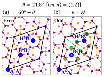
Each graphene layer is constituted by two sublattices, and . The commensurate structures occur in two different forms distinguished by their sublattice parities [50, 51]. Figure 1(a) shows an example of an even commensurate structure under sublattice exchange. It is characterized by having 3 three-fold symmetric positions that correspond to the stacking of the and sites and by hexagonal centers that overlap, . In contrast, Fig. 1(b) shows an odd commensurate structure. Here, the top and bottom coinciding sites correspond to at the origin, and the two remaining three-fold symmetric positions are occupied by (or )-sublattice sites of one layer aligned with the hexagon centers (or ) of its neighbor layer. Therefore, the angles and followed by a relative translation of the upper layer by form commensurate partners with unit cells of equal areas but opposite sublattice parities.
A TBG with is a special case, since its crystal structure is its own commensurate partner and corresponds to an elementary two-dimensional quasicrystalline lattice [52, 53, 54].
Here, we work with odd commensurate structures. In Fig. 1(b), the carbon atom sites, indicated by the green disks, are equivalent due to the three-fold symmetric positions and two-fold rotation axis (green dashed line). These symmetry properties allow us to reduce the numerical computation by identifying the equivalent sites within the primitive unit cell.
Lattice relaxations have been shown to significantly influence the electronic states of low-angle TBGs [55]. Our calculations, which incorporate both in-plane and out-of-plane lattice relaxations, are implemented as follows: For a given twist-angle we determine the atomic relaxation positions of the lattice structures defined above using the Large-scale Atomic/Molecular Massively Parallel Simulator (LAMMPS) [56]. The energy minimization process involves both non-bonded and bonded interactions to accurately model the system. Non-bonded interlayer interactions are handled using a registry-dependent interlayer potential specifically designed for graphene/hBN heterostructures [57, 58, 59], with a cutoff distance of 16 Å, ensuring that all relevant interlayer forces are considered. The parameters for the registry-dependent potential are given in [60]. Bonded intralayer interactions are modeled using the Tersoff potential [61, 62], which is well-suited for describing the covalent bonding in carbon-based materials like graphene. The lattice structure relaxation calculations are performed with an energy tolerance criterion set to eV per atom [63].
II.2 Model Hamiltonian
We model the electronic properties of low-angle TBG systems using the effective Hamiltonian
| (3) |
where stands for the TBG tight-binding Hamiltonian and for a Hubbard on-site electron-electron interaction term [27, 64].
The tight-binding Hamiltonian reads
| (4) |
where the operators and annihilate and create an electron with spin at site , respectively. is the transfer integral between the Wannier electronic orbitals centered at the carbon sites and . The transfer integral , where , depends on the interatomic distance and on the relative orientation between orbitals. is parameterized as [19, 49, 65]
| (5) |
with
| (6) |
| (7) |
Here, eV, eV, and is the decay length of the transfer integral [65, 19]. The transfer integral for Å is exponentially small and can be safely neglected. The intra- and interlayer hopping matrix elements have been determined by fitting the dispersion relations of graphene monolayer and graphene AB-stacked bilayer obtained from ab initio calculations [19].
The Hubbard term reads
| (8) |
where is the spin-resolved electron number operator at site . The parameter gives the magnitude of the on-site Coulomb repulsion [64, 27]. The magnitude of in graphene systems is has been extensively discussed [66, 67] with estimates that vary from . In this study we consider, unless otherwise stated, .
We solve the TBG Hamiltonian for a given filling factor in the mean-field approximation. As standard, we write and neglect the quadratic terms in that are responsible for electronic correlations. The mean field Hubbard Hamiltonian reads
| (9) |
The last term is a constant for a given local magnetic configuration and can be absorbed in the chemical potential.
II.3 Numerical method
Let us now describe how the computation of the ground state charge density and magnetic properties are implemented.
Due to the large number of atoms in a low-angle TBG primitive cell, even mean-field calculations can be computationally very costly. Several effective Hamiltonian models have been developed to reduce the numerical effort [68, 46, 69, 70]. Here, we perform a full real-space calculation using the HHK recursive method, which is very efficient to compute the single-particle LDOS of large systems. The HHK method [43, 44, 45, 42] puts forward a very efficient Lanczos-like recursive procedure that transforms an arbitrary sparse Hamiltonian matrix in a tridiagonal one. Next, it evaluates the diagonal Green’s function in real space by a continued fraction expansion, which is much more numerically amenable than a full diagonalization.
By a suitable choice of the chemical potential, our approach allows us to consider charge neutral as well as systems with a finite doping, namely, , where is the number of electrons in excess to the CNP and is the area of the TBG moiré cell with atoms.
We implement the self-consistent mean-field calculation as standard:
() We start with an initial set of occupation numbers , with the constraint , where the sum runs over all sites of the moiré unit cell, set by the considered doping. The occupations can be chosen randomly or respecting some given symmetry condition.
() Using the HHK recursion technique [42, 43, 44, 45], we compute the LDOS of the electronic system defined by the Hamiltonian, Eq. (3). The spin-resolved LDOS at a given site can be written as
| (10) |
In practice, the regularization parameter is considered as finite and its magnitude can be attributed the self-energy correction due to disorder, that is ubiquitous in graphene systems. The HHK method enables us to compute the LDOS with operations and the DOS with . Hence, it is much more efficient than direct diagonalization, which demands operations.
() Next, we determine , the average electron occupation number with spin at the site . In general, at a given temperature , reads
| (11) |
with , where , is Boltzmann constant, and is chemical potential. At zero absolute temperature, is equal to the Fermi energy and the Fermi distribution becomes a step function. For simplicity, here we consider . As standard, the Fermi energy (or the chemical potential ) is determined by the doping.
() We examine whether the output occupation numbers coincide with the input ones, within a tolerance of . If the answer is positive, we end the self-consistent loop. If not, we return to (). The computation of the updated spin densities is then repeated iteratively until all values of are converged.
The self-consistent solution provides the spin polarization at the th site,
| (12) |
The is translated in a local magnetization , where is the Bohr magneton and the electron -factor is . Hence, the total magnetization per moiré cell reads
| (13) |
We study two cases: , corresponding to the CNP, and corresponding to -filling of the conduction miniband [24]. For the CNP case, a previous theoretical study working in reciprocal space has predicted that low-angle TBG systems have an antiferromagnetic ground state [46]. In this case, we find computationally convenient to start the self-consistent loop with the configuration: , , and , where . For the -filling case, we start with a random set of with the constraint , where .
III Results
We begin this section by presenting a study of the single-particle LDOS of TBG systems with a focus on the formation of low-energy minibands at small twist angles . Next, we use the obtained LDOS to calculate the magnetization of low-angle TBG systems using the self-consistent procedure outlined in Sec. II.3.
III.1 Non-interacting electronic densities
We compute the local electronic properties of TBGs using the HHK recursion method [42, 43, 44, 45]. Being a real space approach, the HHK calculations take advantage of the symmetry properties of the odd commensurate TBG structures discussed above. We have numerically verified that the predicted equivalent sites indeed display the same LDOS. This is used to reduce the numerical effort by a factor of 6. For calculational convenience, the regularization factor is set to be meV. We return to this point later on.
To highlight the sites with the most prominent enhancement of the LDOS in TBGs, we consider the moiré region where the AA stacking is placed at the center of the TBG primitive unit cell. Figure 2(a) shows the LDOS for a moiré unit cell with corresponding to a twist angle containing 6076 carbon atoms. The AB- (or BA-) stacking region is zoomed in the inset. Close to the CNP, well-localized states are found in the AA-stacking region, leading to an enhanced LDOS on atoms around the AA stacking, with much smaller LDOS at AB- and BA-stacking regions, in agreement with previous studies [18, 19].
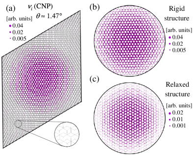
Figures 2(b) and 2(c) show the LDOS at the CNP, , for rigid and relaxed lattice structures with within the circular area of radius of Å, centered at the AA dimer site (or site). The rigid lattice structure shows a LDOS maximum, , that is twice as large as the one computed for the relaxed lattice. For both rigid and relaxed lattices, decays radially with respect to the AA dimer site. However, the LDOS decays more rapidly for the reconstructed lattices due to in-plane relaxation, which reduces the AA-stacking area. In contrast, there is no significant contrast in the LDOS at the CNP in the AB-stacking region, , for either rigid or relaxed lattices.
Figures 3(a) and (b) show the LDOS at the AA dimer site as a function of the energy around the CNP energy, , for , , and , that belong to the family of odd commensurate moiré structures with , for both rigid and relaxed lattices, respectively. Here we use meV. The appearance of the central peak can be interpreted in terms of the continuum model [21], which associates the enhancement of the LDOS at the vicinity of the magic angle to the formation of a flat band at the CNP. Figure 3(c) displays the evolution of the AA dimer site LDOS at the CNP as a function of the small twist angles for the family of rigid and relaxed lattice structures.
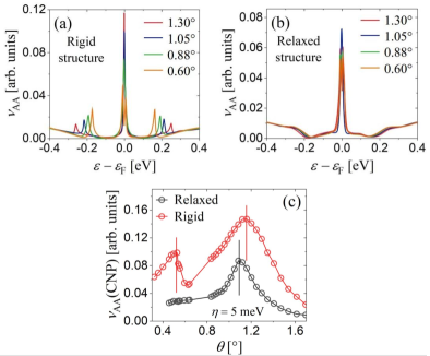
Figures 3(a) to (c) show that when the twist angle decreases, the LDOS of the AA-stacking region increases significantly at the CNP. For the rigid lattice structures, the maximum of the peak appears at the twist angle of [red vertical line in Fig. 3(c)] corresponding to with 9748 carbon atoms within the moiré cell. For the structures considered here, this twist angle is the closest to the first magic angle predicted by the continuum model [21, 23]. We find that the flat-band peak width is larger in the relaxed TBG systems than in the rigid counterpart. The maximum of the LDOS peak appears at [black vertical line in Fig. 3(c)], corresponding to with 11164 carbon atoms within the moiré cell, indicating that lattice relaxation shifts the LDOS peak towards lower twist angles.
Figure 3(c) shows another peak maximum at the twist angle close to (red vertical line), corresponding to with carbon atoms within the moiré cell for the rigid TBG systems. This twist angle is the closest to the second magic angle predicted by the continuum model [21]. In Fig. 3(a), as the twist angle decreases, the satellite peaks around the main one, both in the valence and conduction band, become increasingly intense and move closer to the CNP. In distinction, for relaxed TBG systems, neither the satellite peaks around the main one nor the second magic angle are observed in the electronic properties of twist angles below [71, 72]. In contrast, we find that the van Hove singularities at the AB-stacking region are not depleted, but merely shifted due to lattice relaxation (not shown here), in line with the DOS reported in Ref. [55].
Let us now depart from the CNP and discuss finite doping. Figure 4(a) shows the DOS of the single-particle miniband of a TBG with . Anticipating the appearance of a gap at the CNP when the interaction is switched on, we define a valence and a conduction miniband separated at the CNP. The red area represents the half-band filling of a TBG system where the Fermi energy is at the CNP. This filling corresponds to 4 electrons per moiré cell in the valence miniband. The green area represents the electron doping at the filling of the conduction miniband. This doping corresponds to 3 electrons per moiré cell in excess of the CNP at a Fermi energy meV.
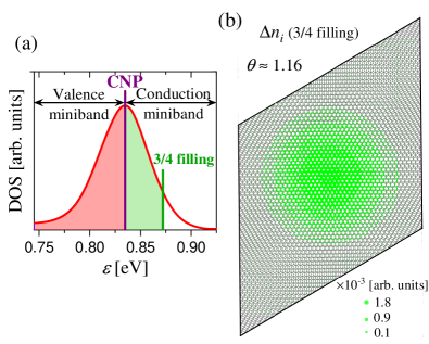
Figure 4(b) shows the carrier distribution in excess to the CNP distribution within the moiré unit cell for . The areas of the green disks are proportional to the carrier occupation number at the atomic site , . Owing to the localized LDOS, see Fig. 2, the carrier distribution is also concentrated at the AA-stacking region.
III.2 Magnetism at 3/4-filling of the conduction miniband
Let us now examine the ferromagnetic phase in rigid and relaxed TBG systems with a twist angle at -filling of the conduction miniband whose origin has been the subject of discussion in the literature.
We consider an odd commensurate lattice with corresponding to 9748 carbon atoms. Our results are obtained by following the self-consistent procedure described in Sec. II.3 for a finite doping. Here, we set . It is worth to note that we find that a small regularization parameter, such as meV, is not essential for obtaining converged results in the interacting case, thereby saving computational cost. In our study, we have carefully selected an value that is sufficiently large to ensure accurate integrated DOS and occupation near the Fermi energy, while remaining small enough not to influence the mean-field calculations. The optimal value may vary between 5 and 25 meV depending on the stacking region considered.
Figures 5(a) and (c) display the local spin polarization, , within a circular area with a radius of Å centered at the AA dimer site for rigid and relaxed TBG systems, respectively. These results show that the ground state is ferromagnetic as characterized by the imbalance between and in the AA stacking region. Since the spin polarization is largest at the regions of enhanced LDOS, we attribute the emergence of ferromagnetism to the Stoner instability mechanism.
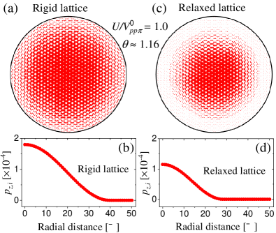
Figures 5(b) and (d) show the local spin polarization, , as a function of the distance from the AA dimer site for rigid and relaxed TBG systems, respectively. The spin polarization is largest at the AA dimer site and becomes smaller as increases and eventually vanishes as the th site approaches the AB non-dimer position.
Since the ground state is ferromagnetic, the total magnetization is not zero. For the rigid lattice structure, we have a maximum local spin polarization of approximately at the AA dimer site, and we find that the total spin polarization per moiré cell is and . However, for the relaxed lattice structure, the maximum local spin polarization is at the AA dimer site with total spin polarization per moiré cell is and . Furthermore, the local spin polarization decays rapidly within the circular area, see Figs. 5(c) and (d), due to the reduced area of the AA-stacking region.
Figure 6(a) and (c) present the LDOS calculated at the AA dimer site, , within an energy window that contains the flat minibands near the Fermi energy (set to for clarity) for rigid and relaxed structures, respectively. We argue that the LDOS(AA,) reproduces the behavior of DOS() in the vicinity of , similarly as in the CNP case studied in Ref. [46] (see, App. A). The separation of the two LDOS peaks around the Fermi energy is approximately meV for a rigid lattice structure and meV for a relaxed one. We speculate that this modest enhancement is due to the fact that, despite the slightly smaller DOS observed in the relaxed structure, the reduced size of AA-stacking region amplifies Coulomb repulsion effects. We find that the gap sizes are spatially constant within the AA-stacking region. The existence of two LDOS peaks in the valence miniband suggests the existence of two minibands that overlap in the CNP, as indicated in Ref. [3].
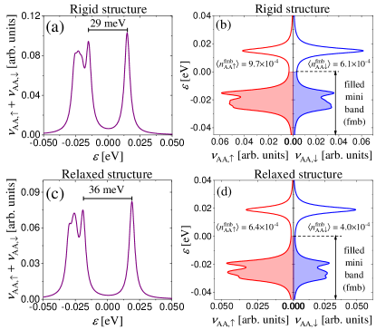
Figure 6(b) depicts the spin up and spin down LDOS at the AA dimer site, denoted as and , respectively, for rigid lattice structure. A clear spin-imbalance is evident between the spin-up and spin-down occupation numbers in the filled miniband (fmb). Quantitatively, the occupation numbers are and . This imbalance translates to a spin polarization at the AA dimer site, corresponding to a local magnetic moment . In Fig. 6(d), which corresponds to the relaxed lattice structure, the occupation numbers are and , with a spin polarization at the AA dimer site.
In summary, the Stoner mechanism is robust against the suppression of the flat-band LDOS peak due to lattice relaxation. The ferromagnetic phase is preserved, but the magnitude of the local magnetic moments becomes smaller than the ones computed for rigid structures.
IV Conclusions
In this work, we investigate the emergence of magnetism in low-angle TBG systems using a numerical real-space approach. We have considered a tight-binding Hamiltonian with a mean-field Hubbard term and obtained the ground state of TBG systems by a self-consistent iteration procedure. Notably, owing to the HHK recursive technique [42, 43, 44, 45], our approach allows calculations to be efficiently performed for very large moiré cells. To validate our method, as detailed in App. A, we compare our results for low-angle TBGs at the CNP with those previously reported in the literature [46]. Specifically, we have found the emergence of an antiferromagnetic phase for low-angle TBGs with a maximum local spin polarization near the magic angle. For all computed twist angles , the agreement of with Ref. [46] is excellent, demonstrating the accuracy of our computational procedure.
The main finding of this study is the emergence of a ferromagnetic phase in low-angle TBGs at -filling of the conduction miniband. Motivated by recent experiments [24, 73] we have investigated the DOS, the local and total magnetization of TBGs for the rotational angle . Our calculations for the case of -filling of the conduction miniband (3 electrons in excess to the CNP per moiré cell) show that the system ground state is a ferromagnetic insulator, in agreement with the experimental findings [24], with a gap of meV. This gap is larger than the one experimentally reported in MATBGs at the charge neutrality point, but one should keep in mind that these are different systems with distinct underlying physics, which may account for the observed discrepancies. We attribute this behavior to the large LDOS at the AA-stacking region, as predicted by the continuum [21, 23] and tight-binding model [19, 74], that causes a strong enhancement of the electron-electron interaction, a key element for the Stoner mechanism. Our method neither challenges the substrate-induced gap proposed in Ref. [25, 26], nor addresses the chiral edge observed in Ref. [24]. Instead, we provide an alternative scenario for the appearance of the ferromagnetic phase, regardless of the substrate alignment, which can serve as a motivation for additional experimental studies.
We expect our methodology to be useful for studying the interaction effects of other moiré 2D systems with large primitive unit cells. For instance, with modest adaptations, our approach can be used in the analysis of anisotropic ferromagnetism dominated by the orbital magnetic moment in 3/4-filling at the conduction miniband of MATBG systems [73]. In addition, the presence of an external magnetic field that typically requires the use of large supercells in standard approaches is trivially accounted for in our method. Finally, an important development of our method for low-angle TBGs is the inclusion of Coulomb interactions between the localized electronic states, which is the next goal we plan to pursue.
Appendix A Magnetism at the CNP
Here, we compare the results obtained using the self-consistent scheme described in Sec. II.3 with those presented in Ref. [46] (that considered rigid structures only). The excellent agreement serves to validate our method.
Figure 7(a) displays the local spin polarization, , within the moiré unit cell for a lattice corresponding to a rotation angle with . The regions with the largest local magnetic moments correspond to those of enhanced LDOS, see Fig. 2, strongly suggesting that the emergence of magnetism can be attributed to the Stoner mechanism [64]. In the AA stacking region, the imbalance between and leads to the emergence of an antiferromagnetic ground state at the CNP, as can be seen in the zoom.
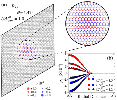
Figure 7(b) shows the local spin polarization for a TBG system with for different values of the on-site Coulomb interaction, , and , as a function of the radial distance to the AA dimer site. Here, the distance between the AA dimer site and the AB nondimer one is Å. In line with Fig. 7(a), one observes that the spin polarization shows a maximum at the AA-stacking region and gradually decreases and eventually vanishes for the sites that are closer to the AB stacking. The magnitude of local spin polarization becomes increasingly larger with increasing on-site Coulomb interaction , and the overall dependence on the radial distance to the AA dimer site is similar for all values considered. Note that since the ground state is antiferromagnetic, the total spin polarization per moiré cell is zero for all values of . Figure 7 shows excellent agreement with the reciprocal space calculation reported in Ref. [46].
Figure 8 displays the LDOS of the flat miniband calculated for AA dimer site, namely, for a twist angle of with . Due to the electron-electron interaction, the LDOS of the flat miniband in the AA dimer site is split into two peaks almost symmetric around the Fermi energy, here set to , and a small gap is opened. The separation between the two LDOS peaks is approximately eV. Note that since the charge density is not homogeneous, one expects to differ from the DOS(). However, since the two low-energy LDOS peaks are absent in the atomic sites at the AB-stacking region, the captures the main features of at low energies.
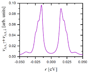
Figure 9(a) shows the maximum spin polarization that corresponds to the AA dimer site, , as a function of the on-site Coulomb repulsion for different twist angles , and . We observe that the local spin polarization at the AA dimer site increases monotonically with increasing . Furthermore, versus shows a similar (almost linear) slope for and , while for both and its slope with respect to are much smaller. This suggests that is close to a critical angle where the magnetic phase ceases to exist. A study of the critical values of for the zero temperature normal antiferromagnetic transition of TBG systems at the CNP can be found in Ref. [46], which estimates the critical values of .
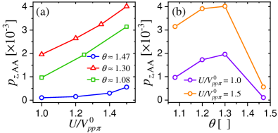
Figure 9(b) shows the maximum spin polarization, , as a function of the magic angle for and . We note that shows a maximum close to for different values of , consistent with Fig. 9(a). This value of is slightly shifted with respect to the magic angle, , which can be attributed to small differences in the corresponding single-particle model Hamiltonian parameterizations.
Acknowledgements.
We thank J. Vahedi for the discussions and for providing the data of his computations of TBG systems. This work was partially supported by the Brazilian Institute of Science and Technology (INCT) in Carbon Nanomaterials and the Brazilian agencies CAPES, CNPq, FAPEMIG, and FAPERJ. ESM acknowledges financial support from ANID Chile Fondecyt 1221301.References
- MacDonald [2019] A. H. MacDonald, Bilayer graphene’s wicked, twisted road, Physics 12, 12 (2019).
- Andrei and MacDonald [2020] E. Andrei and A. MacDonald, Graphene bilayers with a twist, Nat. Mater. 19, 1265–1275 (2020).
- Cao et al. [2018a] Y. Cao, V. Fatemi, A. Demir, S. Fang, S. L. Tomarken, J. Y. Luo, J. D. Sanchez-Yamagishi, K. Watanabe, T. Taniguchi, E. Kaxiras, R. C. Ashoori, and P. Jarillo-Herrero, Correlated insulator behaviour at half-filling in magic-angle graphene superlattices, Nature 556, 80 (2018a).
- Cao et al. [2018b] Y. Cao, V. Fatemi, S. Fang, K. Watanabe, T. Taniguchi, E. Kaxiras, and P. Jarillo-Herrero, Unconventional superconductivity in magic-angle graphene superlattices, Nature 556, 43 (2018b).
- Yankowitz et al. [2019] M. Yankowitz, S. Chen, H. Polshyn, Y. Zhang, K. Watanabe, T. Taniguchi, D. Graf, A. F. Young, and C. R. Dean, Tuning superconductivity in twisted bilayer graphene, Science 363, 1059 (2019).
- Kerelsky et al. [2019] A. Kerelsky, L. J. McGilly, D. M. Kennes, L. Xian, M. Yankowitz, S. Chen, K. Watanabe, T. Taniguchi, J. Hone, C. Dean, A. Rubio, and A. N. Pasupathy, Maximized electron interactions at the magic angle in twisted bilayer graphene, Nature 572, 95 (2019).
- Lu et al. [2019] X. Lu, P. Stepanov, W. Yang, M. Xie, M. A. Aamir, I. Das, C. Urgell, K. Watanabe, T. Taniguchi, G. Zhang, A. Bachtold, A. H. MacDonald, and D. K. Efetov, Superconductors, orbital magnets and correlated states in magic-angle bilayer graphene, Nature 574, 653 (2019).
- Serlin et al. [2020] M. Serlin, C. L. Tschirhart, H. Polshyn, Y. Zhang, J. Zhu, K. Watanabe, T. Taniguchi, L. Balents, and A. F. Young, Intrinsic quantized anomalous Hall effect in a moiré; heterostructure, Science 367, 900 (2020).
- Saito et al. [2021] Y. Saito, F. Yang, J. Ge, X. Liu, T. Taniguchi, K. Watanabe, J. I. A. Li, E. Berg, and A. F. Young, Isospin pomeranchuk effect in twisted bilayer graphene, Nature 592, 220 (2021).
- Utama et al. [2021] M. I. B. Utama, R. J. Koch, K. Lee, N. Leconte, H. Li, S. Zhao, L. Jiang, J. Zhu, K. Watanabe, T. Taniguchi, P. D. Ashby, A. Weber-Bargioni, A. Zettl, C. Jozwiak, J. Jung, E. Rotenberg, A. Bostwick, and F. Wang, Visualization of the flat electronic band in twisted bilayer graphene near the magic angle twist, Nat. Phys. 17, 184 (2021).
- Lisi et al. [2021] S. Lisi, X. Lu, T. Benschop, T. A. de Jong, P. Stepanov, J. R. Duran, F. Margot, I. Cucchi, E. Cappelli, A. Hunter, A. Tamai, V. Kandyba, A. Giampietri, A. Barinov, J. Jobst, V. Stalman, M. Leeuwenhoek, K. Watanabe, T. Taniguchi, L. Rademaker, S. J. van der Molen, M. P. Allan, D. K. Efetov, and F. Baumberger, Observation of flat bands in twisted bilayer graphene, Nat. Phys. 17, 189 (2021).
- Tseng et al. [2022] C.-C. Tseng, X. Ma, Z. Liu, K. Watanabe, T. Taniguchi, J.-H. Chu, and M. Yankowitz, Anomalous Hall effect at half filling in twisted bilayer graphene, Nat. Phys. 18, 1745 (2022).
- Liu et al. [2022] C. Liu, Z. Li, R. Qiao, Q. Wang, Z. Zhang, F. Liu, Z. Zhou, N. Shang, H. Fang, M. Wang, Z. Liu, Z. Feng, Y. Cheng, H. Wu, D. Gong, S. Liu, Z. Zhang, D. Zou, Y. Fu, J. He, H. Hong, M. Wu, P. Gao, P.-H. Tan, X. Wang, D. Yu, E. Wang, Z.-J. Wang, and K. Liu, Designed growth of large bilayer graphene with arbitrary twist angles, Nat. Mater. 21, 1263 (2022).
- Lin et al. [2022] J.-X. Lin, Y.-H. Zhang, E. Morissette, Z. Wang, S. Liu, D. Rhodes, K. Watanabe, T. Taniguchi, J. Hone, and J. I. A. Li, Spin-orbit–driven ferromagnetism at half moiré filling in magic-angle twisted bilayer graphene, Science 375, 437 (2022).
- Jaoui et al. [2022] A. Jaoui, I. Das, G. Di Battista, J. Díez-Mérida, X. Lu, K. Watanabe, T. Taniguchi, H. Ishizuka, L. Levitov, and D. K. Efetov, Quantum critical behaviour in magic-angle twisted bilayer graphene, Nat. Phys. 18, 633 (2022).
- Carr et al. [2017] S. Carr, D. Massatt, S. Fang, P. Cazeaux, M. Luskin, and E. Kaxiras, Twistronics: Manipulating the electronic properties of two-dimensional layered structures through their twist angle, Phys. Rev. B 95, 075420 (2017).
- Wang et al. [2019] J. Wang, X. Mu, L. Wang, and M. Sun, Properties and applications of new superlattice: twisted bilayer graphene, Mater. Today Phys. 9, 100099 (2019).
- Suárez Morell et al. [2010] E. Suárez Morell, J. D. Correa, P. Vargas, M. Pacheco, and Z. Barticevic, Flat bands in slightly twisted bilayer graphene: Tight-binding calculations, Phys. Rev. B 82, 121407 (2010).
- Trambly de Laissardière et al. [2010] G. Trambly de Laissardière, D. Mayou, and L. Magaud, Localization of Dirac electrons in rotated graphene bilayers, Nano Lett. 10, 804 (2010).
- Lopes dos Santos et al. [2007] J. M. B. Lopes dos Santos, N. M. R. Peres, and A. H. Castro Neto, Graphene bilayer with a twist: Electronic structure, Phys. Rev. Lett. 99, 256802 (2007).
- Bistritzer and MacDonald [2011] R. Bistritzer and A. H. MacDonald, Moiré bands in twisted double-layer graphene, Proc. Natl. Acad. Sci. U.S.A. 108, 12233 (2011).
- Lopes dos Santos et al. [2012] J. M. B. Lopes dos Santos, N. M. R. Peres, and A. H. Castro Neto, Continuum model of the twisted graphene bilayer, Phys. Rev. B 86, 155449 (2012).
- Tarnopolsky et al. [2019] G. Tarnopolsky, A. J. Kruchkov, and A. Vishwanath, Origin of magic angles in twisted bilayer graphene, Phys. Rev. Lett. 122, 106405 (2019).
- Sharpe et al. [2019] A. L. Sharpe, E. J. Fox, A. W. Barnard, J. Finney, K. Watanabe, T. Taniguchi, M. A. Kastner, and D. Goldhaber-Gordon, Emergent ferromagnetism near three-quarters filling in twisted bilayer graphene, Science 365, 605 (2019).
- Zhang et al. [2019] Y.-H. Zhang, D. Mao, and T. Senthil, Twisted bilayer graphene aligned with hexagonal boron nitride: Anomalous Hall effect and a lattice model, Phys. Rev. Res. 1, 033126 (2019).
- Bultinck et al. [2020] N. Bultinck, S. Chatterjee, and M. P. Zaletel, Mechanism for anomalous hall ferromagnetism in twisted bilayer graphene, Phys. Rev. Lett. 124, 166601 (2020).
- Yazyev [2010] O. V. Yazyev, Emergence of magnetism in graphene materials and nanostructures, Rep. Prog. Phys. 73, 056501 (2010).
- Fernández-Rossier and Palacios [2007] J. Fernández-Rossier and J. J. Palacios, Magnetism in graphene nanoislands, Phys. Rev. Lett. 99, 177204 (2007).
- Wang et al. [2009] W. L. Wang, O. V. Yazyev, S. Meng, and E. Kaxiras, Topological frustration in graphene nanoflakes: Magnetic order and spin logic devices, Phys. Rev. Lett. 102, 157201 (2009).
- Feldner et al. [2010] H. Feldner, Z. Y. Meng, A. Honecker, D. Cabra, S. Wessel, and F. F. Assaad, Magnetism of finite graphene samples: Mean-field theory compared with exact diagonalization and quantum Monte Carlo simulations, Phys. Rev. B 81, 115416 (2010).
- Fujita et al. [1996] M. Fujita, K. Wakabayashi, K. Nakada, and K. Kusakabe, Peculiar localized state at zigzag graphite edge, J. Phys. Soc. Japan 65, 1920 (1996).
- Son et al. [2006] Y.-W. Son, M. L. Cohen, and S. G. Louie, Energy Gaps in Graphene Nanoribbons, Phys. Rev. Lett. 97, 216803 (2006).
- Fernández-Rossier [2008] J. Fernández-Rossier, Prediction of hidden multiferroic order in graphene zigzag ribbons, Phys. Rev. B 77, 075430 (2008).
- Pisani et al. [2007] L. Pisani, J. A. Chan, B. Montanari, and N. M. Harrison, Electronic structure and magnetic properties of graphitic ribbons, Phys. Rev. B 75, 064418 (2007).
- Tao et al. [2011] C. Tao, L. Jiao, O. V. Yazyev, Y.-C. Chen, J. Feng, X. Zhang, R. B. Capaz, J. M. Tour, A. Zettl, S. G. Louie, H. Dai, and M. F. Crommie, Spatially resolving edge states of chiral graphene nanoribbons,, Nat. Phys. 7, 616 (2011).
- Carvalho et al. [2014] A. R. Carvalho, J. H. Warnes, and C. H. Lewenkopf, Edge magnetization and local density of states in chiral graphene nanoribbons, Phys. Rev. B 89, 245444 (2014).
- Yazyev and Helm [2007] O. V. Yazyev and L. Helm, Defect-induced magnetism in graphene, Phys. Rev. B 75, 125408 (2007).
- Miranda et al. [2016] V. G. Miranda, L. G. G. V. Dias da Silva, and C. H. Lewenkopf, Coulomb charging energy of vacancy-induced states in graphene, Phys. Rev. B 94, 075114 (2016).
- Chen et al. [2011] J.-H. Chen, L. Li, W. G. Cullen, E. D. Williams, and M. S. Fuhrer, Tunable Kondo effect in graphene with defects, Nat. Phys. 7, 535 (2011).
- Miranda et al. [2014] V. G. Miranda, L. G. G. V. Dias da Silva, and C. H. Lewenkopf, Disorder-mediated Kondo effect in graphene, Phys. Rev. B 90, 201101 (2014).
- Jiang et al. [2018] Y. Jiang, P.-W. Lo, D. May, G. Li, G.-Y. Guo, F. B. Anders, T. Tanigushi, K. Watanabe, J. Mao, and E. Y. Andrei, Inducing kondo screening of vacancy magnetic moments in graphene with gating and local curvature, Nat. Commun. 9, 2349 (2018).
- Vidarte and Lewenkopf [2022] K. J. U. Vidarte and C. Lewenkopf, High-energy Landau levels in graphene beyond nearest-neighbor hopping processes: Corrections to the effective Dirac Hamiltonian, Phys. Rev. B 106, 155414 (2022).
- Haydock et al. [1972] R. Haydock, V. Heine, and M. J. Kelly, Electronic structure based on the local atomic environment for tight-binding bands, J. Phys. C: Solid State Phys. 5, 2845 (1972).
- Haydock et al. [1975] R. Haydock, V. Heine, and M. J. Kelly, Electronic structure based on the local atomic environment for tight-binding bands: II, J. Phys. C: Solid State Phys. 8, 2591 (1975).
- Haydock [1980] R. Haydock, Comput. Phys. Commun. 20, 11 (1980).
- Vahedi et al. [2021] J. Vahedi, R. Peters, A. Missaoui, A. Honecker, and G. T. de Laissardière, Magnetism of magic-angle twisted bilayer graphene, SciPost Phys. 11, 083 (2021).
- Rozhkov et al. [2016] A. Rozhkov, A. Sboychakov, A. Rakhmanov, and F. Nori, Electronic properties of graphene-based bilayer systems, Phys. Rep. 648, 1 (2016).
- Katsnelson [2020] M. Katsnelson, The Physics of Graphene (Cambridge University Press, 2020).
- Moon and Koshino [2013] P. Moon and M. Koshino, Optical absorption in twisted bilayer graphene, Phys. Rev. B 87, 205404 (2013).
- Mele [2010] E. J. Mele, Commensuration and interlayer coherence in twisted bilayer graphene, Phys. Rev. B 81, 161405 (2010).
- Mele [2012] E. J. Mele, Interlayer coupling in rotationally faulted multilayer graphenes, J. Phys. D: Appl. Phys. 45, 154004 (2012).
- Yao et al. [2018] W. Yao, E. Wang, C. Bao, Y. Zhang, K. Zhang, K. Bao, C. K. Chan, C. Chen, J. Avila, M. C. Asensio, J. Zhu, and S. Zhou, Quasicrystalline 30∘ twisted bilayer graphene as an incommensurate superlattice with strong interlayer coupling, Proc. Natl. Acad. Sci. U.S.A. 115, 6928 (2018).
- Ahn et al. [2018] S. J. Ahn, P. Moon, T.-H. Kim, H.-W. Kim, H.-C. Shin, E. H. Kim, H. W. Cha, S.-J. Kahng, P. Kim, M. Koshino, Y.-W. Son, C.-W. Yang, and J. R. Ahn, Dirac electrons in a dodecagonal graphene quasicrystal, Science 361, 782 (2018).
- Vidarte and Lewenkopf [2024] K. Vidarte and C. Lewenkopf, Quasicrystalline 30∘ twisted bilayer graphene: Fractal patterns and electronic localization properties, arXiv:2409.05126 (2024).
- Nam and Koshino [2017] N. N. T. Nam and M. Koshino, Lattice relaxation and energy band modulation in twisted bilayer graphene, Phys. Rev. B 96, 075311 (2017).
- Plimpton [1995] S. Plimpton, Fast parallel algorithms for short-range molecular dynamics, J. Comput. Phys. 117, 1 (1995).
- Leven et al. [2014] I. Leven, I. Azuri, L. Kronik, and O. Hod, Inter-layer potential for hexagonal boron nitride, J. Chem. Phys. 140, 104106 (2014).
- Leven et al. [2016] I. Leven, T. Maaravi, I. Azuri, L. Kronik, and O. Hod, Interlayer potential for graphene/h-bn heterostructures, J. Chem. Theory Comput. 12, 2896 (2016).
- Maaravi et al. [2017] T. Maaravi, I. Leven, I. Azuri, L. Kronik, and O. Hod, Interlayer potential for homogeneous graphene and hexagonal boron nitride systems: Reparametrization for many-body dispersion effects, J. Phys. Chem. C 121, 22826 (2017).
- Ouyang et al. [2018] W. Ouyang, D. Mandelli, M. Urbakh, and O. Hod, Nanoserpents: Graphene nanoribbon motion on two-dimensional hexagonal materials, Nano Lett. 18, 6009 (2018).
- Tersoff [1988] J. Tersoff, New empirical approach for the structure and energy of covalent systems, Phys. Rev. B 37, 6991 (1988).
- Kınacı et al. [2012] A. Kınacı, J. B. Haskins, C. Sevik, and T. Çağın, Thermal conductivity of BN-C nanostructures, Phys. Rev. B 86, 115410 (2012).
- Liang et al. [2020] X. Liang, Z. A. H. Goodwin, V. Vitale, F. Corsetti, A. A. Mostofi, and J. Lischner, Effect of bilayer stacking on the atomic and electronic structure of twisted double bilayer graphene, Phys. Rev. B 102, 155146 (2020).
- Auerbach [1998] A. Auerbach, Interacting Electrons and Quantum Magnetism (Springer, New York, 1998).
- Uryu [2004] S. Uryu, Electronic states and quantum transport in double-wall carbon nanotubes, Phys. Rev. B 69, 075402 (2004).
- Hancock et al. [2010] Y. Hancock, A. Uppstu, K. Saloriutta, A. Harju, and M. J. Puska, Generalized tight-binding transport model for graphene nanoribbon-based systems, Phys. Rev. B 81, 245402 (2010).
- Schüler et al. [2013] M. Schüler, M. Rösner, T. O. Wehling, A. I. Lichtenstein, and M. I. Katsnelson, Optimal hubbard models for materials with nonlocal coulomb interactions: Graphene, silicene, and benzene, Phys. Rev. Lett. 111, 036601 (2013).
- Gonzalez-Arraga et al. [2017] L. A. Gonzalez-Arraga, J. L. Lado, F. Guinea, and P. San-Jose, Electrically controllable magnetism in twisted bilayer graphene, Phys. Rev. Lett. 119, 107201 (2017).
- Koshino et al. [2018] M. Koshino, N. F. Q. Yuan, T. Koretsune, M. Ochi, K. Kuroki, and L. Fu, Maximally localized wannier orbitals and the extended hubbard model for twisted bilayer graphene, Phys. Rev. X 8, 031087 (2018).
- Song and Bernevig [2022] Z.-D. Song and B. A. Bernevig, Magic-angle twisted bilayer graphene as a topological heavy fermion problem, Phys. Rev. Lett. 129, 047601 (2022).
- Nguyen et al. [2021] V.-H. Nguyen, D. Paszko, M. Lamparski, B. V. Troeye, V. Meunier, and J.-C. Charlier, Electronic localization in small-angle twisted bilayer graphene, 2D Materials 8, 035046 (2021).
- Nguyen et al. [2022] V. H. Nguyen, T. X. Hoang, and J.-C. Charlier, Electronic properties of twisted multilayer graphene, J. Phys. Mater. 5, 034003 (2022).
- Sharpe et al. [2021] A. L. Sharpe, E. J. Fox, A. W. Barnard, J. Finney, K. Watanabe, T. Taniguchi, M. A. Kastner, and D. Goldhaber-Gordon, Evidence of orbital ferromagnetism in twisted bilayer graphene aligned to hexagonal boron nitride, Nano Lett. 21, 4299 (2021).
- Trambly de Laissardière et al. [2012] G. Trambly de Laissardière, D. Mayou, and L. Magaud, Numerical studies of confined states in rotated bilayers of graphene, Phys. Rev. B 86, 125413 (2012).