Spin vector deviation and the gravitational wave memory effect between two free-falling gyroscopes in the plane wave spacetime
Abstract
In the plane wave spacetime, we find that there will be a precession angle deviation between two free-falling gyroscopes when gravitational waves passed through. This kind of angle deviation is closely related to the well-known standard velocity memory effect. Initial conditions such as the separation velocity or displacement between the two gyroscopes will affect this angle deviation. The evolutions of the angle deviation are calculated for different cases. We find that in some extreme circumstance, the angle deviation’s order of magnitude produced by a rotating compact binary source could be rads. Therefore, this memory effect caused by the gravitational wave is likely to be detected in the future.
I Introduction
After decades of exploration, the gravitational waves from a Binary Black Hole merger was successfully detected in 2016 lasky_detecting_2016 abbott_observation_2016 , which marked the arrival of the era of multi-messenger astronomy.
Gravitational wave memory arises from the non-oscillating components of gravitational waves. The research on memory effect can be traced back to 1974 Zeldovich:1974gvh . Zel’dovich and Polnarev claimed that the distance between a pair of test masses should be changed by gravitational waves. Later studies have shown that gravitational waves can also cause the relative velocity change between the two test masses grishchuk_gravitationalwave_1989 . These early discovered memory effects are now usually considered as ordinary memories, since they are all produced by the final state of the gravitational wave source. In 1991, Christodoulou et al. found that the effective energy radiated in gravitational waves would also produce memory effects, which are generally referred to as nonlinear memory or null memory of gravitational waves christodoulou_nonlinear_1991 wiseman_christodoulous_1991 . Later calculations under PN approximation favata_post-newtonian_2009 blanchet_gravitational_2014 favata_nonlinear_2009 and numerical relativity mitman_computation_2021 favata_gravitational-wave_2010 also support the existence of null memory effect.
The essence of null memory is that the passage of gravitational waves (or ’soft gravitons’) causes a permanent change in space-time, which will generate various observable phenomena, or the manifestation of gravitational memory. At present, a large number of manifestations of gravitational memory have been predicted by theoretical calculation, among which the most classic and most studied is known as displacement memory favata_gravitational-wave_2010 zhang_soft_2017 , which is described as the permanent change of distance between a pair of free-falling test particles after gravitational waves pass through. Other memory effects include velocity memory grishchuk_gravitationalwave_1989 divakarla_first-order_2021 , spin memory pasterski_new_2016 nichols_spin_2017 , center-of-mass memory nichols_center–mass_2018 , gyroscope memory seraj_gyroscopic_2021 and so on. The purpose of this paper is to describe a new manifestation of gravitational memory, which is closely related to the velocity memory effect.
A more profound perspective on these memory effects is the correlation with the symmetry group of asymptotically flat spacetime, the Bondi-Metzner-Sachs group flanagan_conserved_2017 sachs_asymptotic_1962 . strominger et al. used an infrared triangle to elaborate the corresponding relationship between memory effects and the soft theorem and the symmetries of null infinity strominger_gravitational_2016 strominger_lectures_2018 . In recent years, numerous studies on BMS groups and their extensions have linked various memory effects to various asymptotic conserved charges nichols_spin_2017 strominger_lectures_2018 seraj_precession_2022 mao_more_2019 . These insights into gravity symmetry may open the way to the quantization of gravity.
We shall work in nonlinear plane gravitational wave spacetimes although the memory effects are frequently studied in asymptotically flat spacetimes. As a local approximation of gravitational waves far from the source, plane waves retain most of the local properties of gravitational waves and are formally easier to calculate. The main research objects in this paper are a pair of separate test gyroscopes, which are placed far away from the source and their back reaction to gravitational waves is negligible. By a natural way of comparing two separated gyroscopes, we express the deviation of the two gyroscopes as an angle, and this angle deviation is a motion independent invariant in flat spacetime. Through direct calculation, we prove that gravitational waves will permanently change the angle deviation between the two gyroscopes, that is, the gravitational memory effects. Remarkably, in plane gravitational wave spacetimes, the angle deviation between gyroscopes naturally corresponds to the velocity memory effect. This peculiarity may motivate some novel proposal for detecting gravitational memory. Moreover, as a by-product of our calculation process, we will discuss the dynamics of a single gyroscope in nonlinear plane wave spacetime and compare it to the known gyroscopic memory in asymptotic flat spacetime seraj_precession_2022 , which might be helpful to delimit the applicable scope of plane gravitational waves.
The paper is organized as follows: Section II reviews the generally formalism for exact plane gravitational wave spacetimes, and the geodesic motion and memory effect in it. In Section III, we first describe the kinematics of gyroscopes in plane wave spacetime, and then we give the precession equations of the free-falling gyroscope with respect to a local tetrad, and describe the differences from the results in asymptotically flat spacetime. Next, We turn to discuss two separated gyroscopes. After illustrating how two observers at different locations with different speeds can compare the gyroscopes they carry, we display the permanent angle deviation between the two gyroscopes generating by gravitational waves. At the end of Section III, we discuss the effects of separation distance and separation velocity on the deviation Angle respectively under a toy model. Finally, in Section IV, we estimate the amplitude of angle deviation generated by compact binary gravitational wave sources.
Notation: Throughout this paper, we use geometric units in which . Greek letters denote the spacetime indices and the range of available values is , Latin indices denote the coordinates indices of the plane of vibration, and the available values is . Hatted letters are internal Lorentz indices associated with a local frame established in section III.1. Capital bold letters represent vectors or matrices and will be explained again after it appears. All the dots above the letters in this paper represent the derivative of unless otherwise stated.
II Exact plane gravitational wave Spacetimes
This section briefly reviews the general plane-wave spacetime metric and its geodesic motion and memory effects.
II.1 Metric
Plane gravitational wave spacetime is commonly described in BJR (Baldwin-Jeffery-Rosen) coordinates and Brinkmann coordinateszhang_soft_2017 harte_optics_2015 . The general form of metric in BJR coordinates is
| (1) |
where the matrix with component are symmetric and positive. In this form, the familiar linearized transverse traceless (TT) gauge can be expressed as , zhang_soft_2017 shows that the BJR coordinates have coordinate singularities, which is typically not global, while the Brinkmann coordinates are the global coordinates of plane wave spacetime, and the metric is written as
| (2) |
where D is a scalar function of with the form of
| (3) |
where and are the amplitude of the and polarization state, the non-zero components of the Riemann curvature tensor are , and the only non-vanishing components of Ricci tensor is . Therefore, when K is traceless, the metric in Brinkmann coordinates strictly satisfies the vacuum Einstein field equation, that is, the space-time is Ricci flat.
There is a conversion relationship between the two coordinates (1) and (2), which can be expressed as
| (4) |
where bold and represents column vectors composed of two coordinates of the plane of vibration, and all the other bold-types represent the 22 matrix. Note that to get an explicit coordinate transformation you still have to solve a second-order ODE of , which is . But many interesting properties can still be analyzed using the above form zhang_soft_2017 . Since has one extra degree of freedom, the coordinate transformation is not a one-to-one mapping if the initial value of is not chosen harte_optics_2015 .
In fact, the Brinkmann coordinate (2) can be thought as a local Lorentz frame of plane wave spacetime divakarla_first-order_2021 , which makes the geodesic equation to some extent equivalent to the observation effect of the origin observer. Therefore, unlike the BJR coordinates, the geodesic motion under the Brinkmann coordinates shows the abundant observation effect of gravitational waves. Moreover, Brinkmann coordinates also have computational advantages over BJR coordinates.
The following calculation in this paper will be mainly use Brinkmann coordinates. The general geodesic motion in Brinkmann coordinates will be reviewed below.
II.2 General geodesic motion
We will briefly rewrite the general solutions of geodesic equation given by flanagan_persistent_2020 , but in a more concise form. first we consider an arbitrary geodesic with tangent vector , the geodesic equation for coordinate is given by
| (5) |
with initial value the general solution can be written as
| (6) |
where the parameter is a conserved constant along the geodesic (). If we use to represent the normal vector of the null hypersurface parameterized by , then . Since there is a linear relationship between and , we will use the coordinate instead of the geodesic affine parameter in the rest of the paper. Then, the geodesic equations of the remaining three coordinates were written as follows:
| (7) |
| (8) |
Hereafter the dot denotes the derivative with respect to . After setting the initial value of position as , and the initial 4-velocity as , the general solution is then obtained as 111Note that solution (9)(10) is only a formal solution, because (11) is still an unavoidable Sturm-Liouville problem about second-order ODE zhang_sturm-liouville_2018 .
| (9) |
| (10) |
where and are both matrices and they satisfy the following equations respectively
| (11) |
with the boundary conditions , . It is obviously that does not appear in the general solution (9) (10), since it is just cleverly hidden in the constant . This also means that in the Brinkmann coordinate, the velocity of the gravitational wave propagation direction has no effect on the motion of the vibration plane. So without losing generality, the following discussions will not consider the velocity of propagation direction, but only the two-dimensional motion of the vibration plane.
By the solution (9) (10) we can easily write the 4-velocity for general geodesic motion as
| (12) |
where
| (13) |
Thanks to the properties of local Lorentz gauge, the geodesic equation (5)(7)(8) in Brinkmann coordinates has the same form as the geodesic deviation equation for the central geodesic, thus the solution (6)(9)(10) is also the solution of the geodesic deviation equation. which makes it convenient for us to give the expressions of displacement memory and velocity memory. Before that, let us briefly review the memory effect in plane wave spacetime.
II.3 Memory effect
We follow the common analytical methods, consider sandwich waves, that is, gravitational waves exist only for a zone like , while the space-time of and are flat but not equivalent. The theoretical foundation of non-equivalence lies in the fact that the flat condition does not constrain the linear evolutionary process, or only shows . In linear theory, it can be expressed as
| (14) |
where and are constants. Of course, this only shows that the space-time before and after the zone can be theoretically unequal. By using the Hamilton-Jacobi method in BJR coordinates, it shows that the space-time before and after the gravitational waves zone are indeed not equivalent zhang_soft_2017 . In short, if we set , we can get
| (15) |
at the linear level. This is the physical reality of the gravitational wave memory effect. The space-time have changed permanently after the pulse passed. This inequivalence of flat space-time will be discussed again in Section III.
Consider a static test particle with initial coordinates and using the solutions (9) of the geodesic equations, the change in position after the passage of a gravitational wave can be written as
| (16) |
which is a general form of displacement memory in our notation. There is more information about velocity memory, since the initial position and the initial velocity can be both taken into account simultaneously. The change of velocity can also be written as
| (17) |
which is a general form of velocity memory in our notation. See the previous section (11) for the definitions of matrix and .
Of course, the manifestations of memory effect are far more than the above two. Looking for more manifestations of memory effect will provide additional possible methods for detecting gravitational waves. In section III, we will try to find a new memory effect by studying the separated spin vectors.
III Spin vectors precession deviation
This section focuses on the possible effects of the evolution of the spin vector in a general plane wave spacetime. The first step is to construct a local tetrad so that we can study the spin vector evolution in a three-dimensional framework. In this framework, we first discuss the precession of a free-falling gyroscope with respect to its own internal tetrad. After that, the method of comparing two separated gyroscopes is described, which is then used to study the precession difference between the separate gyroscopes due to gravitational waves, and finally our results are discussed under a simple gravitational wave model.
III.1 Spin vector evolution of gyroscopes
Consider an observer with four-velocity carries a gyroscope and falls freely, the gyroscopic spin vector obeys Fermi-Walker transport , and always satisfy . If we construct a local tetrad of the observer by making , and . then the spin vector is purely spatial in the tetrad, and the precession equation of the three spatial components can be deduced as seraj_gyroscopic_2021
| (18) |
where is the spin connection one-form associated with the tetrad , and can be consider as a two-form of angular velocity222The antisymmetric tensor can be dualized into a vector , then the precession equation (18) can read as . To calculate , we need to build a local tetrad for any time-like observer in a plane wave spacetime. The four-velocity in Brinkmann coordinates (2) can be generally written as333Because we are working in coordinates, so here does not represent the three-dimensional velocity. The four-velocity that includes three-dimensional velocities should be set as , which is more reasonable but the calculation will be more complicated. According to our analysis in Section 2, the velocity in the propagation direction does not affect the motion of the plane of vibration, so without considering the velocity in the propagation direction, that is, , then can be regarded as the two-dimensional velocity. Still writing instead of -1 here is just to keep generality.
| (19) |
First we let , then subtract the part parallel to with to get . Since the vector is tangent to outgoing null rays, is aligned with the propagation direction of gravitational waves. And finally we use the Gram-Schmidt orthogonalization procedure to get . The whole tetrad is
| (20) | ||||
III.2 Free falling observer
Now let’s consider the gyroscope precession that a free-falling observer carrying a gyroscope might observe. Recall that the precession angular velocity (22) with respect to the local tetrad (20), by substituting the four-velocity of general geodesic motion (12), we get (For a more detailed calculation, see Appendix V). It then follows from (18) that
| (23) |
Accordingly, the spin vector component associated with the local tetrad (20) remains unchanged, which means that a free-falling observer with a gyroscope cannot detect the gravitational waves by observing the precession of the gyroscope.
As we known that the displacement and velocity memory effects are in the order of , where denotes the distance to the source. However, the precession for the spin memory is associated with high order terms, see seraj_precession_2022 herrera_influence_2000 and also pasterski_new_2016 , in which it shows that the leading order of the precession of gyroscopes is in the order of . This spin effect could be also generated by the superrotation charges nichols_spin_2017 or considered as a vacuum transition under the residual Lorentz symmetry godazgar_gravitational_2022 . In our case, there is no similar charge or symmetry, so we keep the order of in the following calculations. Actually, for the known gravitational wave memory effect of order , such as displacement memory and velocity memory, the conclusion of plane wave space-time coincides with that of asymptotically flat spacetime zhang_soft_2017 . Actually, as a local approximation of large , the plane gravitational wave loses some information about the non-linear general gravitational wave, see flanagan_observer_2016 for an example.
In a asymptotically flat spacetime, a static observer means he/she is static relative to the source, and he/she will observe a velocity precession of leading order , which contains the same information as the standard displacement memory. In a plane wave spacetime, we consider a static observer that he/she is static relative to the origin of coordinates, the results are consistent with those in asymptotically flat spacetime (See the calculation in the appendix V ). However, this velocity precession is due to non-vanishing acceleration, and the realistic counterpart of this acceleration is not clear, so we are not going to discuss this case but only leave the results in the appendix V for completeness.
We now turn to the focus on a pair of separated gyroscopes and it will show that gravitational waves create a permanent deviation among them. At the beginning, it is necessary to specify how two observers at different locations with different speeds can compare the gyroscopes that they carry. Since gyroscope spin vectors are spatial for self-observer, considering that parallel transport or Poincare transformation will change the spatiality, we want a comparison method that maintains spatiality, that is, the comparison between spatial vector and spatial vector, so that the deviation angle can be directly calculated. A natural idea is to move them together and have the same velocity, or to make them geodesics overlap, so that the spin vectors can be compared in the same local tetrad. But how to specify the routes to coincide is not easy for a general spacetime. In a flat spacetime, the route is simple and it can be arbitrary. We will show by a very brief calculation that the precession generated by acceleration in a flat spacetime is path-independent.
III.3 Path-independent precession angle
Consider a worldline in a Minkowski space-time, make the acceleration section in , and we do not specify the acceleration, simply write the boundary conditions as
| (24) |
In the Minkowski spacetime, the tetrad and the angular velocity is simply a special case of (20) and (22). By taking , the non-zero angular velocity reads
| (25) |
The components of the angular velocity implies the plane of rotation. Without losing generality, we only consider the acceleration in the direction, then the rotation angle in the plane is obtained by integrating the angular velocity over the interval:
| (26) |
It shows that the precession angle is path-independent, depending only on the starting and ending velocity. Given this property, it is clear how two observers with different speeds on different positions can compare the gyroscopes they carry. All it takes is for them to come together. Or to put it more precisely, make their worldlines overlap, and then we can compare them in the same tetrad. Clearly, this method is very easy to apply in realistic scenarios. More generally, without deflection caused by force, the angle deviation of two gyroscopes is invariant as long as the spacetime remains flat no matter how they move. While the situation in a curved spacetime is much more complicated. For the method of how to compare the spin vectors in different positions in curved spacetime, one can refer to the affine transport method given by flanagan_observer_2016 .
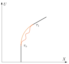
III.4 Permanent angle deviation by separation

In Figure 2, there are two gyroscopes G0 and G1 separated in a distance, in which G0 is placed at the origin and G1 is placed at . Furthermore, their rotation direction is aligned at the beginning and then move along their geodesics respectively until the gravitational wave passes through. Eq. (23) indicates that the spin vector component in the local tetrad remains unchanged. However, the local tetrad of G1 is no longer aligned with G0 because of the velocity memory effect. To compare the spin vectors of the two gyroscopes, their worldlines should be overlapped in our method. One of the natural choices is to accelerate G0 to the same velocity of G1 as follows. Firstly, accelerate G0 to in the direction and then to in the direction, where denotes the velocity memory of G1 relative to G0 in the direction. According to Eq. (26), the precession angle of G0 in the plane is calculated as
| (27) |
In fact, Eq. (27) is the relative precession angle deviation between two separated gyroscopes, since G1 and G0 are both in the same tetrad and their precession angles are zero and respectively. As discussed before, without deflection caused by a force, the angle deviation of two gyroscopes is invariant as long as the spacetime remains flat no matter how they move. So this angle will always exist after the wave passes through. This is the memory effect of two separated spin vectors.
Since the angle deviation (27) contains only the velocity memory , it contains the same information as that of the standard velocity memory. Thus, the precession deviation between two separate spin vectors is just a pattern of manifestation of the velocity memory. Note that it is only true for plane wave spacetime, the deviation of two separated spin vectors in general gravitational waves spacetime still needs further researches. The trick here is that the standard velocity memory may be covered by the acceleration caused by various forces, but the precession deviation is a quantity that is independent of the acceleration. It may be possible to use this to statically observe the velocity memory effect.
III.5 Only the initial separation displacement
In this subsection, we will discuss the precession deviation with initial separation displacement, and in next subsection the initial separation velocity will be considered. Suppose that a detector consists of two gyroscopes and can compare the angle deviation in real time. A reasonable consideration is that there is only initial separation displacement between the two gyroscopes. Consider the simplest case, assuming that the initial separation is only in the direction and the separation distance is . Since the initial separation speed is zero, constant . The gravitational wave region is given by . By using (17), and in linear theory with the transverse traceless gauge, we obtain the angle deviation at time from (27) as the following
| (28) |
whose matrix form is represented below to avoid confusion,
| (29) |
It is shown that the angle deviation is approximately proportional to the initial separation distance L in this case. Actually, the angle deviation at any time in the region of could be given by
| (30) |
which we called the evolution equation of the angle deviation in the gravitational wave region in the simplest case.
To see the evolution of the deviation angle, we calculate it in a toy model of the gravitational collapsezhang_soft_2017 , in which
| (31) |
The comparison between a linear approximation and our numerical results are shown Figure 3.

It shows that there is no final angle deviation for the linear approximation without any leading order velocity memory, while the numerical simulation shows that there is indeed a angle deviation when higher order terms are taken account.
III.6 Initial separation velocity
Now we still consider a detector consisting of two gyroscopes, but with only initial separation velocity. The gyroscopes are all moving along their geodesics, and we also use our method to compare the angle deviation between them in real time. We assume that both gyroscopes G0 and G1 are at the origin at the beginning and G1 has the initial relative velocity along the direction. The final velocity of G1 after the gravitational wave passes through can be readily found from (17) that
| (32) |
in which we have used
| (33) |
We also make G0 catch up with G1 to get the final angle deviation. By performing the same calculation as (30), one can eventually finds that
| (34) |
where . It can be seen that the angle deviation is proportional to the initial separation velocity at the leading order. We repeat the procedure of the previous section, first replacing with to estimate the angle deviation at anytime, and then calculate the linear approximation and numerical results using the simple model (31). The evolution of are shown in Figure 4.

For a general case, in which there are both initial separation displacement and velocity. From the Eq.(13), one can see that the final velocity has a linear relationship with the initial separation displacement and velocity. Thus, the final angle deviation at the linear level is the simple addition of (28) and (34), yielding
| (35) |
IV Angle deviation from compact binary sources
In this section, we specifically estimate the magnitude of angle deviation memory from compact binary sources (CBS). The leading-order memory waveform from CBS in the PN approximation is given bynichols_spin_2017
| (36) |
where M is the total mass of the binary and , , where is the orbital frequency and are the masses of two components. The initial separation of two separated gyroscopes is assumed in the same direction as the + polarization direction. Restoring our results (35) to the standard unit yields
| (37) |
where denotes speed of light. Since the memory term of CBS disappear, the leading order term in Eq.(35) only contains the initial separation velocity , and the contribution from initial separation distance is hidden in the higher order terms. Firstly, it should be noticed that there is a limitation of the plane wave approximation on the initial separation velocity. By using to represent the maximum separation length that allowed by the plane wave approximation and denotes the gravitational wave duration. Then the limitation of the initial separation velocity is , or else the plane wave approximation will be invalid. According to the estimation in divakarla_first-order_2021 , is about meters in the case of . If we assume two gyroscopes have initial separation velocity closed to the speed of light, then the maximum angle deviation between two gyroscopes is estimated about rads. In such an extreme case, it requires a very short duration of gravitational waves. For instance, two super black holes merge will emit a GW memory burst with amplitude boersma_forecasts_2020 .
V Discussion
In this paper, we investigated the precession angle deviation between two separated free-falling gyroscopes in non-linear plane wave spacetime. We first show that in a general plane-wave spacetime a free-falling gyroscopes maintaining its orientation with respect to a local tetrad (20) does not give the same results with that in the asymptotically flat spacetime seraj_gyroscopic_2021 . We then turn to discuss two separated gyroscopes. After illustrating how to compare the local observations of two gyroscopes in a flat spacetime, we find that gravitational waves will generate a permanent angle deviation between the two gyroscopes, and this kind of deviation is another manifestation of the well-known standard velocity memory effect. For compact binary gravitational wave sources, we expect to generate an angle deviation of about rads between two gyroscopes under the most demanding conditions.
The guiding implications of our results for gravitational wave detection warrant further discussion. What we consider here is that two gyroscopes move along their geodesics in the gravitational wave region, and then accelerate them arbitrarily after the wave passes through to make them relatively static. For real situations such as two separated gyroscopes placed on the ground-based detectors. For example, the test masses (mirrors) are replaced by the test gyroscopes in the detectors like LIGO and Virgo, and the detector’s control system will counteract the velocity memory and then leave a permanent angle deviation between the test gyroscopes. Another way to detect such effects is to let the acceleration process occur in the gravitational wave region. For example, two gyroscopes connected by a straight rod without complicated detector control system must have experienced non-trivial acceleration processes in the gravitational wave region to remain relatively static after the wave passed through. We will leave it to our next work.
It would be instructive to conceive of a large Sagnac interferometer sun_sagnac_1996 , which is comparable in size and technique to LIGO. Based on the strain distance now accessible to LIGO, a large Sagnac interferometer might be able to sense the radian change of rad. But given the limitations of ground-based detection, it seems more promising to resort to space-based gravitational-wave detector, such as the future LISA amaro-seoane_laser_2017 , which could be configured as a Sagnac interferometer shaddock_operating_2004 . If such interferometers are placed at different locations in space and try to compare the strain differences accumulated during the passage of gravitational waves, then it is possible to observe this memory effect.
Acknowledgements.
This work is supported by National Science Foundation of China grant No. 11105091.Appendix A For a free-falling observer
Given the metric:
| (38) |
where
| (39) |
all non-zero components of affine connections and the curvature tensor are :
| (40) |
The proper velocity is given by
| (41) |
Establish a local tetrad as
| (42) | ||||
Since the geodesic equation of is , and . We firstly expand the spin connection , yielding
| (43) |
Then by using the tetrad, we obtain
| (44) | ||||
Given the geodesic equation for :
| (45) |
the only non-zero component is
| (46) |
Appendix B For a relatively static observer
In the Brinkmann coordinate, the four-velocity that relative static to the origin reads , after the same calculation we have the tetrad:
| (47) | ||||
spin connection
| (48) |
and the angular velocity 2-form:
| (49) |
The the precession angle is
| (50) |
which is actually generated by non-vanishing acceleration, and the four-acceleration is
| (51) |
or
| (52) |
References
- (1) P. D. Lasky, E. Thrane, Y. Levin, J. Blackman, and Y. Chen, “Detecting gravitational-wave memory with LIGO: Implications of GW150914,”. https://www.webofscience.com/wos/woscc/summary/1eb95eb2-2242-49e1-8dcb-e1f3b85519a4-49a3c6b7/date-descending/1. Place: College Pk Publisher: Amer Physical Soc WOS:000381442800002.
- (2) B. Abbott, R. Abbott, T. Abbott, M. Abernathy, et al., “Observation of gravitational waves from a binary black hole merger,”. https://link.aps.org/doi/10.1103/PhysRevLett.116.061102.
- (3) Y. B. Zel’dovich and A. G. Polnarev, “Radiation of gravitational waves by a cluster of superdense stars,” Sov. Astron. 18 (1974) 17.
- (4) L. P. Grishchuk and A. G. Polnarev, “Gravitationalwave pulseswith ”velocity-coded memory”,”.
- (5) D. Christodoulou, “Nonlinear nature of gravitation and gravitational-wave experiments,”. https://link.aps.org/doi/10.1103/PhysRevLett.67.1486.
- (6) A. G. Wiseman and C. M. Will, “Christodoulou’s nonlinear gravitational-wave memory: Evaluation in the quadrupole approximation,”. https://link.aps.org/doi/10.1103/PhysRevD.44.R2945.
- (7) M. Favata, “Post-newtonian corrections to the gravitational-wave memory for quasicircular, inspiralling compact binaries,” 0812.0069 [astro-ph, physics:gr-qc]. http://arxiv.org/abs/0812.0069.
- (8) L. Blanchet, “Gravitational radiation from post-newtonian sources and inspiralling compact binaries,”. http://link.springer.com/10.12942/lrr-2014-2.
- (9) M. Favata, “NONLINEAR GRAVITATIONAL-WAVE MEMORY FROM BINARY BLACK HOLE MERGERS,”. https://iopscience.iop.org/article/10.1088/0004-637X/696/2/L159.
- (10) K. Mitman, J. Moxon, M. A. Scheel, S. A. Teukolsky, M. Boyle, N. Deppe, L. E. Kidder, and W. Throwe, “Computation of displacement and spin gravitational memory in numerical relativity.” http://arxiv.org/abs/2007.11562.
- (11) M. Favata, “The gravitational-wave memory effect,”. https://www.webofscience.com/wos/woscc/summary/1eb95eb2-2242-49e1-8dcb-e1f3b85519a4-49a3c6b7/date-descending/1. Place: Bristol Publisher: Iop Publishing Ltd WOS:000282154300037.
- (12) P.-M. Zhang, C. Duval, G. W. Gibbons, and P. A. Horvathy, “Soft gravitons & the memory effect for plane gravitational waves,” 1705.01378 [astro-ph, physics:gr-qc, physics:hep-th]. http://arxiv.org/abs/1705.01378.
- (13) A. K. Divakarla and B. F. Whiting, “The first-order velocity memory effect from compact binary coalescing sources,” 2106.05163 [gr-qc]. http://arxiv.org/abs/2106.05163.
- (14) S. Pasterski, A. Strominger, and A. Zhiboedov, “New gravitational memories,”. https://www.webofscience.com/wos/woscc/summary/1eb95eb2-2242-49e1-8dcb-e1f3b85519a4-49a3c6b7/date-descending/1. Place: New York Publisher: Springer WOS:000399289900003.
- (15) D. A. Nichols, “Spin memory effect for compact binaries in the post-newtonian approximation,”. https://www.webofscience.com/wos/woscc/summary/1eb95eb2-2242-49e1-8dcb-e1f3b85519a4-49a3c6b7/date-descending/1. Place: College Pk Publisher: Amer Physical Soc WOS:000400143100003.
- (16) D. A. Nichols, “Center-of-mass angular momentum and memory effect in asymptotically flat spacetimes,”. https://www.webofscience.com/wos/woscc/summary/1eb95eb2-2242-49e1-8dcb-e1f3b85519a4-49a3c6b7/date-descending/1. Place: College Pk Publisher: Amer Physical Soc WOS:000444778500004.
- (17) A. Seraj and B. Oblak, “Gyroscopic gravitational memory.” http://arxiv.org/abs/2112.04535.
- (18) E. E. Flanagan and D. A. Nichols, “Conserved charges of the extended bondi-metzner-sachs algebra,” 1510.03386 [gr-qc, physics:hep-th]. http://arxiv.org/abs/1510.03386.
- (19) R. Sachs, “Asymptotic symmetries in gravitational theory,”. https://link.aps.org/doi/10.1103/PhysRev.128.2851.
- (20) A. Strominger and A. Zhiboedov, “Gravitational memory, BMS supertranslations and soft theorems,”. https://www.webofscience.com/wos/woscc/summary/1eb95eb2-2242-49e1-8dcb-e1f3b85519a4-49a3c6b7/date-descending/1. Place: New York Publisher: Springer WOS:000368178500001.
- (21) A. Strominger, “Lectures on the infrared structure of gravity and gauge theory.” http://arxiv.org/abs/1703.05448.
- (22) A. Seraj and B. Oblak, “The precession caused by gravitational waves,” 2203.16216 [gr-qc, physics:hep-th]. http://arxiv.org/abs/2203.16216.
- (23) P. Mao and X. Wu, “More on gravitational memory,”. https://www.webofscience.com/wos/woscc/summary/1eb95eb2-2242-49e1-8dcb-e1f3b85519a4-49a3c6b7/date-descending/1. Place: New York Publisher: Springer WOS:000467630200001.
- (24) A. I. Harte, “Optics in a nonlinear gravitational plane wave.” http://arxiv.org/abs/1502.03658.
- (25) E. E. Flanagan, A. M. Grant, A. I. Harte, and D. A. Nichols, “Persistent gravitational wave observables: Nonlinear plane wave spacetimes,”. https://link.aps.org/doi/10.1103/PhysRevD.101.104033.
- (26) P.-M. Zhang, M. Elbistan, G. W. Gibbons, and P. A. Horvathy, “Sturm-liouville and carroll: at the heart of the memory effect,” 1803.09640 [gr-qc, physics:hep-th, physics:math-ph]. http://arxiv.org/abs/1803.09640.
- (27) L. Herrera and J. L. H. Pastora, “On the influence of gravitational radiation on a gyroscope,”. https://iopscience.iop.org/article/10.1088/0264-9381/17/18/302.
- (28) M. Godazgar, G. Long, and A. Seraj, “Gravitational memory effects and higher derivative actions.” http://arxiv.org/abs/2206.12339.
- (29) E. E. Flanagan and D. A. Nichols, “Observer dependence of angular momentum in general relativity and its relationship to the gravitational-wave memory effect.” http://arxiv.org/abs/1411.4599.
- (30) O. M. Boersma, D. A. Nichols, and P. Schmidt, “Forecasts for detecting the gravitational-wave memory effect with advanced LIGO and virgo,”. https://www.webofscience.com/wos/woscc/summary/1eb95eb2-2242-49e1-8dcb-e1f3b85519a4-49a3c6b7/date-descending/1. Place: College Pk Publisher: Amer Physical Soc WOS:000527519500003.
- (31) K.-X. Sun, M. M. Fejer, E. Gustafson, and R. L. Byer, “Sagnac interferometer for gravitational-wave detection,”. https://link.aps.org/doi/10.1103/PhysRevLett.76.3053.
- (32) P. Amaro-Seoane, H. Audley, S. Babak, et al., “Laser interferometer space antenna.” http://arxiv.org/abs/1702.00786.
- (33) D. A. Shaddock, “Operating LISA as a sagnac interferometer,”. https://link.aps.org/doi/10.1103/PhysRevD.69.022001.