Spin-Phonon-Photon Strong Coupling in a Piezoelectric Nanocavity
Abstract
We introduce a hybrid tripartite quantum system for strong coupling between a semiconductor spin, a mechanical phonon, and a microwave photon. Consisting of a piezoelectric resonator with an integrated diamond strain concentrator, this system achieves microwave-acoustic and spin-acoustic coupling rates MHz or greater, allowing for simultaneous ultra-high cooperativities ( and , respectively). From finite-element modeling and master equation simulations, we estimate photon-to-spin quantum state transfer fidelities exceeding 0.97 based on separately demonstrated device parameters. We anticipate that this device will enable hybrid quantum architectures that leverage the advantages of both superconducting circuits and solid-state spins for information processing, memory, and networking.
Solid-state quantum systems based on superconductors and spins are leading platforms that offer complementary advantages in quantum computing and networking. Superconducting quantum processors enable fast and high-fidelity entangling gates [1, 2], but challenges remain in quantum memory time and long-distance networking. Conversely, atom-like emitters in solid-state have demonstrated long spin coherence time, efficient spin-photon interfaces for long-distance entanglement, and high readout fidelity [3, 4, 5, 6, 7, 8]. Coupling these modalities is therefore an exciting direction in quantum information science.
Previous studies using magnetic coupling between microwave (MW) photons and spins have been limited to multi-spin ensemble interactions [9, 10, 11, 12, 13, 14, 15] due to low spin-magnetic susceptibility and the low magnetic energy density of MW resonators [16, 17, 18]. Alternate experiments and proposals rely on coupling via intermediate acoustic modes [19, 20, 21], which have experimentally demonstrated large coupling to superconducting circuits [22, 23, 24, 25, 26] and are predicted to have large coupling to diamond quantum emitters [27, 28, 29, 30, 31, 32, 33]. However, designing a device that strongly couples one phonon to both one MW photon and to one spin – enabling an efficient MW photon-to-spin interface – remains an outstanding challenge.
Here we address this problem through the co-design of a scandium-doped aluminum nitride (ScAlN) Lamb wave resonator with a heterogeneously-integrated diamond thin film. This structure piezoelectrically couples a MW photon and acoustic phonon while concentrating strain at the location of a diamond quantum emitter. Through finite-element modeling, we predict photon-phonon coupling MHz concurrent with phonon-spin coupling MHz. These rates yield photon-phonon and phonon-spin cooperativities of order assuming demonstrated lifetimes of spins, mechanical resonators, and superconducting circuits [34, 35]. We explore state transfer protocols via quantum master equation (QME) simulations and show that this device can achieve photon-to-spin transduction fidelity with conservative hardware parameters. We find that performance of these schemes is likely limited by two-level system (TLS) loss in current piezoelectrics. An improvement in piezoelectric TLS loss rates to that of silicon will pave the way towards SC-spin state transduction with .
We consider a coupled tripartite system consisting of a superconducting circuit (SC), acoustic phonon, and Group-IV electron spin with the Hamiltonian (see [36] for detailed derivation)
| (3) |

Here, the SC frequency is defined by the transmon Josephson and shunt capacitances, the spin frequency is given by the Zeeman splitting of the electron spin states, and the acoustic frequency is defined by the acoustic resonator geometry. The first three terms of this equation describe the energies of the uncoupled modes of the devices (Fig. 1(a-c)) while the fourth and fifth terms describe the interaction dynamics. Generally, SCs feature GHz [37]. Electron spin resonant frequencies can be arbitrarily set by an external magnetic field; to match this frequency range, fields T are required [38]. The coupling coefficient is physically governed by the piezoelectric effect, whereby a strain field produces an electric response and vice versa (Fig. 1(d)). This interaction is described by the strain-charge equations
| (4) | ||||
| (5) |
where and are the elastic and piezoelectric coefficient tensors of the resonator’s piezoelectric material, and are the stress and strain fields, and and are the electric and displacement fields. At single quantum levels, a MW photon in the SC will generate an electric field in the volume of the piezoelectric resonator described by
| (6) |
where is the electric field profile of the IDT for an arbitrary applied voltage , and the capacitances are indicated in Fig. 1. Since is typically much larger than and for transmon qubit configurations, the MW photon energy is largely contained in the shunt capacitor. Similarly, a phonon in the piezoelectric resonator will produce a strain field described by
| (7) |
where is the strain profile of the acoustic mode for an arbitrary mechanical displacement. Following (5), will produce an electric displacement field given by , where d is the piezoelectric coefficient tensor. Then the coupling will be determined by the overlap integral between and [39],
| (8) |

The spin-phonon coupling results from the spin-strain susceptibility of quantum emitters in a strain field [38, 40, 41]. For a single-phonon strain profile , the resulting coupling is . In Group IV emitters in diamond, depends heavily on the spin-orbit mixing enabled by an off-axis magnetic field (see [36]) and primarily interacts with transverse strain in the emitter frame [38]. Therefore, for the rest of this analysis, we set this expression to be
| (9) |
where is the single-phonon strain profile in the coordinate system of the emitter and PHz/strain [41].
To implement the device in Fig.1, we require a platform with (i) superconductivity, (ii) piezoelectricity, (iii) acoustic cavities, and (iv) strain transfer to diamond emitters. To address (i-ii), we propose a silicon-on-insulator (SOI) platform with a thin-film deposition of scandium-doped aluminum nitride (ScAlN). This material system allows for superconducting qubits and piezoelectrics to co-inhabit one chip [42, 43]. To answer (iii-iv), we co-design a Nb-on-Sc0.32Al0.68N-on-SOI piezoelectric resonator with a heterogeneously integrated diamond thin membrane. We propose Niobium (Nb) as a well-characterized superconductor with high T and T [44, 45, 46], as required for operation with the spin. SOI platforms have previously been used for piezoelectric resonators [47, 48], and diamond-AlN interfaces have been used to acoustically drive emitters in diamond [49, 50, 51]. ScAlN further boosts the piezoelectric coefficient of AlN, allowing us to achieve a stronger interaction [52, 53].
We present the resonator design in Fig. 2. Our device is based on Lamb wave resonators, which produce standing acoustic waves dependent on electrode periodicity and material thickness [54, 55, 56]. We localize the strain in the diamond thin film using a central “defect cell” (Fig. 2a inset) with a suspended taper. To maintain high quality factors, we tether the Lamb wave resonator via phononic crystal tethers placed at displacement nodes of the box. [57]. We further propose an angled ScAlN sidewall in the transducer (15∘ from normal) that allows the electrodes to ”climb” on top of the ScAlN film, rather than requiring a continuous piezoelectric layer over the phononic tethers. This both facilitates the design of wide-bandgap phononic tethers and is compatible with current fabrication techniques.
To calculate device performance, we simulate the architecture using the finite element method (FEM) in COMSOL to produce the phononic tether band structures and mode profiles (Fig. 2b-e). The tether band structure exhibits a 500 MHz bandgap around the device’s 4.11 GHz resonant mode. This frequency is desirable as it falls near the central operating range of most superconducting qubits [37]. Additionally, the 4.11 GHz resonant mode is itself isolated from other acoustic modes of the system by 56 MHz, which is enough to neglect parastic couplings and treat the transducer in the single-mode approximation (see SI). Fig. 2(d-e) show the mechanical and electrical displacement fields of this mode, from which we derive and , respectively. We calculate a MHz (for a shunt capacitance of 65-190 fF, corresponding to [37]) and a maximum MHz according to Equations (8) and (9). The strain maximum occurs at the edges of the central diamond taper, which maximizes (Fig. 2f).

In Fig. 3, we explore different protocols for quantum transduction from an initialized SC to a spin. The time evolution of the system when initialized in the state (where the indices consecutively refer to the state of the SC, the Fock state of the phonon, and the z-projection of the spin) is calculated using the Lindblad master equation,
| (10) |
where the Hamiltonian in a frame rotating at rate is
| (13) |
Here, is the superconducting qubit detuning and is the spin detuning at time . The use of time-varying detuning can be easily implemented, e.g. via on-chip flux bias lines [58, 59, 60], unlike time-varying coupling rates explored in previous works [20]. We account for dephasing in each mode with conservative estimates on decoherence rates kHz, kHz, and MHz [35, 34, 61, 62, 63]. As cryogenic operation of ScAlN-on-SOI acoustic resonators–as well as diamond hybrid intergration on said devices–has not been previously explored, we further discuss prospects for below.
Fig. 3(b,e,h) plot the state transfer fidelity to the target state under different conditions. In Fig. 3a where the modes are all resonant ( GHz), and MHz, is poor due to the mismatch (Fig. 3c). Assuming one reduces or , for example by increase the qubit shunt capacitance or reducing the transverse magnetic field, may increase at the cost of maximum coupling rates.
In Fig. 3b we detune the phonon mode by where and keep the coupling rates matched at 3.0 MHz. In this case, via virtual excitation of the phonon mode, if the phonon mode is detuned by MHz. This protocol generates very low population in the phonon mode, primarily exchanging states between the superconducting qubit and spin. If the phonon mode is lossy, this transduction method is then preferred. However, while this protocol features wider efficiency peaks in time, which may require less stringent pulse control (see Fig. 3e), it does not overcome the issue of coupling imbalance and additionally suffers from decoherence of the superconducting qubit and spin modes over a longer protocol time (Fig. 3f).
Fig. 3g shows the optimal solution, assuming control over and , in a double Rabi-flop protocol. During this protocol, it is assumed that MHz (which overcomes losses during the Rabi flop while still allowing mode isolation during the next flop) and MHz. We also assume and GHz for –the duration of a Rabi flop between the SC and phonon. Then, MHz and for –the duration of a Rabi flop between the phonon and spin. This sequentially transfers states between the modes (Fig. 3h), and for MHz, can achieve (Fig. 3i; for GHz, ). In this protocol, we have neglected the losses that can occur when varying and . In reality, one has to select a pair of and that do not fall on resonance with another acoustic mode of the system to prevent Rabi oscillations between the SC qubit or electron spin and an undesired acoustic mode (see SI for more details).
Each of these scenarios achieves transduction to the spin with high fidelity. The third scenario allows the quantum state to persist in the spin without continued interaction with the acoustic or SC modes. While in this state, the electron spin can access other degrees of freedom (e.g. spins [64, 65]).
Since acoustic losses and therefore the total mechanical quality factor are difficult to predict from first principles, we evaluate the transduction fidelity of each protocol in different regimes of in Fig. 4. Here, protocol 1 is the resonant protocol with MHz; protocol 2 is the virtual excitation protocol with identical at a detuning of MHz; and protocol 3 is the Rabi protocol with MHz, MHz, and GHz. is the inverse sum of three components,
| (14) |
Here, is the mechanical clamping loss, which we can engineer to be non-limiting (see [36]), and is the Akhieser loss-related , which at millikelvin temperatures is negligible [66]. These two losses are well-described for analogous systems; in contrast, –the dielectric loss-related –is harder to predict. These depends on the number of quasi-particles or TLSs trapped in each of the device’s material interfaces and are weighted by the electric field participation in each interface. Given this uncertainty in , we lay out the protocol hierarchy as a function of the overall :
-
•
If , protocol 2 is superior.
-
•
If , protocol 1 is superior.
-
•
If , protocol 3 is superior.
In existing hardware, the largest challenge to reach the high-fidelity regime () is reducing dielectric loss in the thin-film piezoelectric, as indicated by published intrinsic quality factors of, e.g., monolithic aluminum nitride or lithium niobate resonators [67, 68]. So, while current hardware may encourage us to utilize the virtual coupling protocol for coupling through a lossy intermediary phononic mode, future iterations of this scheme with improved materials and interfaces can expect to break the 0.99 transduction fidelity barrier using a resonant protocol. At this fidelity, SC-spin transduction would surpass the 1% error correction thresholds of common codes and thus be compatible with scalable quantum information processing schemes [69, 70, 71].
An open question remains in the bonding strength between the diamond thin film and underlying resonator, which, if poor, can incur additional losses. However, for single-phonon occupation, the Van der Waals static frictional force exceeds the strain-generated force on the resonator.

Ultimately, we have proposed a resonator architecture capable of simultaneously coupling a microwave photonic mode from a superconducting circuit and an electronic spin from a solid state color center to a single phonon. For our calculated coupling parameters and conservatively assumed s across the three modes, we expect SC-phonon cooperativity and similarly, spin-phonon cooperativity . This doubly strongly-coupled architecture has a number of uses. Firstly, it can provide superconducting circuit qubits access to a long-lived quantum memory in the form of a nuclear spin register surrounding the electron spin. Secondly, this resonator can grant superconducting circuit qubits a spin-photon interface for efficient coupling to fiber optical quantum networks. Finally, by multiplexing each SC with several acoustic resonators and each acoustic resonator with several spins, this architecture can yield a memory bank of quantum memories for computational superconducting circuits (see [36] for a more detailed discussion). We believe introducing this quantum transducer into existing superconducting circuits is a large step towards developing a specialized hybrid quantum computer with fast superconducting qubits for processing and slow, long-lived memory qubits in the solid state for storage and communication.
Acknowledgements.
The authors would like to thank Ian Christen for insightful comments and discussions pertaining to this research. HR acknowledges funding from the NDSEG fellowship. HR, SK, ME, and DRE acknowledge funding from the MITRE Corporation and the NSF Center for Ultracold Atoms. MET acknowledges support from the Army Research Laboratory ENIAC Distinguished Postdoctoral Fellowship. ME and LH acknowledge support from Sandia National Laboratories.References
- Jurcevic et al. [2021] P. Jurcevic, A. Javadi-Abhari, L. S. Bishop, I. Lauer, D. F. Bogorin, M. Brink, L. Capelluto, O. Günlük, T. Itoko, N. Kanazawa, et al., Demonstration of quantum volume 64 on a superconducting quantum computing system, Quantum Science and Technology 6, 025020 (2021).
- Arute et al. [2020] F. Arute, K. Arya, R. Babbush, D. Bacon, J. C. Bardin, R. Barends, S. Boixo, M. Broughton, B. B. Buckley, D. A. Buell, et al., Hartree-fock on a superconducting qubit quantum computer, Science 369, 1084 (2020).
- Steiner et al. [2010] M. Steiner, P. Neumann, J. Beck, F. Jelezko, and J. Wrachtrup, Universal enhancement of the optical readout fidelity of single electron spins at nitrogen-vacancy centers in diamond, Phys. Rev. B 81, 035205 (2010).
- Rogers et al. [2014] L. J. Rogers, K. D. Jahnke, M. H. Metsch, A. Sipahigil, J. M. Binder, T. Teraji, H. Sumiya, J. Isoya, M. D. Lukin, P. Hemmer, and F. Jelezko, All-optical initialization, readout, and coherent preparation of single silicon-vacancy spins in diamond, Phys. Rev. Lett. 113, 263602 (2014).
- Trusheim et al. [2020] M. E. Trusheim, B. Pingault, N. H. Wan, M. Gündoğan, L. De Santis, R. Debroux, D. Gangloff, C. Purser, K. C. Chen, M. Walsh, et al., Transform-limited photons from a coherent tin-vacancy spin in diamond, Physical review letters 124, 023602 (2020).
- Bhaskar et al. [2020] M. K. Bhaskar, R. Riedinger, B. Machielse, D. S. Levonian, C. T. Nguyen, E. N. Knall, H. Park, D. Englund, M. Lončar, D. D. Sukachev, et al., Experimental demonstration of memory-enhanced quantum communication, Nature 580, 60 (2020).
- Pla et al. [2013] J. J. Pla, K. Y. Tan, J. P. Dehollain, W. H. Lim, J. J. Morton, F. A. Zwanenburg, D. N. Jamieson, A. S. Dzurak, and A. Morello, High-fidelity readout and control of a nuclear spin qubit in silicon, Nature 496, 334 (2013).
- Nagy et al. [2019] R. Nagy, M. Niethammer, M. Widmann, Y.-C. Chen, P. Udvarhelyi, C. Bonato, J. U. Hassan, R. Karhu, I. G. Ivanov, N. T. Son, et al., High-fidelity spin and optical control of single silicon-vacancy centres in silicon carbide, Nature communications 10, 1 (2019).
- Ranjan et al. [2013] V. Ranjan, G. De Lange, R. Schutjens, T. Debelhoir, J. Groen, D. Szombati, D. Thoen, T. Klapwijk, R. Hanson, and L. DiCarlo, Probing dynamics of an electron-spin ensemble via a superconducting resonator, Physical review letters 110, 067004 (2013).
- Xiang et al. [2013] Z.-L. Xiang, X.-Y. Lü, T.-F. Li, J. Q. You, and F. Nori, Hybrid quantum circuit consisting of a superconducting flux qubit coupled to a spin ensemble and a transmission-line resonator, Phys. Rev. B 87, 144516 (2013).
- Kubo et al. [2011] Y. Kubo, C. Grezes, A. Dewes, T. Umeda, J. Isoya, H. Sumiya, N. Morishita, H. Abe, S. Onoda, T. Ohshima, et al., Hybrid quantum circuit with a superconducting qubit coupled to a spin ensemble, Physical review letters 107, 220501 (2011).
- Zhu et al. [2011] X. Zhu, S. Saito, A. Kemp, K. Kakuyanagi, S.-i. Karimoto, H. Nakano, W. J. Munro, Y. Tokura, M. S. Everitt, K. Nemoto, et al., Coherent coupling of a superconducting flux qubit to an electron spin ensemble in diamond, Nature 478, 221 (2011).
- Sigillito et al. [2014] A. J. Sigillito, H. Malissa, A. M. Tyryshkin, H. Riemann, N. V. Abrosimov, P. Becker, H.-J. Pohl, M. L. Thewalt, K. M. Itoh, J. J. Morton, et al., Fast, low-power manipulation of spin ensembles in superconducting microresonators, Applied Physics Letters 104, 222407 (2014).
- Grezes et al. [2016] C. Grezes, Y. Kubo, B. Julsgaard, T. Umeda, J. Isoya, H. Sumiya, H. Abe, S. Onoda, T. Ohshima, K. Nakamura, et al., Towards a spin-ensemble quantum memory for superconducting qubits, Comptes Rendus Physique 17, 693 (2016).
- Dold et al. [2019] G. Dold, C. W. Zollitsch, J. O’sullivan, S. Welinski, A. Ferrier, P. Goldner, S. de Graaf, T. Lindström, and J. J. Morton, High-cooperativity coupling of a rare-earth spin ensemble to a superconducting resonator using yttrium orthosilicate as a substrate, Physical Review Applied 11, 054082 (2019).
- Carter et al. [2015] S. G. Carter, O. O. Soykal, P. Dev, S. E. Economou, and E. R. Glaser, Spin coherence and echo modulation of the silicon vacancy in at room temperature, Phys. Rev. B 92, 161202 (2015).
- Rabl et al. [2009] P. Rabl, P. Cappellaro, M. G. Dutt, L. Jiang, J. Maze, and M. D. Lukin, Strong magnetic coupling between an electronic spin qubit and a mechanical resonator, Physical Review B 79, 041302 (2009).
- Angerer et al. [2018] A. Angerer, K. Streltsov, T. Astner, S. Putz, H. Sumiya, S. Onoda, J. Isoya, W. J. Munro, K. Nemoto, J. Schmiedmayer, et al., Superradiant emission from colour centres in diamond, Nature Physics 14, 1168 (2018).
- Schuetz et al. [2015] M. J. A. Schuetz, E. M. Kessler, G. Giedke, L. M. K. Vandersypen, M. D. Lukin, and J. I. Cirac, Universal quantum transducers based on surface acoustic waves, Phys. Rev. X 5, 031031 (2015).
- Neuman et al. [2020] T. Neuman, M. Eichenfield, M. Trusheim, L. Hackett, P. Narang, and D. Englund, A phononic bus for coherent interfaces between a superconducting quantum processor, spin memory, and photonic quantum networks, arXiv preprint arXiv:2003.08383 (2020).
- Maity et al. [2020] S. Maity, L. Shao, S. Bogdanović, S. Meesala, Y.-I. Sohn, N. Sinclair, B. Pingault, M. Chalupnik, C. Chia, L. Zheng, et al., Coherent acoustic control of a single silicon vacancy spin in diamond, Nature communications 11, 1 (2020).
- O’Connell et al. [2010] A. D. O’Connell, M. Hofheinz, M. Ansmann, R. C. Bialczak, M. Lenander, E. Lucero, M. Neeley, D. Sank, H. Wang, M. Weides, et al., Quantum ground state and single-phonon control of a mechanical resonator, Nature 464, 697 (2010).
- Arrangoiz-Arriola and Safavi-Naeini [2016] P. Arrangoiz-Arriola and A. H. Safavi-Naeini, Engineering interactions between superconducting qubits and phononic nanostructures, Physical Review A 94, 063864 (2016).
- Arrangoiz-Arriola et al. [2018] P. Arrangoiz-Arriola, E. A. Wollack, M. Pechal, J. D. Witmer, J. T. Hill, and A. H. Safavi-Naeini, Coupling a superconducting quantum circuit to a phononic crystal defect cavity, Physical Review X 8, 031007 (2018).
- Arrangoiz-Arriola et al. [2019] P. Arrangoiz-Arriola, A. Wollack, M. Pechal, Z. Wang, W. Jiang, T. McKenna, and A. Safavi-Naeini, Strong coupling of a transmon qubit and a phononic crystal cavity array, in APS March Meeting Abstracts, Vol. 2019 (2019) pp. S29–011.
- Peterson et al. [2019] G. Peterson, S. Kotler, F. Lecocq, K. Cicak, X. Jin, R. Simmonds, J. Aumentado, and J. Teufel, Ultrastrong parametric coupling between a superconducting cavity and a mechanical resonator, Physical review letters 123, 247701 (2019).
- Kuzyk and Wang [2018] M. C. Kuzyk and H. Wang, Scaling phononic quantum networks of solid-state spins with closed mechanical subsystems, Physical Review X 8, 041027 (2018).
- Li et al. [2019] X. Li, M. C. Kuzyk, and H. Wang, Honeycomblike phononic networks of spins with closed mechanical subsystems, Physical Review Applied 11, 064037 (2019).
- Wang and Lekavicius [2020] H. Wang and I. Lekavicius, Coupling spins to nanomechanical resonators: Toward quantum spin-mechanics, Applied Physics Letters 117, 230501 (2020).
- Rabl et al. [2010] P. Rabl, S. J. Kolkowitz, F. Koppens, J. Harris, P. Zoller, and M. D. Lukin, A quantum spin transducer based on nanoelectromechanical resonator arrays, Nature Physics 6, 602 (2010).
- Lekavicius et al. [2019] I. Lekavicius, T. Oo, and H. Wang, Diamond lamb wave spin-mechanical resonators with optically coherent nitrogen vacancy centers, Journal of Applied Physics 126, 214301 (2019).
- Joe et al. [2021] G. Joe, C. Chia, M. Chalupnik, B. Pingault, S. Meesala, E. Cornell, D. Assumpcao, B. Machielse, and M. Lončar, Diamond phononic crystals with silicon-vacancy centers at cryogenic temperatures, in CLEO: QELS_Fundamental Science (Optical Society of America, 2021) pp. FTh4M–1.
- Raniwala et al. [2022] H. Raniwala, S. Krastanov, M. Eichenfield, and D. Englund, A spin-optomechanical quantum interface enabled by an ultrasmall mechanical and optical mode volume cavity, arXiv preprint arXiv:2202.06999 (2022).
- Kjaergaard et al. [2020] M. Kjaergaard, M. E. Schwartz, J. Braumüller, P. Krantz, J. I.-J. Wang, S. Gustavsson, and W. D. Oliver, Superconducting qubits: Current state of play, Annual Review of Condensed Matter Physics 11, 369–395 (2020).
- Devoret and Schoelkopf [2013] M. H. Devoret and R. J. Schoelkopf, Superconducting circuits for quantum information: an outlook, Science 339, 1169 (2013).
- [36] See supplemental material including a theoretical analysis of the coupling rates of the tripartite system, a discussion of fem and qme simulations, and a discussion of a spin memory register enabled by this sc-spin transducer architecture.
- Krantz et al. [2019] P. Krantz, M. Kjaergaard, F. Yan, T. P. Orlando, S. Gustavsson, and W. D. Oliver, A quantum engineer’s guide to superconducting qubits, Applied Physics Reviews 6, 021318 (2019).
- Hepp et al. [2014] C. Hepp, T. Müller, V. Waselowski, J. N. Becker, B. Pingault, H. Sternschulte, D. Steinmüller-Nethl, A. Gali, J. R. Maze, M. Atatüre, et al., Electronic structure of the silicon vacancy color center in diamond, Physical Review Letters 112, 036405 (2014).
- Zou et al. [2016] C.-L. Zou, X. Han, L. Jiang, and H. X. Tang, Cavity piezomechanical strong coupling and frequency conversion on an aluminum nitride chip, Phys. Rev. A 94, 013812 (2016).
- Meesala et al. [2016] S. Meesala, Y.-I. Sohn, H. A. Atikian, S. Kim, M. J. Burek, J. T. Choy, and M. Lončar, Enhanced strain coupling of nitrogen-vacancy spins to nanoscale diamond cantilevers, Physical Review Applied 5, 034010 (2016).
- Meesala et al. [2018] S. Meesala, Y.-I. Sohn, B. Pingault, L. Shao, H. A. Atikian, J. Holzgrafe, M. Gündoğan, C. Stavrakas, A. Sipahigil, C. Chia, et al., Strain engineering of the silicon-vacancy center in diamond, Physical Review B 97, 205444 (2018).
- Keller et al. [2017a] A. J. Keller, P. B. Dieterle, M. Fang, B. Berger, J. M. Fink, and O. Painter, Al transmon qubits on silicon-on-insulator for quantum device integration, Applied Physics Letters 111, 042603 (2017a).
- Keller et al. [2017b] A. J. Keller, P. B. Dieterle, M. Fang, B. Berger, J. M. Fink, and O. Painter, Superconducting qubits on silicon substrates for quantum device integration, arXiv preprint arXiv:1703.10195 (2017b).
- Saito et al. [2001] K. Saito et al., Critical field limitation of the niobium superconducting rf cavity, in Proceedings of the 10th International Conference on RF Superconductivity, Tsukuba, Japan (2001).
- Kerchner et al. [1981] H. R. Kerchner, D. K. Christen, and S. T. Sekula, Critical fields and of superconducting niobium, Phys. Rev. B 24, 1200 (1981).
- Finnemore et al. [1966] D. K. Finnemore, T. F. Stromberg, and C. A. Swenson, Superconducting properties of high-purity niobium, Phys. Rev. 149, 231 (1966).
- Löbl et al. [2001] H. Löbl, M. Klee, R. Milsom, R. Dekker, C. Metzmacher, W. Brand, and P. Lok, Materials for bulk acoustic wave (baw) resonators and filters, Journal of the European Ceramic Society 21, 2633 (2001).
- Loebl et al. [2003] H. Loebl, M. Klee, C. Metzmacher, W. Brand, R. Milsom, and P. Lok, Piezoelectric thin aln films for bulk acoustic wave (baw) resonators, Materials Chemistry and Physics 79, 143 (2003).
- Golter and Wang [2014] D. A. Golter and H. Wang, Optically driven rabi oscillations and adiabatic passage of single electron spins in diamond, Physical review letters 112, 116403 (2014).
- Golter et al. [2016a] D. A. Golter, T. Oo, M. Amezcua, I. Lekavicius, K. A. Stewart, and H. Wang, Coupling a surface acoustic wave to an electron spin in diamond via a dark state, Physical Review X 6, 041060 (2016a).
- Golter et al. [2016b] D. A. Golter, T. Oo, M. Amezcua, K. A. Stewart, and H. Wang, Optomechanical quantum control of a nitrogen-vacancy center in diamond, Physical review letters 116, 143602 (2016b).
- Akiyama et al. [2009] M. Akiyama, K. Kano, and A. Teshigahara, Influence of growth temperature and scandium concentration on piezoelectric response of scandium aluminum nitride alloy thin films, Applied Physics Letters 95, 162107 (2009).
- Kurz et al. [2019] N. Kurz, A. Ding, D. F. Urban, Y. Lu, L. Kirste, N. M. Feil, A. Žukauskaitė, and O. Ambacher, Experimental determination of the electro-acoustic properties of thin film alscn using surface acoustic wave resonators, Journal of Applied Physics 126, 075106 (2019).
- Bjurström et al. [2005] J. Bjurström, I. Katardjiev, and V. Yantchev, Lateral-field-excited thin-film lamb wave resonator, Applied Physics Letters 86, 154103 (2005).
- Lin et al. [2010] C.-M. Lin, T.-T. Yen, Y.-J. Lai, V. V. Felmetsger, M. A. Hopcroft, J. H. Kuypers, and A. P. Pisano, Temperature-compensated aluminum nitride lamb wave resonators, IEEE transactions on ultrasonics, ferroelectrics, and frequency control 57, 524 (2010).
- Konno et al. [2013] A. Konno, M. Sumisaka, A. Teshigahara, K. Kano, K.-y. Hashimo, H. Hirano, M. Esashi, M. Kadota, and S. Tanaka, Scaln lamb wave resonator in ghz range released by xef 2 etching, in 2013 IEEE International Ultrasonics Symposium (IUS) (IEEE, 2013) pp. 1378–1381.
- Mirhosseini et al. [2020] M. Mirhosseini, A. Sipahigil, M. Kalaee, and O. Painter, Superconducting qubit to optical photon transduction, Nature 588, 599 (2020).
- Sillanpää et al. [2007] M. A. Sillanpää, J. I. Park, and R. W. Simmonds, Coherent quantum state storage and transfer between two phase qubits via a resonant cavity, Nature 449, 438 (2007).
- Strand et al. [2013] J. D. Strand, M. Ware, F. Beaudoin, T. A. Ohki, B. R. Johnson, A. Blais, and B. L. T. Plourde, First-order sideband transitions with flux-driven asymmetric transmon qubits, Phys. Rev. B 87, 220505 (2013).
- McKay et al. [2016] D. C. McKay, S. Filipp, A. Mezzacapo, E. Magesan, J. M. Chow, and J. M. Gambetta, Universal gate for fixed-frequency qubits via a tunable bus, Phys. Rev. Applied 6, 064007 (2016).
- Premkumar et al. [2021] A. Premkumar, C. Weiland, S. Hwang, B. Jäck, A. P. Place, I. Waluyo, A. Hunt, V. Bisogni, J. Pelliciari, A. Barbour, et al., Microscopic relaxation channels in materials for superconducting qubits, Communications Materials 2, 1 (2021).
- Sukachev et al. [2017] D. D. Sukachev, A. Sipahigil, C. T. Nguyen, M. K. Bhaskar, R. E. Evans, F. Jelezko, and M. D. Lukin, Silicon-vacancy spin qubit in diamond: A quantum memory exceeding 10 ms with single-shot state readout, Phys. Rev. Lett. 119, 223602 (2017).
- Pingault et al. [2017] B. Pingault, D.-D. Jarausch, C. Hepp, L. Klintberg, J. N. Becker, M. Markham, C. Becher, and M. Atatüre, Coherent control of the silicon-vacancy spin in diamond, Nature communications 8, 1 (2017).
- Metsch et al. [2019] M. H. Metsch, K. Senkalla, B. Tratzmiller, J. Scheuer, M. Kern, J. Achard, A. Tallaire, M. B. Plenio, P. Siyushev, and F. Jelezko, Initialization and readout of nuclear spins via a negatively charged silicon-vacancy center in diamond, Phys. Rev. Lett. 122, 190503 (2019).
- Maity et al. [2021] S. Maity, B. Pingault, G. Joe, M. Chalupnik, D. Assumpção, E. Cornell, L. Shao, and M. Lončar, Coherent coupling of mechanics to a single nuclear spin, arXiv preprint arXiv:2107.10961 (2021).
- Chan [2012] J. Chan, Laser cooling of an optomechanical crystal resonator to its quantum ground state of motion (California Institute of Technology, 2012).
- Fan et al. [2013] L. Fan, X. Sun, C. Xiong, C. Schuck, and H. X. Tang, Aluminum nitride piezo-acousto-photonic crystal nanocavity with high quality factors, Applied Physics Letters 102, 153507 (2013).
- Wollack et al. [2021] E. A. Wollack, A. Y. Cleland, P. Arrangoiz-Arriola, T. P. McKenna, R. G. Gruenke, R. N. Patel, W. Jiang, C. J. Sarabalis, and A. H. Safavi-Naeini, Loss channels affecting lithium niobate phononic crystal resonators at cryogenic temperature, Applied Physics Letters 118, 123501 (2021).
- Kitaev [2003] A. Kitaev, Fault-tolerant quantum computation by anyons, Annals of Physics 303, 2 (2003).
- Raussendorf et al. [2007] R. Raussendorf, J. Harrington, and K. Goyal, Topological fault-tolerance in cluster state quantum computation, New Journal of Physics 9, 199 (2007).
- Wang et al. [2009] D. S. Wang, A. G. Fowler, A. M. Stephens, and L. C. L. Hollenberg, Threshold error rates for the toric and surface codes (2009), arXiv:0905.0531 [quant-ph] .
- Melville et al. [2020] A. Melville, G. Calusine, W. Woods, K. Serniak, E. Golden, B. M. Niedzielski, D. K. Kim, A. Sevi, J. L. Yoder, E. A. Dauler, et al., Comparison of dielectric loss in titanium nitride and aluminum superconducting resonators, Applied Physics Letters 117, 124004 (2020).
- Woods et al. [2019] W. Woods, G. Calusine, A. Melville, A. Sevi, E. Golden, D. Kim, D. Rosenberg, J. Yoder, and W. Oliver, Determining interface dielectric losses in superconducting coplanar-waveguide resonators, Phys. Rev. Applied 12, 014012 (2019).
- McRae et al. [2020] C. R. H. McRae, H. Wang, J. Gao, M. R. Vissers, T. Brecht, A. Dunsworth, D. P. Pappas, and J. Mutus, Materials loss measurements using superconducting microwave resonators, Review of Scientific Instruments 91, 091101 (2020).
- Brown et al. [2008] C. Brown, A. S. Morris, A. I. Kingon, and J. Krim, Cryogenic performance of rf mems switch contacts, Journal of Microelectromechanical Systems 17, 1460 (2008).
Appendix A Theoretical Analysis of Electromechanical Coupling
This section will review the basic theory surrounding a superconducting transmon coupled to a diamond defect spin via an intermediary mechanical mode.
We begin by considering a transmon architecture, which consists of a SQUID loop with combined Josephson energy and capacitance in parallel with a shunt capacitor . For the sake of constructing only the coupled system, we omit the transmon readout resonator, which typically consists of a quarter wave resonator coupled in parallel to the transmon. The transmon’s Josephson and charging energies are and ( is the Josephson junction critical current). Note here that the total charging energy for Cooper pairs will be , where is the conjugate variable of . Then the transmon Hamiltonian is given by
| (15) | ||||
| (16) | ||||
| (17) |
In the last step, we have rewritten in terms of the ladder operators. If we approximate the transmon as a two-level system, then we can simply write as
| (18) |
Next, we make note of the Hamiltonian of the electromechanical resonator. Sans coupling, the resonator modes can each be approximated as harmonic oscillators with energy , where is the resonant frequency of the th resonator mode, plus some vacuum energy terms. Ignoring these terms, the Hamiltonian is
| (19) |
Finally, we consider the Hamiltonian of the Group IV electron spin. The full Hamiltonian of Group IV color centers has been discussed at length in [38], but for the purposes of this paper we consider the system under an off-axis (transverse and longitudinal) magnetic field (discussed in [20]). In these conditions, the Group IV Hamiltonian can be written as a sum of the spin-orbit Hamiltonian and a Zeeman perturbation (in the basis),
| (20) | ||||
| (21) | ||||
| (22) |
Here, we use [38]. Solving the eigensystem of this Hamiltonian gives us the eigenvectors
| (24) |
| (25) |
| (26) |
| (27) |
These eigenvectors are associated with the eigenvalues
| (28) | ||||
| (29) | ||||
| (30) | ||||
| (31) |
Here, we use and . (Note that, in the limit where , these eigenvectors and eigenvalues simplify as from [38]).
Finally, the coupling rate between the lowest lying states and can be calculated as
| (32) |
where
| (33) |
and is the matrix that transforms the eigenvectors to the strain basis, such that
| (34) |
In SiV- centers in diamond, is more than ten times smaller than [41], so we can simplify to the case where and as discussed in the main text (Equation (9)). Then for a known and a maximum magnetic field magnitude , we can plot out the required and alongside the projected (Fig. 5). We are mostly interested in the regime T, as this regime lies below the of Nb. Above this critical field, we would incur additional losses in the coupled system due to the presence of normal currents in the superconducting circuit. As higher superconductors are explored as SC qubit materials, higher regimes will become accessible to this scheme.

Now, we must consider the coupling between the superconducting circuit and the electron spin to all acoustic modes supported by the piezoelectric resonator. The Hamiltonian of describing this interaction can be written as
| (35) |
where the index labels each acoustic mode and is the frequency of the resonator mode of interest. We can shift into a interaction picture by applying the transformation , where . This transformation gives
| (36) |
We would like to determine the conditions in which we can neglect all resonator modes except the mode of interest, which we will call with frequency . Let us first ignore the spin-phonon coupling and focus on the superconducting circuit-phonon coupling. In the interaction Hamiltonian in Eq. 36, we can see that when (the frequency of the acoustic resonator mode of interest), Rabi oscillations will be induced between the two modes. We would also, however, like to consider the oscillations induced between the superconducting circuit and the other resonator modes. Let us select a different transformation , where , where , and ignore the electron spin-related terms. The resulting interaction Hamiltonian is
| (37) |
The Heisenberg equations of motion for and are
| (38) | ||||
| (39) | ||||
| (40) | ||||
| (41) |
where is the desired acoustic mode’s electromechanical coupling. In matrix form, this becomes
| (42) |
This is equivalent to inducing Rabi oscillations of various frequencies and suppressions between the SC qubit and acoustic modes. The probability amplitude of population transfer to each acoustic mode from an excited SC state becomes
| (43) |
This gives us a SC qubit probability of being in the excited state as a function of time is then
| (44) |
The sum over all with is a worst-case bound on the probability amplitude that could escape the computational basis into undesired acoustic modes, limiting state fidelity. If the ratio of , then we can effectively treat our system as having only one acoustic mode coupled to a SC qubit. The same physics governs the spin-phonon dynamics, replacing the appropriate couplings in equation (43) and (44).
Appendix B Details of Numerical Simulations
Simulations were completed using the finite element method (FEM) in COMSOL Multiphysics, utilizing the Electrostatics and Structural Mechanics modules. Stationary simulations were conducted to determine the electrostatic field applied to the piezoelectric transducer from a microwave source, and eigenfrequency simulations were conducted to determine the transducer’s resonant acoustic modes. Finally, was calculated for each mode by determining the overlap between the piezoelectrically induced field and electrostatic field (see Eq.

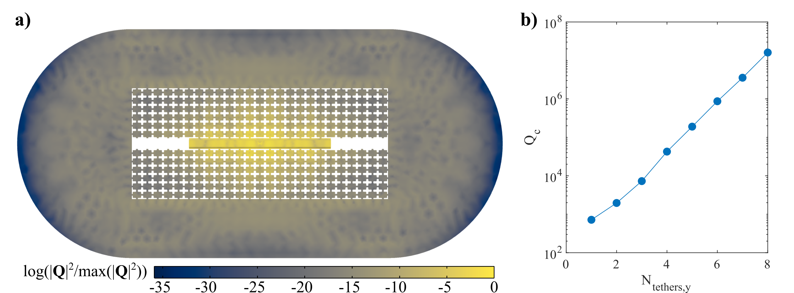
The coupling parameters and were then calculated using the combination of these two simulations (see Eqs. (8) and (9)). The parameter set with the best mode isolation (see Fig. 6 featured nm and nm. This device was then tethered using the phononic tethers shown in Fig. 2 and the number of tethers were varied to calculate mechanical quality factor as a function of number of tether periods, shown in Fig. 7(b).
Appendix C Analysis of Spin Register System
In Figure 8, we present a roadmap to scaling this architecture to form a memory register for superconducting circuits. Since the shunt capacitance far exceeds the capacitance of a single IDT, additional electromechanical resonators in parallel to a single transmon qubit do not significantly change the coupling rates to each resonator. Individual control over each resonator can be obtained with (i.e. cryo-MEMS) electrical switching of contacts to each resonator [75]. If this is not possible, controls can still be obtained in the frequency domain if each resonator frequency is sufficiently detuned from all others and within the tunability range of the transmon. This gives two constraints on the number of parallel resonators we can add: the maximum number of resonators before for each resonator drops below a desired value, and the maximum number of resonators before the frequency spectrum becomes overcrowded.
From electrostatic simulations in COMSOL, , allowing us to add around 10 resonators in parallel without decreasing the coupling to each resonator by more than 15%. Additionally, each resonator can house several quantum emitters, which themselves will be operating at different frequencies due to differing magnetic field and strain environments creating a unique Zeeman effect for each color center. Assuming one implants emitters in each resonator, this creates an easily accessible register of ancillas for a single transmon.
We would like to evaluate overcrowding of the frequency spectrum in this picture. In an ideal case, when we tune the superconducting circuit on resonance with a mechanical mode , we would like the circuit to be approximately coupled only to that acoustic mode. This is the same condition as we presented in Appendix A to assume that we can simplify the dynamics of the SC-phonon-spin system to that of coupling via a single acoustic mode. Thus, when the condition for every mode , then we can suppose that we individually couple to one piezoelectric resonator out of a number of resonators (see Fig. 8). Similarly, we would like to determine the condition where we can assume each piezoelectric resonator can individually couple to a single spin. This complicates the second stage of the system in Appendix A. Assuming that the conditions in Appendix A already holds for each of resonators coupled to the SC qubit, the full Hamiltonian describing the resonator, spin system is
| (45) |
Following exactly from Eqs. 43 and 44 in Appendix A, the required condition for assuming electromechanical coupling to just the th of resonators is that
| (46) |
Similarly, after swapping population into one of the resonator modes, the condition for assuming spin-mechanical coupling to just the th of electron spins is that
| (47) |

We can see from the spin-phonon coupling points in Fig. 6 that frequency crowding can begin to promote Rabi oscillations with populations on the order of of the desired mode when within a 100 MHz frequency window. So parallelization of spins in one resonator would require changing the local magnetic field for each resonator and intelligent spacing of the emitters to promote a wide distribution of resonant frequencies, or sacrificing state tansfer fidelity to a single spin by overcrowding the simulated frequency window of operation. This is not as much of a problem given the order-of-magnitude superior mode suppression on the electromechanical side of the system. Thus, we can comfortably parallelize around piezoelectric resonators to a single SC qubit and 1-3 emitters per resonator. When accounting for the surrounding nuclear spins, we envision that this scaling method can provide a SC qubit with a 10+ nuclear spin memory register.