Single Mode Multi-frequency Factorization Method for the Inverse Source Problem in Acoustic Waveguides
Abstract.
This paper investigates the inverse source problem with a single propagating mode at multiple frequencies in an acoustic waveguide. The goal is to provide both theoretical justifications and efficient algorithms for imaging extended sources using the sampling methods. In contrast to the existing far/near field operator based on the integral over the space variable in the sampling methods, a multi-frequency far-field operator is introduced based on the integral over the frequency variable. This far-field operator is defined in a way to incorporate the possibly non-linear dispersion relation, a unique feature in waveguides. The factorization method is deployed to establish a rigorous characterization of the range support which is the support of source in the direction of wave propagation. A related factorization-based sampling method is also discussed. These sampling methods are shown to be capable of imaging the range support of the source. Numerical examples are provided to illustrate the performance of the sampling methods, including an example to image a complete sound-soft block.
Key Words. inverse source problem, waveguide, multi-frequency, sampling method, Helmholtz equation.
1. Introduction
Inverse scattering is of great importance in non-destructive testing, medical imaging, geophysical exploration and numerous problems associated with target identification. In the last thirty years, sampling methods such as the linear sampling method [18], the factorization method [23] and their extensions have attracted a lot of interests. These sampling methods do not require a priori information about the scattering objects, and provide both theoretical justifications and robust numerical algorithms. There have been recent interests in inverse scattering for waveguides, mainly motivated by their applications in ocean acoustics, non-destructive testing of slender structures, imaging in and of tunnels [3, 22, 31]. One of the early works is the generalized dual space indicator method for underwater imaging [35]. The linear sampling method and factorization method were studied in acoustic waveguides [2, 10, 11, 27] and in elastic waveguides [9, 12]. Theories and applications of sampling methods have been extended to periodic waveguides [8, 33], a time domain linear sampling method [28], sampling methods in electromagnetic waveguide [26, 29]. It is also worth mentioning related imaging methods such as the time migration imaging method in an acoustic terminating waveguide [34], in an electromagnetic waveguide [16] and the time reversal imaging in an electromagnetic terminating waveguide [7]. Relations between the time migration imaging and the factorization method as well as a factorization-based imaging method is discussed in [6]. We also refer to [4] for related discussions on the connections among different imaging methods in the homogeneous space case. It is worth mentioning that a scatterer may be invisible in a waveguide that supports one propagating mode at a single frequency [20].
One difference between the waveguide and the homogeneous whole space is that the waveguide supports finitely many propagating modes and infinitely many evanescent modes at a fixed frequency. The theories of the linear sampling method and factorization method in waveguides [2, 5, 6, 10, 11, 27] have been established using both propagating modes and evanescent modes. Particularly in the far-field, the measurements stem from the propagating modes so that the linear sampling method and factorization method are usually implemented using only the propagating modes. The imaging results are good as far as there are sufficiently many propagating modes. However, an interesting observation made in [27] is that the linear sampling method may not be capable of imaging a complete block ( where a complete block could be an obstacle spanning the entire cross-section) using far-field measurements at a single frequency. This seems not a problem due to the sufficiency or deficiency of propagating modes. This motivates us to investigate further the role of propagating modes. One fact about the propagating modes is that each propagating mode propagates with different group velocity, indicated by the dispersion relation which is a unique feature in waveguide. Intuitively, a single propagating mode at multi-frequencies may help understand further the problem [27] of imaging a complete block with far-field measurements, since the phase (travel time) provides information on the bulk location. The efficiency of using a single propagating mode may be of practical interests in long-distance communication optical devices or tunnels. The above discussions lead to the following question in waveguide imaging: how to make use of a single propagating mode at multiple frequencies in a mathematically rigorous way?
While most of the existing works focus on the sampling methods at a single frequency with full-aperture measurements, the time migration imaging method [34] and the linear sampling method [5] investigated the limited-aperture problem with multiple frequencies. The time domain linear sampling method [28] amounts to use multiple frequency measurements. However, there seems no work to treat the problem with less measurements (such as backscattering measurements obtained from a single propagating mode) at multiple frequencies to lay the theoretical foundation for extended scatterers. This is one of the motivations of this paper: to provide theoretical foundation for extended sources using the sampling methods with a single propagating mode at multiple frequencies. This necessitates the study of the factorization method which provides theoretical justifications for extended sources. Another motivation is to help understand further the problem of imaging a complete block of the waveguide as pointed out in [27]. Though the single frequency linear sampling method may not be capable of imaging a complete block using far-field measurements, measurements with a single mode at multiple frequencies may help locate such a block efficiently. In a certain frequency range, the waveguide supports a single propagating mode so that the far-field measurements stem from such single propagating mode; such a singe mode waveguide was also studied [17] for applications such as invisibility and perfect reflectivity. Based on these two motivations, this paper considers the factorization method for the inverse source problem with single mode multi-frequency measurements for a waveguide that supports a single propagating mode; the measurements are made at one opening of the waveguide, and we call these “backscattering” measurements (where “” is to distinguish the inverse source problem from the inverse scattering problem). A related factorization-based sampling method would also be discussed. These sampling methods are shown to be capable of imaging the range support of the source, but not the support in the cross-section direction. With a single propagating mode, it seems to us that only the support in one direction could be imaged. It was similarly reported in [21] that the support in one direction can be imaged with far-field measurements at a single direction (and its opposite direction).
The methods in this paper inherit the tradition of the classical sampling methods to define a data operator in the far-field. However, in contrast to the existing far/near field operator based on the integral over the space variable, a multi-frequency far-field operator is introduced based on the integral over the frequency variable. This operator has a symmetric factorization which allows us to investigate the factorization method and the factorization-based sampling method. Sampling methods to treat the inverse source problems in the whole space were studied in [1, 21, 25], including the factorization method and direct/orthogonal sampling method. One difference between the waveguide imaging in this paper and the imaging in the whole space arises from the dispersion relation, a unique feature in waveguide. This brings an additional difficulty in defining or factorizing the multi-frequency far-field operator. This paper overcomes this difficulty by incorporating the dispersion relation into the definition of the far-field operator. Another difference is that the measurements under consideration are “backscattering” measurements (in contrast to measurements obtained in two opposite directions in the homogeneous space case [21]); we shall show how to use these less measurements to design appropriate multi-frequency operators to deploy the factorization method. As demonstrated in [1, 21, 25] and the references therein, one may hope to image an approximate support of the source with only one measurement point/direction for imaging in the whole space. This paper reveals a similar result in the waveguide imaging problem: it turns out that the range support of the source can be reconstructed with a single propagating mode at multiple frequencies.
This paper is further organized as follows. Section 2 provides the mathematical model for the inverse source problem in a waveguide. We also briefly discuss the concept of propagating/evanescent modes and dispersion relation, as well as the Green function and the forward problem. The multi-frequency far-field operator is proposed in Section 3, and it is shown that it has a symmetric factorization where the factorized middle operator is coercive. Section 4.1 is devoted to the factorization method which provides a mathematically rigorous characterization of the source support. Motivated by the factorization of the multi-frequency far-field operator, a factorization-based sampling method is then discussed in Section 4.2. Finally numerical examples are provided in Section 5 to illustrate the performance of the two sampling methods to image extended sources. As an extension and application, a numerical example is also provided to illustrate the potential of the multi-frequency sampling methods to image a complete sound-soft block. Section 6 discusses another two multi-frequency operators for sampling methods which impose less restrictive condition on the source. Finally we conclude this paper with a conclusion in Section 7.
2. Mathematical model and problem setup
Let us now introduce the mathematical model of the inverse source problem. The waveguide in is given by , where is the cross-section of the waveguide. In this paper we restrict ourself to the two dimensional case where with denoting the length of , and remark that the extension to the three dimensional case can follow similarly. We consider the model that the boundary of the waveguide is either sound-hard, sound-soft, or mixed (Dirichlet on part of the boundary and Neumann on the remaining boundary). Let us denote the support of the source by with the assumption that and is a domain with Lipschitz boundary. See Figure 1 for an illustration of the problem. For any , let be the coordinate of where is the variable in the range and is the variable in the cross-section.
Let the interrogating wave number be a positive number . Let be the wave field due to the source . The wave field belongs to and satisfies
| (1) | |||||
| (2) | |||||
| (3) |
where the radiation condition is specified in Section 2.1, and denotes either the Dirichlet, Neumann, or a mixed boundary condition, i.e.
| (4) |
with (resp. ) denoting either the top (resp. bottom) or the bottom (resp. top) boundary, is the unit outward normal, and is the set
with denoting the standard Sobolev space consisting of bounded functions whose derivatives belong to .
The goal is to reconstruct the support of the source with a single propagating mode at multiple frequencies. In the case that the waveguide supports one propagating mode, the use of one propagating mode at multiple frequencies amounts to the use of multi-frequency measurements at one measurement point. In particular, the inverse problem is to characterize the support of the source from the following non-vanishing measurements
-
•
“Backscattering” measurements:
(5) where represents the propagating part (far-field) of , is a measurement point at a measurement cross section , and is the range of wavenumber (i.e. frequency).
Here is the range of wavenumber such that the waveguide supports only one propagating mode (which will be specified later in details in Section 2.1). In practice, is such that the measurements are at the far-field of the waveguide (where the contribution from the evanescent part is negligible), this is feasible as the frequencies are always discrete numbers and the evanescent part will be negligible for some . In this paper we fix the notation that waves measured at are called “backscattering” measurements (to distinguish the inverse source problem from the inverse scattering problem) and waves measured at are called “forward scattering” measurements. It is also possible to consider both the “backward and forward scattering” measurements, i.e. measurements at , however this type of measurements may not be applicable in applications where measurements can only be made at one opening of the waveguide. Nevertheless, a detailed remark is to be made in Section 6 concerning this type of measurements.
2.1. Propagating modes
Let us introduce the eigensystem (where we sort ) by
| (6) | |||||
| (7) |
where (defined according to in (4)) denotes either the Dirichlet, Neumann, or mixed boundary condition, i.e.
where denotes the unit outward normal to . Here is either the top or the bottom part of according to (4), and is the remaining part of .
For every fixed with , the following physical wave functions (can be found via separation of variables) are solutions to the Helmholtz equation (1) away from the support of the source
| (8) |
here we have chosen the branch cut of the square root with positive imaginary part, and we call it a propagating mode if and an evanescent mode if .
For our problem, we consider the frequency range such that the waveguide supports only one propagating mode and we set . For later purposes we note that the eigenfunction can be chosen as real-valued with the following explicit expression
We now give the definition of the radiation condition.
Definition 1.
We say a solution to the Helmholtz equation (1) satisfies the radiation condition if
| (9) |
where is the number of the propagating modes, and are coefficients determined by .
2.2. Dispersion relation
For each propagating mode , we identify the concept of group wave number by
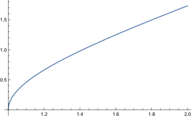
and we call the set the -th “dispersion relation”, which describes how this propagating mode propagates with respect to a given wave number . To illustrate the dispersion relation, in Figure 2 we plot for a two-dimensional waveguide with Dirichlet boundary condition. For sake of completeness, we also define (where the chosen branch cut of the square root is with positive imaginary part) for each evanescent modes when .
This dispersion relation is a unique feature of waveguide (which is in contrast to the linear dispersion appeared in the far-field patterns in an homogeneous background) and poses difficulty in the single mode multi-frequency sampling method.
2.3. Green function and forward problem
Now we introduce the Green function for the waveguide that solves
| (10) | |||||
| (11) | |||||
| (12) |
here the derivatives are with respect to variable . The Green function has the following series expansion [5, 10]
| (13) |
3. The multi-frequency far-field operator and its factorization
The imaging methods under consideration are the qualitative methods or the sampling methods [13, 14, 15, 19], and the goal is to lay the theoretical foundation for extended sources and design efficient imaging algorithms with these measurements. To achieve this, we introduce the following multi-frequency far-field operator and study its properties in this section.
To begin with, set ( and details will be given in later context to motivate its definition). We introduce the single mode multi-frequency far-field operator by
| (15) |
, where represents the propagating part of the wave field , is the Heaviside function
and is such that . The assumption made on is that or with some . We remark that this assumption in the “backscattering” case can be relaxed if both “backward and forward scattering” measurements are available (see Section 6.1), or we can design another less obvious multi-frequency operator (see Section 6.2). We consider this case to fully illustrate the multi-frequency sampling methods in waveguide. Another note is that since otherwise the measurement set (5) would be a vanishing one.
As can be seen, the possibly non-linear dispersion relation is incorporated into the definition of the far-field operator via . In particular, one finds via a direct calculation that which would allow us to investigate the factorization method further. This is in contrast to the inverse source problem in the homogeneous whole space where the dispersion is already linear.
To deploy the factorization method based on the multi-frequency operator (15), we first introduce the operator by
| (16) |
and the operator by
| (17) |
We can directly derive the adjoint operator of , namely by
| (18) |
We have chosen to keep the conjugate in (18) to formally retain the structure of the adjoint. Note that a.e. on the cross section, there is no confusion in the use of square root in (16) and (18). In the following, we give a factorization of the far-field operator. Note that is used in the proof of the following theorem as well.
Theorem 1.
Proof.
Set the propagating part of the Green function . From the expression (14) of and (13), it follows that, for , the propagating part reads
by noting that , we then continue to derive that
and consequently (note that and are real-valued)
Now from the definition of , it follows that
where in the last step, we used the property that a.e. on the cross section so that . The proof is then completed by recalling the definition of , , and in (16), (17), and (18) respectively. ∎
In the following, we study the properties of the factorized operators which are needed to investigate the factorization method in the next section.
Theorem 2.
Proof.
Recall that with or with some , then is self adjoint; moreover from the definition of in (17)
then we can directly prove the theorem by noting that or (and note that as the measurements are non-vanishing). This completes the proof. ∎
Lemma 2.
The operator given by (18) is compact and has dense range in .
Proof.
From the definition (18) of , for any we have that
and since , one can directly derive that by taking the derivative of with respect to . Then we can conclude the compactness of from the compact embedding from into .
To show the dense range of in , it is sufficient to show that is injective. We prove this by contradiction. Indeed if there exists such that , i.e.,
note that , then we can derive that
where is the Fourier transform , and is the characteristic function such that if and if . This implies that vanishes and thereby vanishes in . This proves that is injective and hence has dense range in . This completes the proof. ∎
4. The sampling methods
In this section, we study the sampling methods [13, 14, 15, 19, 24] where the goal is to lay the theoretical foundation for extended sources and design efficient imaging algorithms with the single mode multi-frequency measurements. The factorization method [23] has established a mathematically rigorous characterization of extended scatterers in the classical setting and has been applied to the inverse source problem in the homogeneous whole space [21] with sparse multi-frequency measurements. There have been relevant work on the factorization method in waveguide with a single frequency, yet we aim to deploy the factorization method with a single propagating mode at multiple frequencies. Based on the multi-frequency operator and its properties derived in Section 3, the factorization method is to be established in Section 4.1. Moreover, the factorization of the multi-frequency operator may also lead to a factorization-based sampling method, as demonstrated in waveguide imaging in the single frequency case [6] and the inverse source problem in the homogeneous space [25] with sparse multi-frequency measurements. In Section 4.2 the factorization-based sampling method is to be analyzed.
4.1. The factorization method
In this section, we shall investigate the factorization method which gives a mathematically rigorous characterization of the range support of the source. To begin with, denote by
| (20) |
where is a circle centered at with radius , and denotes its area.
We first give a characterization of the range of . Let , and recall that . For any domain , denote by the characteristic function such that if and if . For any point , we call the range coordinate and the cross-section coordinate.
Lemma 3.
Proof.
(1). If , then there must exist and such that . Let , then and it is directly verified that
This proves that . Now a direct calculation
yields that is indeed independent of the cross-section coordinate , i.e. for any and , . This proves the first part.
(2). If , for any sufficiently small with , assume on the contrary that for a . Then there exists a such that
for any . Noting the common term , the above equation is reduced to
| (21) |
where in .
By recalling the multi-dimensional Fourier transform
| (22) |
and the Radon transform for a unit direction that
| (23) |
where represents the hyperplane orthogonal to . From the Fourier slice theorem [30, Theorem 1.1]
| (24) |
where denotes the one-dimensional Fourier transform.
Now we can derive from (21) that
and thereby
| (25) |
Then we can derive that
However and yields a contradiction (since ). This prove the second part. These prove the Lemma. ∎
As can be seen from Lemma 3 part , the depends on the sampling range coordinate . The following corollary removes this dependence with an extra geometric assumption on .
Corollary 1.
Assume in addition that the minimal width of is bounded below by a positive constant, i.e., where . For any sampling point in with range coordinate , it holds that
-
(1)
If , let be any given small tolerance level, then there exists a positive such that for any with and any positive , .
-
(2)
If , then for any sufficiently small with and any with range coordinate , .
Proof.
The only difference is in part (1). We highlight the difference. Assume that . Since the minimal width of is bounded below by a positive constant, i.e., , then for any range coordinate with , there must exist such that for all . Now let , then and it is directly verified that
This proves that . Using the same argument before, we prove the corollary. ∎
Applying Theorem 2 and Lemma 2, the following Lemma is a direct application of [24, Corollary 1.22].
Now we can prove the following theorem. Let be the eigensystem of the self-adjoint operator and let denote the inner product in .
Theorem 3.
For any sampling point in with range coordinate , it holds that
-
(1)
If , then there exists a positive depending on such that for any with range coordinate , and moreover
(26) -
(2)
If , then for any sufficiently small with and any with range coordinate , and moreover
(27)
Proof.
Corollary 2.
Assume in addition that the minimal width of is bounded below by a positive constant, i.e., where . Then we have that
Remark 1.
Corollary 2 implies that the can be chosen as a fixed constant for all the sampling points when implementing the factorization method. In particular, we can choose as a small number such that is less than a tolerance level that one is seeking for. If there is no such assumption as in Corollary 2, we can still chose as a fixed tolerance level, and in this case, the part whose width is very small may not be reconstructed as indicated by Theorem 3 and Lemma 3 (and its proof). However since is the tolerance level, the factorization method theoretically would still yield a sufficiently good image.
4.2. The factorization-based sampling method
In this section, we investigate a factorization-based multi-frequency sampling method with imaging function given by
| (28) |
Its property is given by the following theorem.
Theorem 4.
There exists positive constants and such that
| (29) |
Proof.
From the factorization of the far-field operator, it first follows that
The lower bound then follows from the coercivity of in Theorem 2, the upper bound follows directly from the boundedness of . This completes the proof of the theorem. ∎
Theorem 4 implies that is qualitatively the same as without the knowledge of . The following Lemma gives the explicit expression of .
Lemma 5.
It holds that
| (30) |
where the above quotient is understood in the limit sense when .
Proof.
From the definition of , we directly have that
where the above quotient is understood in the limit sense when . This completes the proof. ∎
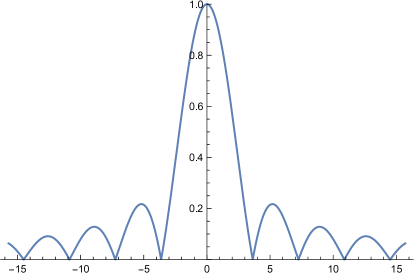
From the explicit formula of in Lemma 5, we find that its maximum is obtained at and that is oscillatory and decaying to zero when becomes large. We illustrate this property in Figure 3 with a fixed and , where we plot for a two-dimensional waveguide with Dirichlet boundary condition where and . We further remark that the function is only sensitive to the range sampling coordinate which can be directly observed from (30). As a summary, it is heuristically observed that peak in as the sampling point samples in a sampling region since there always exists such that for any . Together with Theorem 4 it is inferred that is qualitatively the same as without the knowledge of . Though the factorization-based sampling method is not as mathematically rigorous as the factorization method, it is heuristically inferred that peaks in which is the range support of in the waveguide.
5. Numerical examples
In this section, we present a variety of numerical examples in two dimensions to illustrate the performance of the single mode multi-frequency sampling methods.
We generate the synthetic data using the finite element computational software Netgen/NGSolve [32]. To be more precise, the computational domain is and the measurements are at a random location on the cross section . We apply a brick Perfectly Matched Layer (PML) in the domain and choose PML absorbing coefficient . In all of the numerical examples, we apply the second order finite element to solve for the wave field where the source is constant ; the mesh size is chosen as where we recall that denotes the length of the cross section. We further add Gaussian noise to the synthetic data to implement the imaging function in Matlab.
We first illustrate the implementation of the factorization method and the factorization-based sampling method. Let be the set of equally discretized wave numbers, this yields the discretized multi-frequency far-field matrix of its continuous counterpart in (15).
-
(1)
The factorization method. Let be the eigensystem of the self-adjoint matrix . The imaging function indicated by the factorization method is
where is a fixed tolerance level, and is the discretization of (20) at the multiple wavenumbers (i.e. multi-frequencies) . The represents the inner product of two vectors that arise from the discretization of their continuous counterparts. The main Theorem 2 of the factorization method implies that is bounded below by for and almost vanishes for where is a neighborhood of the support within the tolerance level . We choose tolerance level in all of the numerical examples. Though we have fixed this tolerance level, we have tested other small tolerance levels and haven’t found any visual difference on the imaging results.


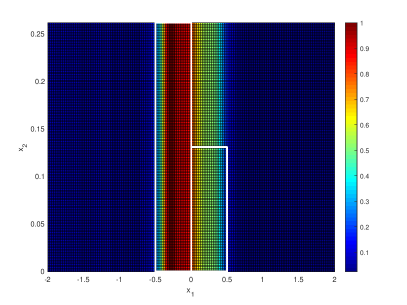
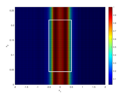
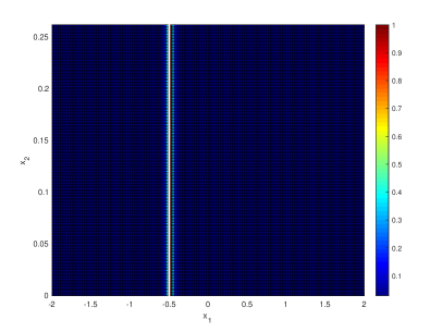
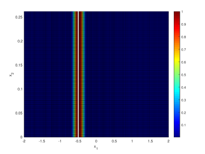
Figure 4. The range reconstruction of a rectangular source in a Neumann boundary condition waveguide. The exact support of the source is indicated by the white solid lines. Top: 47 frequencies. Middle: 23 frequencies. Bottom: 11 frequencies. Left: the factorization method. Right: the factorization-based sampling method. -
(2)
The factorization-based sampling method. Let be the discretization of at the multiple wavenumbers (i.e. multi-frequencies) . The imaging function indicated by the factorization-based sampling method is
The represents the inner product of two vectors that arise from the discretization of their continuous counterparts.
For the visualization, we plot both and over the sampling region and we always normalize them such that their maximum value are respectively.
5.1. Number of frequencies
The first set of numerical examples is to illustrate how the number of frequencies affects the image. We consider a rectangular source in a two dimensional waveguide with Neumann boundary condition and . In this case, the first propagating mode is . The range reconstruction of the rectangular source is shown in Figure 4 where we have considered three different cases:
-
•
Case I: 47 frequencies in the set .
-
•
Case II: 23 frequencies in the set .
-
•
Case III: 11 frequencies in the set .
It is observed that the factorization method performs better with more frequencies, while the factorization-based sampling method performs almost the same in these three different cases. Such a difference may be due to that the factorization method explicitly involves solving an ill-posed equation so that a more sophisticated discretization is perhaps needed in the implementation. Another observation is that the imaging function of the factorization method sharply vanish outside the range support (which agrees with the factorization method main Theorem 3), and the imaging function of the factorization-based sampling method gradually becomes small as the sampling point samples away from the range support (which also agrees with the main theorem of the factorization-based sampling method Theorem 4 and the property of the point spread function ).
5.2. A “complete block” source
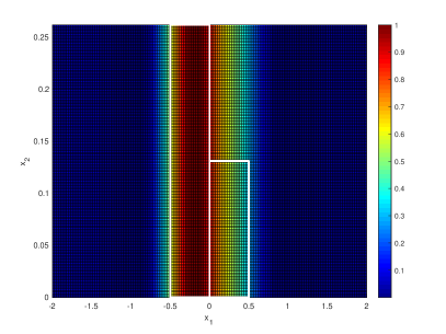
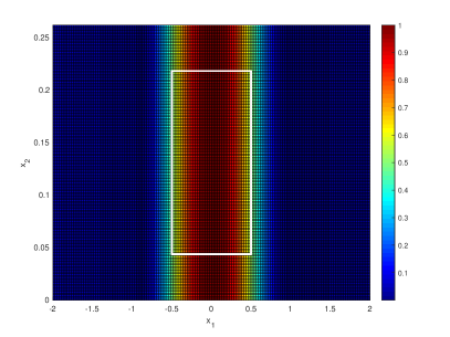
Using sampling methods to image of a complete block of the waveguide is an interesting problem [27]. The L-shape case under consideration in this subsection is similar to a complete block case considered in [27]. Results in Figure 5 imply that a “complete block” source (i.e. a source which spans the entire cross-section) can be reconstructed with our sampling methods with multi-frequency measurements. This is due to that the multi-frequency measurements make use of the phase (travel time) which provides information on the bulk location.
5.3. Different boundary conditions
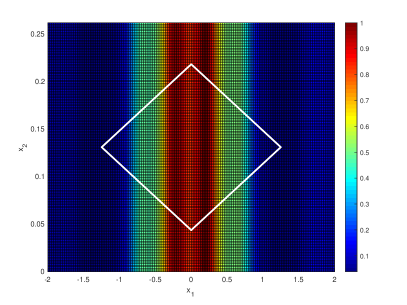
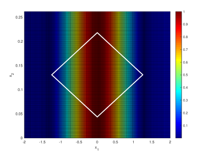
We further illustrate the performance of the sampling methods with different boundary conditions of the waveguide. In this regard, a two dimensional waveguide with a mixed boundary condition and is considered. The mixed boundary condition is a Dirichlet boundary condition on the top boundary and a Neumann boundary condition on the bottom boundary. The first propagating mode in this case is , and the corresponding dispersion relation reads . Note that this mixed boundary condition yields a non-linear dispersion relation. The first passband corresponds to , and the following numerical example is produced with 41 wavenumbers (i.e. frequencies) in the set .
The first row of Figure 6 is the range reconstruction of a rectangular source. The support of the source is the same as the one in Figure 4 in order to compare performance with respect to different boundary conditions, and it is observed that the performances of the sampling methods in these two different boundary condition cases are similar. The difficulty arising from the non-linear dispersion relation in the mixed boundary condition case is overcame via the carefully defined far-field operator.
The second row of Figure 6 is the range reconstruction of a rhombus shape source. Note that the rhombus shape source does not satisfy the assumption in Corollary 2. In particular the left and right corner of the rhombus shape source would be reconstructed with certain tolerance for the factorization method as indicated by Theorem 3 and Lemma 3 (and its proof). Since the left and right corners are sharp, the factorization-based sampling method may also reconstruct the support with certain tolerance. These observations are illustrated by the the second row of Figure 6.
5.4. A complete sound-soft block
In the last subsection, we illustrate how to image a complete block (with sound soft boundary condition) by a preliminary numerical example. It is observed in [27] that, a complete block of a waveguide can be reconstructed with near field measurements, however it may not be reconstructed with far-field measurements using the linear sampling method at a single frequency. With the multi-frequency measurements in our framework, it is possible to image such a complete block using far-field measurements. Though we have demonstrated this via the inverse source problem, to be more convincing we show a preliminary example for imaging a sound soft block. The waveguide is with Neumann boundary condition and . The complete block is at . In this case, the scattered wave field at far-field due to a point source at transmitter location can be written explicitly and we further add noise to this wave field to generate our synthetic data.
The difference between the block case and the source case can be interpreted though the travel time: the travel time in the block case roughly doubles the one in the source case (where the block and the source are at the same location); this is because the wave travel from the transmitter to the block then back to the receiver in the block case while the wave just travel from the source to the receiver in the source case. Therefore the functions and have to be modified by doubling their phases, i.e. and . This is the only change in our implementation to image a complete block with the sampling methods. Figure 7 illustrate the performance of the sampling methods to image a complete sound soft block. frequencies in the set are used. It is observed that the block is correctly located and a sharper result is given by the factorization method. The obstacle/block case is more complicated than the source case and a complete theoretical justification is part of our future work.
6. Remark on designs of multi-frequency operator and assumptions on the source
In the above discussions of the multi-frequency sampling methods, we have made the assumption on the source that or with some . Indeed it is possible to relax this assumption by designing other multi-frequency operators. We introduce in this section another two multi-frequency operators to remark that the sampling methods can require less restrictive conditions on the source; this may be of interest to readers who is more interested in minimal assumption on the source. The first operator in Section 6.1 is to consider both “backward and forward scattering” measurements; the second operator in Section 6.2 still uses only the “backscattering” measurements (which is less obvious to design) and it usually uses information in part of the frequency range. Their advantages are that the sampling methods with these operators would require a less restrictive assumption that almost everywhere for with some constant phase ; their drawbacks are that either more measurements have to be used (Section 6.1) or information in part of the frequency range can usually be utilized (Section 6.2). The first technique in Section 6.1 is in the same spirit of the inverse source problem in the whole space [21] (that uses measurements from two opposite directions); the second technique in Section 6.2 seems new which may facilitate further advancement of the multi-frequency factorization method using only the backscattering measurements. In the following we briefly show how to generalize the results in Section 3–4 using these two multi-frequency operators.
6.1. A multi-frequency operator based on “backward and forward scattering” measurements
One way to relax the assumption on the source is to consider both the “backward and forward scattering” measurements, i.e. measurements at and . In this case, we introduce a similar multi-frequency far-field operator by
| (31) |
. One can then verify that
and we can proceed as in Theorem 1 to conclude that with
| (32) |
Though there is no assumption on to derive the factorization in the “backward and forward scattering” measurement case, an assumption that almost everywhere for with some would then be added to ensure the coercivity of an operator related to . To show the coercivity, we introduce for a generic bounded operator that
Now we have
Lemma 6.
Suppose that for some constant phase , then we have that is self-adjoint and coercive.
Proof.
From the assumption that for some constant phase , we have that
| (33) |
and that
| (34) |
for some positive constant . This completes the proof. ∎
Lemma 6 would then allow us to derive a version of the factorization method (that requires less restrictive conditions on the source ) which is in the same spirit of the inverse source problem in the whole space [21] (that uses measurements from two opposite directions). However we are mainly concerned with the most interesting “backscattering” case and we shall discuss another possible multi-frequency operator in the next section. We then finalize by generalizing the main results of the factorization method and the factorization-based sampling method using and .
6.2. Another multi-frequency operator based on “backscattering” measurements
Indeed we can still impose less restrictive conditions on the source in the case of “backscattering” by designing another multi-frequency operator as follows. Here we introduce a multi-frequency far-field operator by
| (35) |
where with being a positive constant that is determined later (by the coercivity assumption of a certain operator), and . Note that for , .
In this case, similar to the role of in Section 3, one finds via a direct calculation that (for ) which linearizes the dispersion in another (though less obvious) way. In principle, one may find other ways to design multi-frequency operators. The possible drawback is seen as that has range in which is a subset of if , this implies that information in part of the frequency range is only used if . Nevertheless, with such a design of the multi-frequency operator, we are able to derive a factorization method with only the “backscattering” measurements with less restrictive conditions on the source . We also refer to [21] for a discussion on an extension of the factorization method to “backscattering” measurements.
The operators and remain formally the same as in (16) and (18), respectively (by only replacing by ). The difference is the operator defined via
| (36) |
Using the definition of (35), we can prove similarly that
Next we investigate the coercivity of the operator . Recall that is given by (32) in Section 6.1.
Theorem 5.
Suppose that is positive and coercive for some constant phase . Let be given by (36), then there exists a positive constant such that the operator is self-adjoint, coercive and
for some positive constant .
Proof.
We first introduce in the proof to avoid writing long equations so that the presentation is clean and compact. From the definitions of in (36), we have that
whereby
| (37) |
Now from the expressions of in (37) and of in (33),
| (38) | |||||
Having in a fixed sampling region, then is bounded above so that we can always choose such that for a sufficiently small , thereby
for some sufficiently small . Note that , therefore we can derive from (38) that
| (39) |
for some sufficiently small . Together with the assumption that is coercive with estimate (34), we have that
for some positive constant . This completes the proof. ∎
6.3. Generalization of the main results
Based on the discussion of the multi-frequency operators and , we discuss below how to generalize the main Theorems 3 and 4. In particular, we can prove exactly in the same way that Theorem 3 holds when replacing by the self-adjoint operator or , where and . On the other hand, Theorem 4 for the factorization-based sampling method holds when replacing by or .
Acknowledgement
The author greatly thanks the anonymous referees for their helpful comments that have improved the quality of this manuscript.
7. Conclusion
The factorization method is investigated to treat the inverse source problem in waveguides with a single propagating mode at multiple frequencies. A factorization-based sampling method is also discussed. The main result of the factorization method is to provide both theoretical justifications and efficient imaging algorithms to image extended sources. One key step is to use the multi-frequency measurements to introduce the multi-frequency far-field operator, which is carefully designed to incorporate the possibly non-linear dispersion relation. We also emphasize that the measurements under consideration are “backscattering” measurements (in contrast to measurements obtained in two opposite directions), and we have shown how to use these less measurements to design appropriate multi-frequency operators to deploy the factorization method. Each multi-frequency operator can be factorized as which plays a fundamental role in the mathematically rigorous justification of the factorization method. A factorization-based sampling method is also discussed, where the factorization and a relevant point spread function play important roles. The sampling methods are capable to image the range support of the extended sources.
Another interesting observation is the potential to image a complete block, since the linear sampling method may not be capable of imaging such a complete block using far-field measurements at a single frequency. We provide examples to image both a complete source block and a complete obstacle block using the multi-frequency sampling methods. It is shown that the use of one propagating mode at multiple frequencies can efficiently locate a complete block where such efficiency may be of practical interests in long-distance communication optical devices or tunnels.
This work establishes the fundamental result with a single propagating mode at multiple frequencies. One direction of future work will be to investigate the factorization method in waveguide imaging using multiple propagating modes to establish theoretical justifications for extended scatterers in inverse obstacle/medium problems.
References
- [1] A Alzaalig, G Hu, X Liu, and J Sun. Fast acoustic source imaging using multi-frequency sparse data, Inverse Problems 36, 025009, 2020.
- [2] T Arens, D Gintides, and A Lechleiter. Direct and inverse medium scattering in a three-dimensional homogeneous planar waveguide. SIAM J. Appl. Math. 71(3), 753–772, 2011.
- [3] AB Baggeroer, WA Kuperman, and PN Mikhalevsky. An overview of matched field methods in ocean acoustics. IEEE Journal of Oceanic Engineering 18(4), 401–424, 1993.
- [4] C Bellis, M Bonnet, and F Cakoni. Acoustic inverse scattering using topological derivative of far-field measurements-based l2 cost functionals. Inverse Problems 29, 075012, 2013.
- [5] L Borcea, F Cakoni, and S Meng. A direct approach to imaging in a waveguide with perturbed geometry, J. Comput. Phys. 392, 556–577, 2019.
- [6] L Borcea and S Meng. Factorization method versus migration imaging in a waveguide. Inverse Problems 35(12),124006, 2019.
- [7] L Borcea and DL Nguyen. Imaging with electromagnetic waves in terminating waveguides. Inverse Probl. Imaging 10, 915–941, 2016.
- [8] L Bourgeois and S Fliss. On the identification of defects in a periodic waveguide from far field data. Inverse Problems 30(9), 095004, 2014.
- [9] L Bourgeois, F Le Louër, and E Lunéville. On the use of Lamb modes in the linear sampling method for elastic waveguides. Inverse Problems 27(5), 055001, 2011.
- [10] L Bourgeois and E Lunéville. The linear sampling method in a waveguide: a modal formulation. Inverse problems 24(1), 015018, 2008.
- [11] L Bourgeois and E Lunéville. On the use of sampling methods to identify cracks in acoustic waveguides. Inverse Problems 28(10), 105011, 2012.
- [12] L Bourgeois and E Lunéville. On the use of the linear sampling method to identify cracks in elastic waveguides. Inverse Problems 29(2), 025017, 2013.
- [13] F Cakoni and D Colton. Qualitative Approach to Inverse Scattering Theory, Springer, 2016.
- [14] F Cakoni, D Colton, and H Haddar. Inverse Scattering Theory and Transmission Eigenvalues, SIAM, 2016.
- [15] F Cakoni, D Colton, and P Monk. The Linear Sampling Method in Inverse Electromagnetic Scattering, SIAM, 2011.
- [16] J Chen and G Huang. A direct imaging method for inverse electromagnetic scattering problem in rectangular waveguide. Communications in Computational Physics 23, 1415–1433, 2017.
- [17] L Chesnel, SA Nazarov and V Pagneux. Invisibility and perfect reflectivity in waveguides with finite length branches. SIAM Journal on Applied Mathematics 78(4), 2176–2199, 2018.
- [18] D Colton and A Kirsch. A simple method for solving inverse scattering problems in the resonance region. Inverse Problems 12, 383–393, 1996.
- [19] D Colton and R Kress. Inverse Acoustic and Electromagnetic Scattering Theory, Springer Nature, New York, 2019.
- [20] ASBB Dhia, L Chesnel, and SA Nazarov. Perfect transmission invisibility for waveguides with sound hard walls. Journal de Mathématiques Pures et Appliquées 111(9), 79–105, 2018.
- [21] R Griesmaier and C Schmiedecke. A factorization method for multi-frequency inverse source problems with sparse far-field measurements, SIAM J. Imag. Sci. 10, 2119–2139, 2017.
- [22] A Haack, J Schreyer, and G Jackel. State-of-the-art of non-destructive testing methods for determining the state of a tunnel lining. Tunnelling and Underground Space Technology incorporating Trenchless Technology Research 4(10), 413–431, 1995.
- [23] A Kirsch. Characterization of the shape of a scattering obstacle using the spectral data of the far-field operator, Inverse Problems 14, 1489–1512, 1998.
- [24] A Kirsch and N Grinberg. The Factorization Method for Inverse Problems, Oxford University Press, Oxford, 2008.
- [25] X Liu and S Meng. A multi-frequency sampling method for the inverse source problems with sparse measurements, arXiv:2109.01434.
- [26] S Meng. A sampling type method in an electromagnetic waveguide. Inverse Probl. Imaging 15(4), 745–762, 2021.
- [27] P Monk and V Selgas. Sampling type methods for an inverse waveguide problem. Inverse Probl. Imaging 6(4), 709–747, 2012.
- [28] P Monk and V Selgas. An inverse acoustic waveguide problem in the time domain. Inverse Problems 32(5), 055001, 2016.
- [29] P Monk, V Selgas, and F Yang. Near-field linear sampling method for an inverse problem in an electromagnetic waveguide. Inverse Problems 35(6), 065001, 2019.
- [30] F Natterer. The Mathematics of Computerized Tomography, SIAM, 2001.
- [31] P Rizzo, A Marzani, J Bruck, et al. Ultrasonic guided waves for nondestructive evaluation/structural health monitoring of trusses. Measurement science and technology 21(4), 045701, 2010.
- [32] J Schöberl. Netgen an advancing front 2d/3d-mesh generator based on abstract rules. Computing and visualization in science 1(1), 41–52, 1997.
- [33] J Sun and C Zheng. Reconstruction of obstacles embedded in waveguides. Contemporary Mathematics 586, 341–350, 2013.
- [34] C Tsogka, DA Mitsoudis, and S Papadimitropoulos. Imaging extended reflectors in a terminating waveguide. SIAM J. Imag. Sci. 11(2), 1680–1716, 2018.
- [35] Y Xu, C Mawata, and W Lin. Generalized dual space indicator method for underwater imaging. Inverse Problems 16(6),1761, 2000.