Osaka Institute of Technology
1-79-1 Kitayama, Hirakata, Osaka 573-0196, Japan
11email: [email protected]
Selfie Taking with Facial Expression Recognition Using Omni-directional Camera
Abstract
Recent studies have shown that visually impaired people have desires to take selfies in the same way as sighted people do to record their photos and share them with others. Although support applications using sound and vibration have been developed to help visually impaired people take selfies using smartphone cameras, it is still difficult to capture everyone in the angle of view, and it is also difficult to confirm that they all have good expressions in the photo. To mitigate these issues, we propose a method to take selfies with multiple people using an omni-directional camera. Specifically, a user takes a few seconds of video with an omni-directional camera, followed by face detection on all frames. The proposed method then eliminates false face detections and complements undetected ones considering the consistency across all frames. After performing facial expression recognition on all the frames, the proposed method finally extracts the frame in which the participants are happiest, and generates a perspective projection image in which all the participants are in the angle of view from the omni-directional frame. In experiments, we use several scenes with different number of people taken to demonstrate the effectiveness of the proposed method.
Keywords:
selfie omni-directional camera face detection facial expression recognition perspective projection image.1 Introduction
According to a survey reported in 2011[11], about 71% of visually impaired people had recently taken photos. This suggests that many visually impaired people have the same desire to take photos and share them with others in the same way as sighted people do. On the other hand, a survey published in 2021 reported that about 90% of visually impaired people use iPhone’s VoiceOver app, which has a function that tells how many people are within the field of view of the camera when taking a photo of people, allowing the visually impaired to take photos of people. However, since this function recognizes a face as long as 70% of the face is in the frame, when a person takes a selfie with multiple people, they may not be in the frame. In addition, it is difficult for them to distinguish whether or not the photographed persons have good facial expressions.
In this study, focusing on a situation in which visually impaired people take selfies, we propose a method that enables to take selfies with multiple people using an omni-directional camera. Specifically, a user first takes a few seconds of video using an omni-directional camera. Next, the proposed method performs face detection on all frames, and then eliminates false face detections and complements undetected ones considering the consistency across all frames. After performing facial expression recognition on all the frames, the proposed method finally extracts the frame in which the participants are happiest, and generates a perspective projection image in which all the participants are in the angle of view from the omni-directional frame.
2 Related Work
This section introduces photography systems that support the visually impaired and methods using omni-directional images related to this study. Several methods have been proposed to assist visually impaired people in taking photographs. Jayant et al. proposed EasySnap[11, 19], which enables users to adjust the composition, zoom level, and brightness of the subject according to voice instructions. They also proposed PortraitFramer[11], which enables users to be informed of the positions of faces by vibration when the smartphone screen is touched, allowing the users to move the camera to achieve the desired composition. Vázquez et al.[18] proposed to automatically adjust the camera roll, and Balata et al.[5] provide feedback to users on compositions of their photos using center and golden ratio compositions. These methods enable users to confirm the composition before taking photos. In addition, services and systems have been proposed to support visually impaired people [6, 1, 2, 4, 3, 15, 14, 13, 8] in their daily lives. Although these help visually impaired people obtain information through photographs, none of them are intended to take selfies.
As mentioned above, although many support systems have been proposed that use the common camera in smartphones, it is still difficult for the visually impaired to grasp the positions of objects to be photographed and adjust the camera so that they are included within the angle of view of the camera. To handle these systems, the users need to be trained to a certain degree. Gonzalez Penuela et al. [9] also reported that it is difficult for visually impaired people to reliably follow voice instructions such as ”turn your smartphone 45° to the right”, and that some users find the vibratory feedback confusing and uncomfortable.
To solve these problems, methods using an omni-directional camera that can capture an image of an object without pointing the camera at the object has been proposed. Based on the results of Jokela et al.’s survey [12] on the usability of omni-directional camera, taking selfies and group photos is important use of an omni-directional camera. However, they reported that omni-directional images containing a lot of information can sometimes be uninteresting. To address this issue, Iwamura et al. [10] proposed VizPhoto, which selects an arbitrary object from the detected objects, and outputs a perspective projection image. Although this method succeeds in capturing the object within the angle of view, it does not aim to take selfies and does not take human facial expressions into consideration. As a study of selfies using an omni-directional camera, obata et al. [16] proposed a system for sending omni-directional video messages to family members who are separated from each other during a meal in order to communicate with them. As one of the functions of this system, the face image of the person of interest in the omni-directional video is combined with the frontal view of the omni-directional video by a face tracking function to share both the face and the view the user are seeing. However, this research focuses on communication through video messages, and does not aim to take selfies with good facial expressions.
Unlike the previous studies, this study focuses on taking selfies and aims to output a perspective projection image in which all the faces are in the angle of view and have good facial expressions.
3 Proposed Method
3.1 Outline
In the proposed method, first, a user takes a few seconds of omni-directional video. Second, the method performs face detection for all persons in all frames in the omni-directional video. Third, the method eliminates false detection and interpolates undetected faces. Fourth, the method performs facial expression recognition on all the frames, and extract the frame with the highest happiness value for all the participants. Finally, the method transforms the omni-directional image to the perspective projection image. In this step, it calculates the image center and the angle of view so that all the faces are within the frame. In the following, we describe each step in details.
3.2 Omni-directional Video Capture
In the proposed method, a user takes a selfie with an omni-directional camera according to the following three conditions.
-
1.
A user extends his/her arm and holds the camera at about the same height as his/her shoulder.
-
2.
Persons to be photographed are within about 1.5 meters from the camera.
-
3.
Persons to be photographed gather in one direction from the camera and do not spread out to the sides.
This study also assumes that the downward direction of the omni-directional image is the direction of gravity in the real world, using the direction of gravity obtained by the acceleration sensor inside the omni-directional camera.
3.3 Frame Extraction with Face Detection and Expression Recognition
3.3.1 Face Detection on All Frames
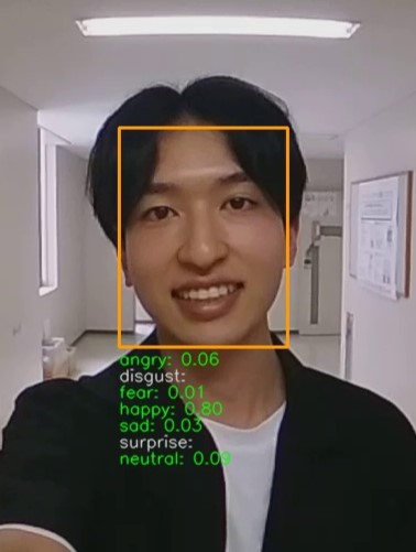
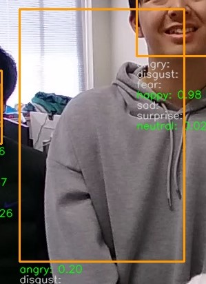
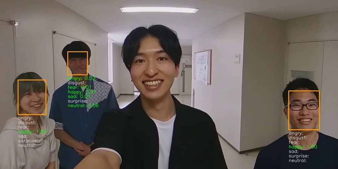
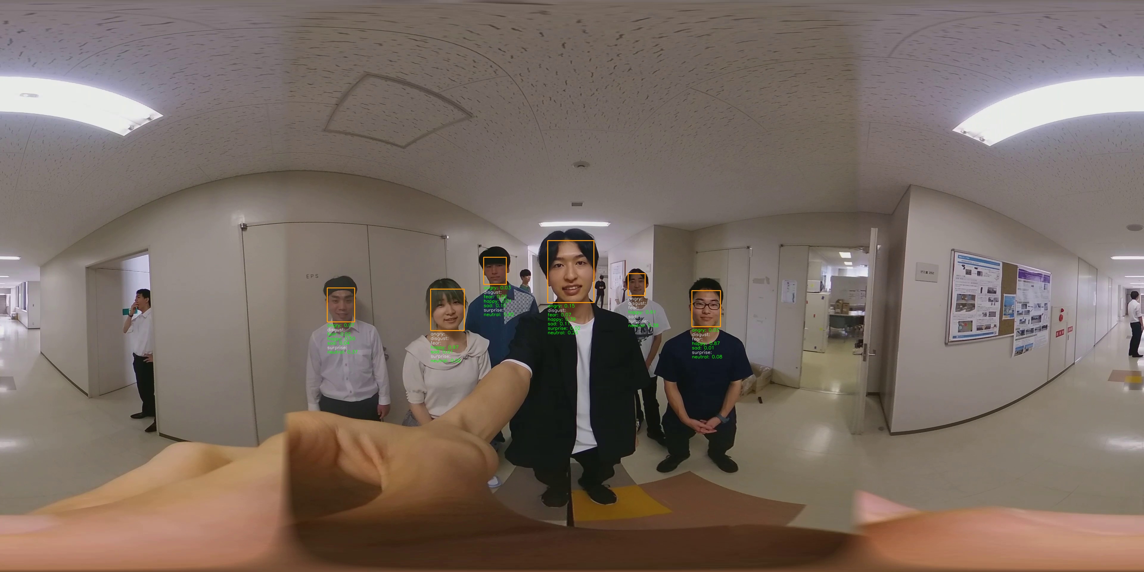
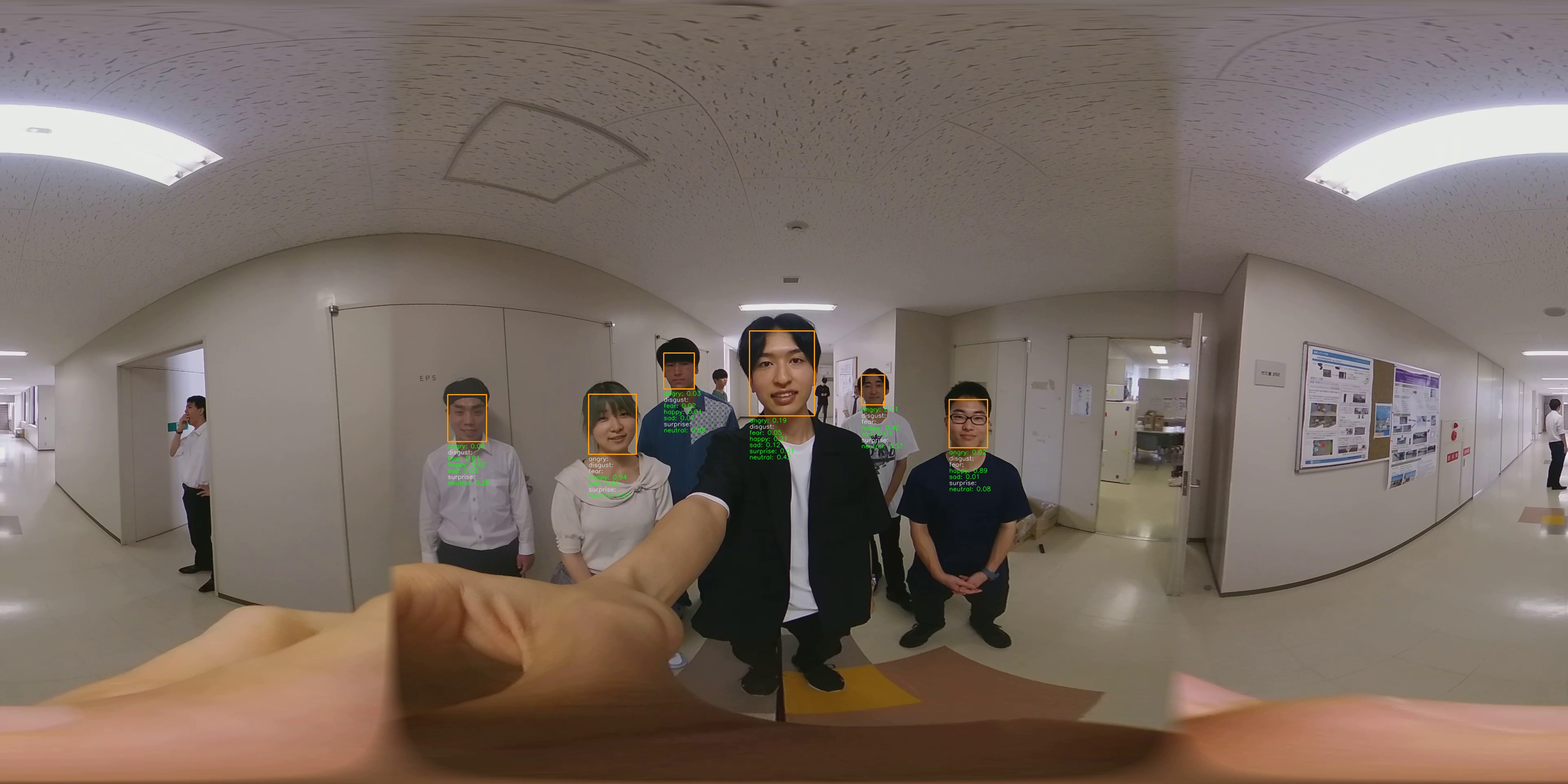
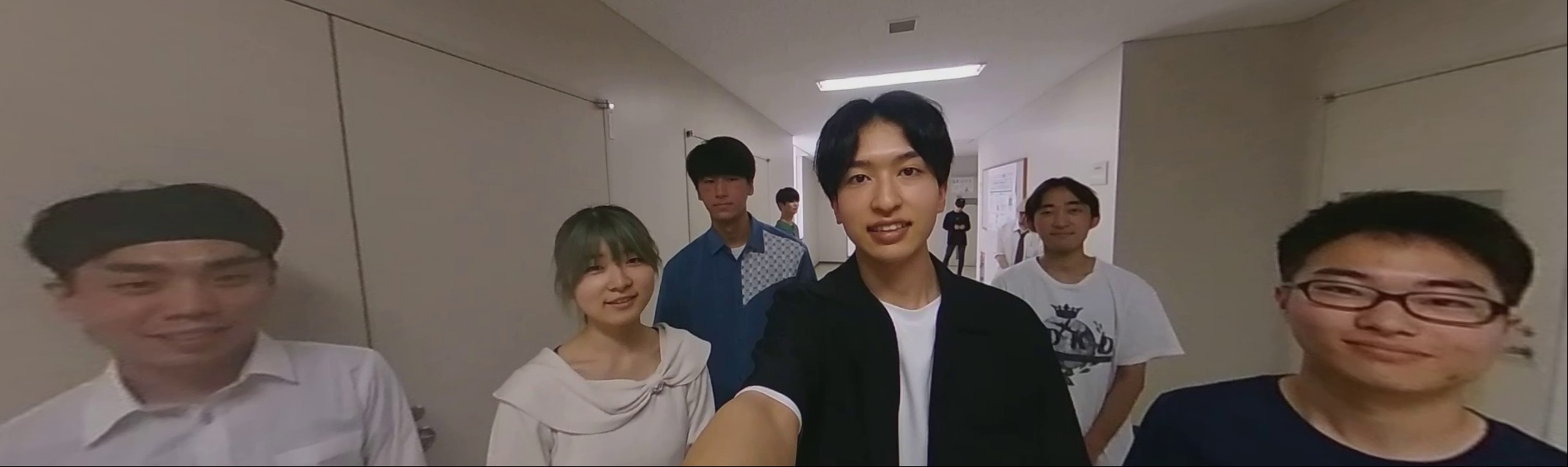
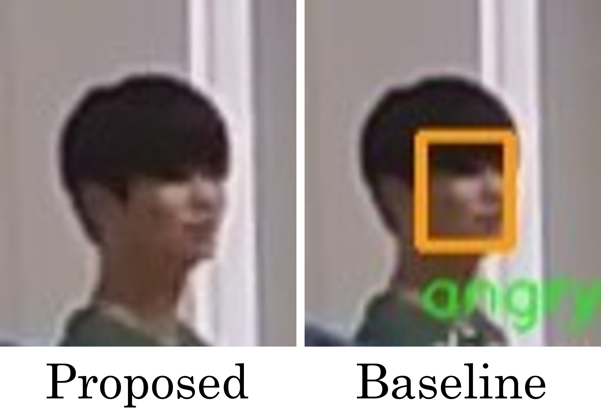
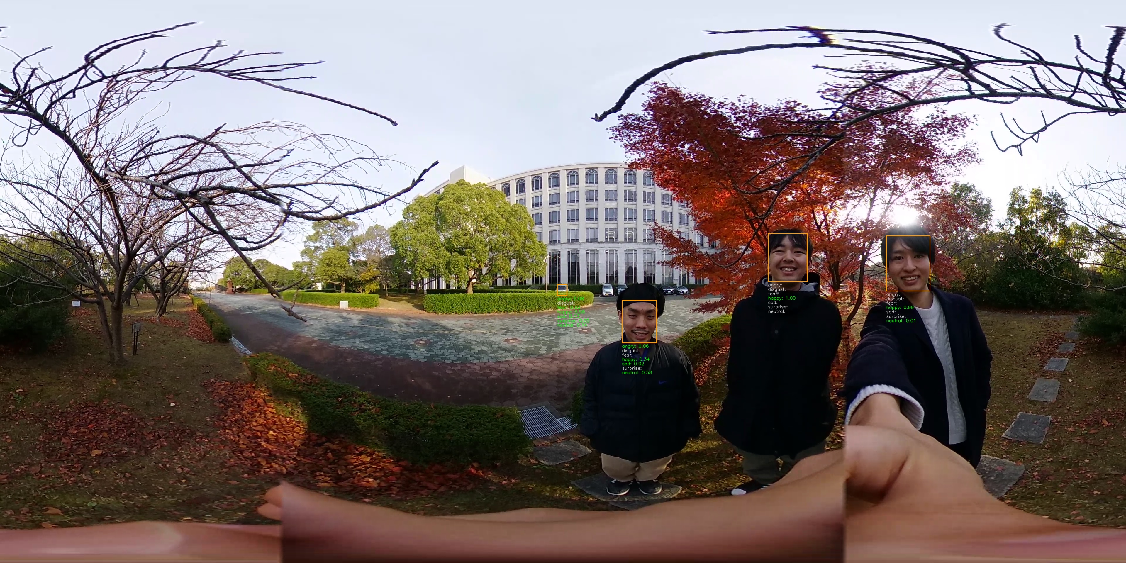
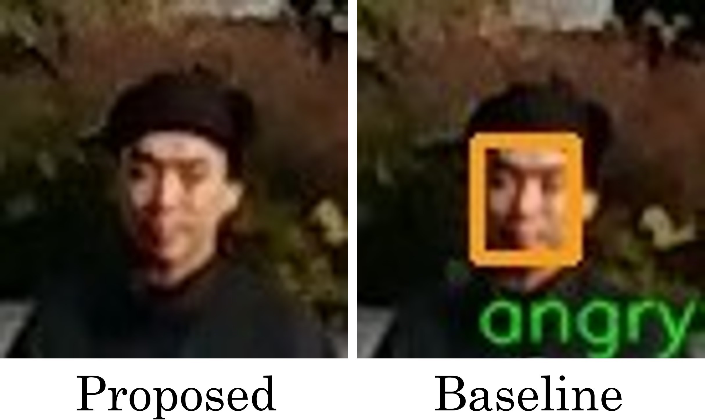
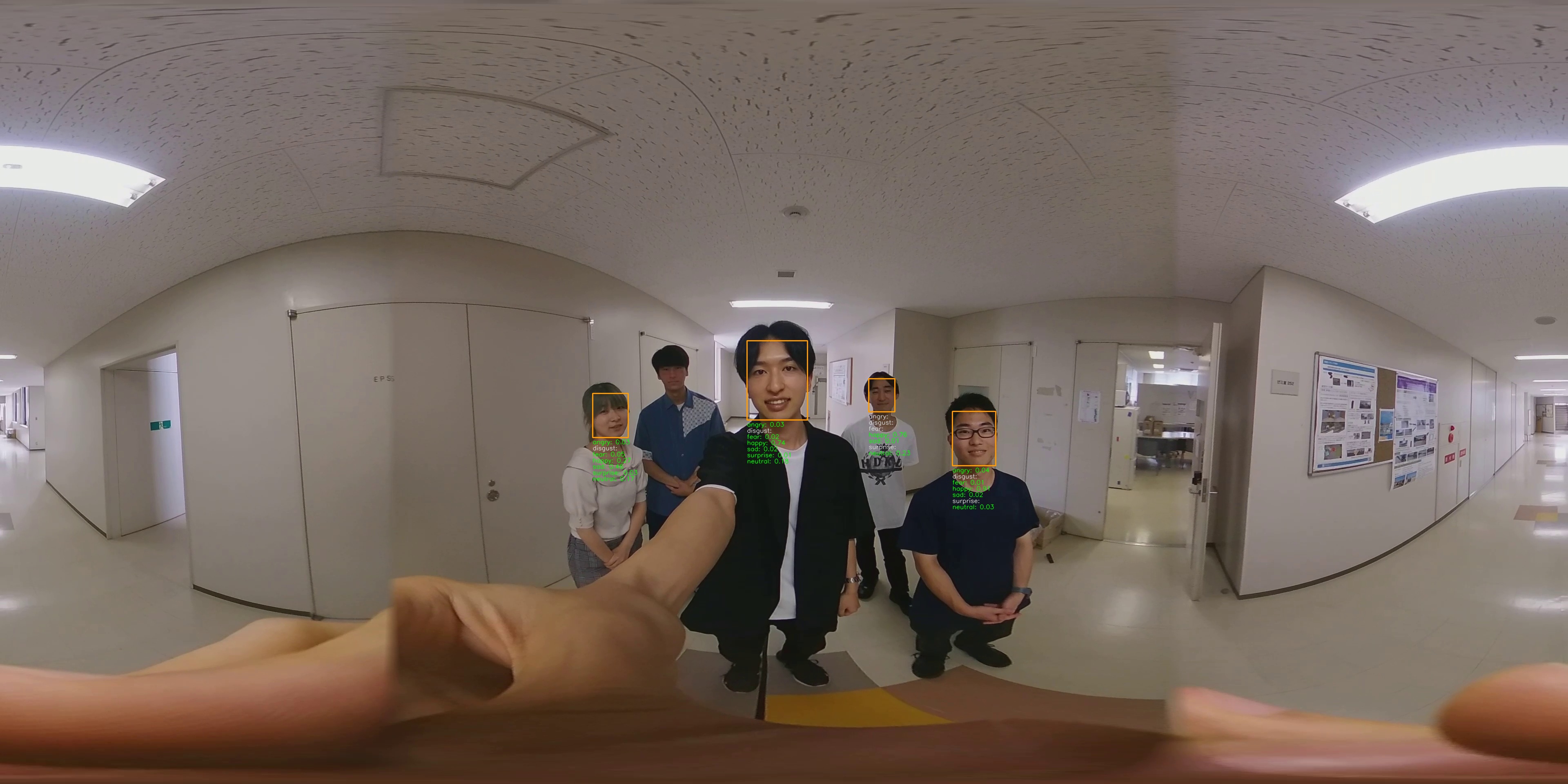
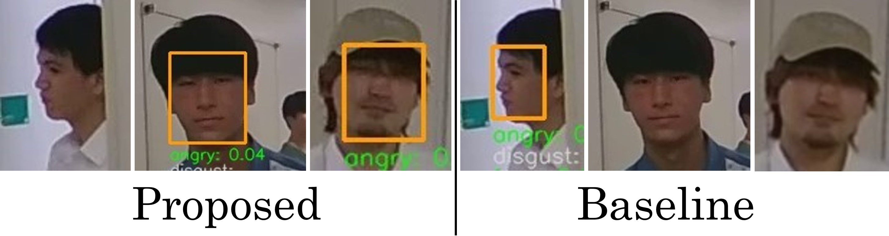
The proposed method detects faces from all frames in an omni-directional video. Here, We use MTCNN[20] (Multi-task Cascaded Convolutional Neural Networks). Figure 1(a) shows an example of face detection, in which the face detection is successful. However, objects other than faces such as keyboards and clocks can also be falsely detected as shown in Figs. 1(b)(c)(d). In addition, MTCNN often fails to detect faces as shown in Fig. 2. This may be caused by various factors such as brightness, hair, and hats.
To reduce the false detection, assuming that persons to be photographed are within approximately 0.3 to 1.5 meters from the camera as mentioned above, we set the minimum lengths for one side of the bounding box. This reduces the number of false detections such as the small bounding boxes shown in Figs. 1(b)(c). However, since this alone does not completely prevent false detections, further methods to prevent false detections are necessary.


3.3.2 Eliminating False Detection Faces and Interpolating Undetected Faces
To further reduce the reduction of false detections and also interpolate undetected faces, we first calculate the center coordinates of the bounding boxes from the upper left coordinates, width and height of bounding boxes for all the detected faces in all the frames. Second, we cluster all the center coordinates of bounding boxes using Mean Shift method [7]. Third, if the ratio of the number of elements in a class to the total number of frames is below a certain threshold , the bounding boxes in the class are deleted as false detection. In addition, we set the maximum length of one side of the bounding box and if the ratio of the number of elements in a class that have large regions as shown in Fig. 1(d) is more than , we eliminate the class. Finally, if an element in a remaining class is not present in a certain frame, a bounding box is generated in that frame using the mean coordinates and the mean width and height of the bounding boxes in the class. This allows undetected faces to be interpolated. The face detection results with false detection eliminated and undetected faces interpolated are used for the next facial expression recognition.
3.3.3 Facial Expression Recognition and Extraction of a Frame
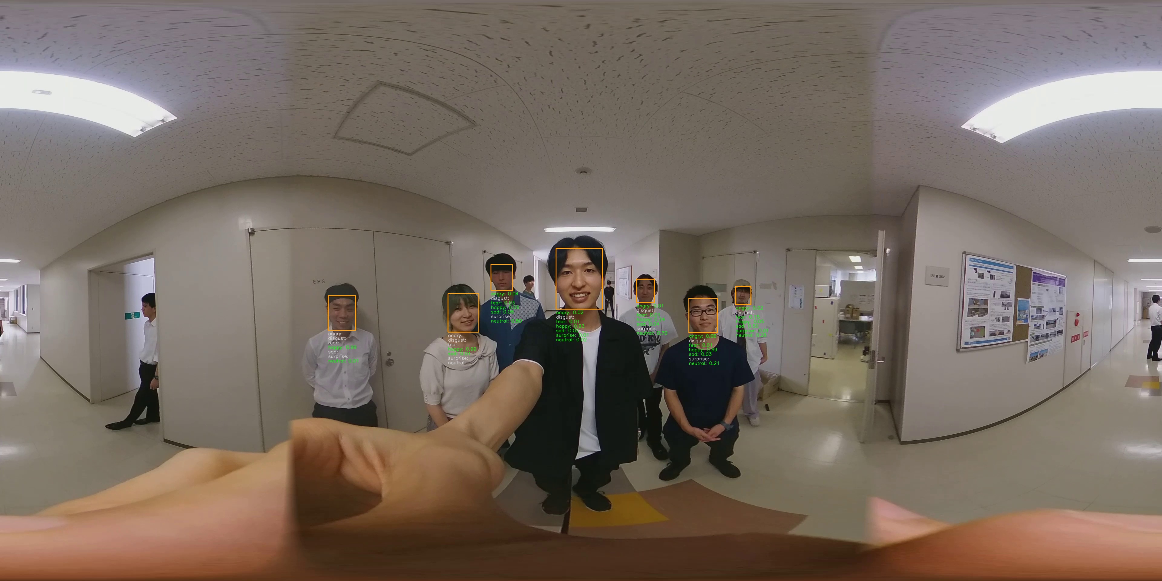
The proposed method applies FER (Face Emotion Recognizer)[17], which recognizes the facial expressions in seven categories: angry, disgust, fear, happy, sad, surprise and neutral. Based on the recognition results, the frame with the highest value is extracted from the omni-directional video using Eq. (1).
| (1) |
where and represent the mean and variance of the happiness expression values of all the detected faces in a frame and is a coefficient. The overall happiness value defined in Eq. (1) is calculated for each frame and the frame with the highest is extracted. In this study, we define happiness as the mean minus the variance, based on the idea that it would be ideal if everyone’s facial expressions were as uniform as possible.
3.4 Transformation to Perspective Projection Image
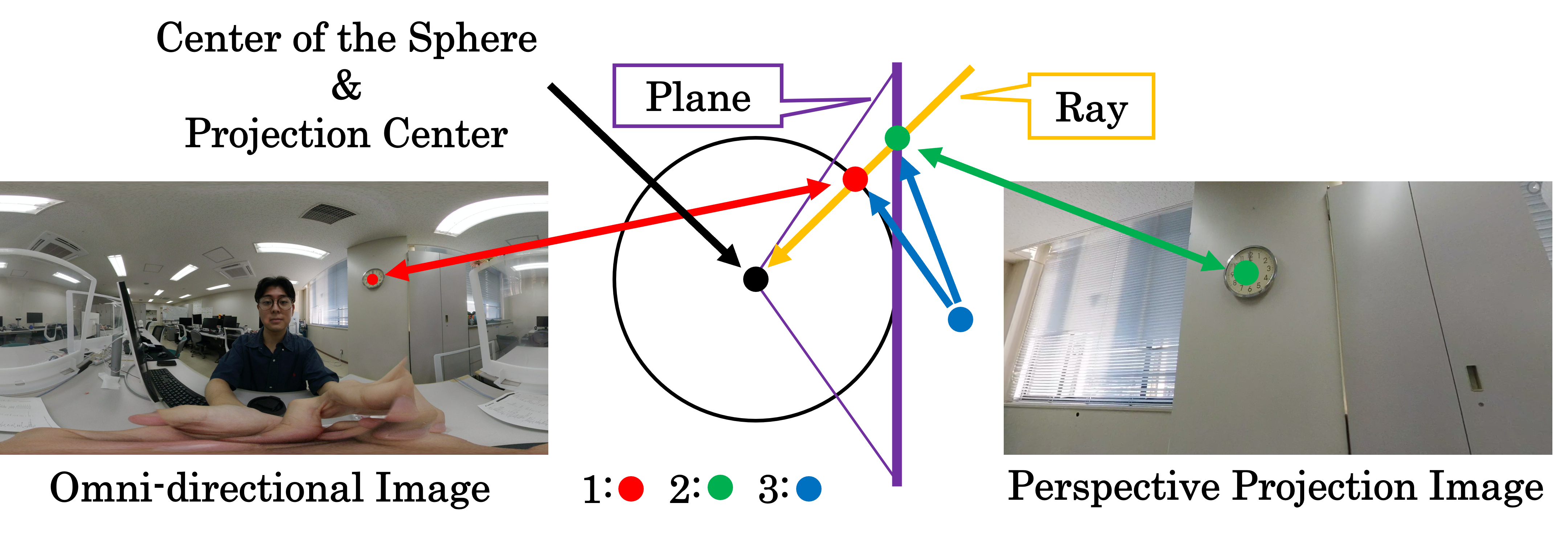
The proposed method transforms the omni-directional frame with the highest to a perspective projection image in which all the participants are in the angle of view. Figure 3 shows the relationships for the transformation. The transformation from an omni-directional image to a perspective projection image is obtained by considering the following three relationships 1, 2, and 3.
-
1.
A coordinate in an omni-directional image and a 3D position of a sphere
-
2.
A coordinate in a perspective projection image and a 3D position of a plane
-
3.
3D positions of a sphere and a plane through which the same ray passes
In addition, according to the positions of the photographed faces, the proposed method determines the center of the perspective projection image and the angle of view. We describe each relationship in detail below.
3.4.1 Relationship between Coordinate in Omni-directional Image and 3D Position of Sphere
Coordinates in an omni-directional image with equirectangular projection are corresponding to and , which are angles around and from Z-axis connecting the top and bottom of the sphere, respectively. Given that and denote the vertical and horizontal lengths of the omni-directional image, respectively, coordinates of the omni-directional image can be expressed using angles and as follows:
| (2) |
3.4.2 Relationship between Coordinate in Perspective Projection Image and 3D Position of Plane
Figure 5 shows the 3D position of the plane, which is corresponding to a perspective projection image, tangent to the sphere. The plane consists of the center position , and two orthogonal unit vectors and . They respectively become the center of the perspective projection image, and horizontal and vertical axes. In this study, , and are defined so that the upward direction of the image becomes that of the real world as follows:
| (3) |
where and are angles around and from Z-axis connecting the top and bottom of the sphere, respectively.
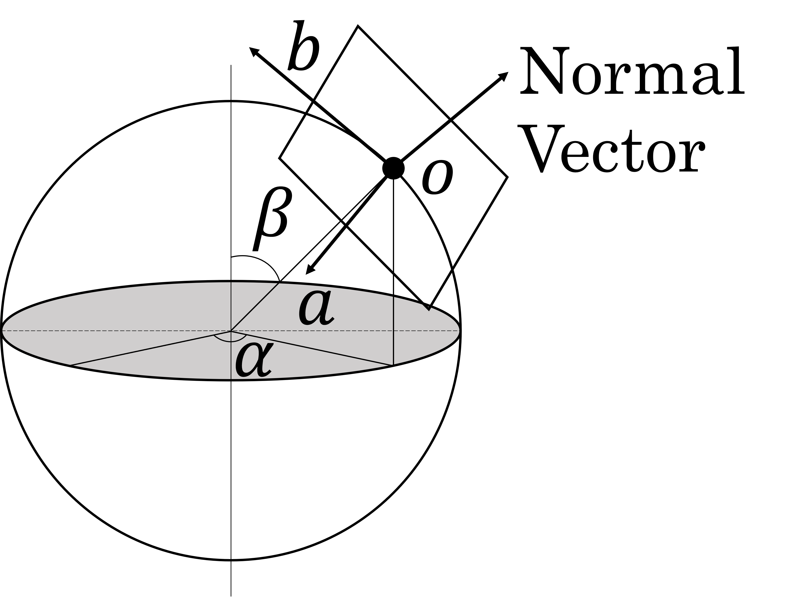

Figure 5 shows the relationship between a coordinate in a perspective projection image and the 3D position on the plane. The left and right figures in Fig. 5 represents a perspective projection image with height and width , and a 3D plane with height and width , respectively. In this case, the 3D position on the plane is represented using parameter as follows:
| (4) |
From Fig. 5 and Eq.(4), the relationship between the coordinate in the perspective projection image and is expressed by a translation and scaling matrix as follows.
| (5) |
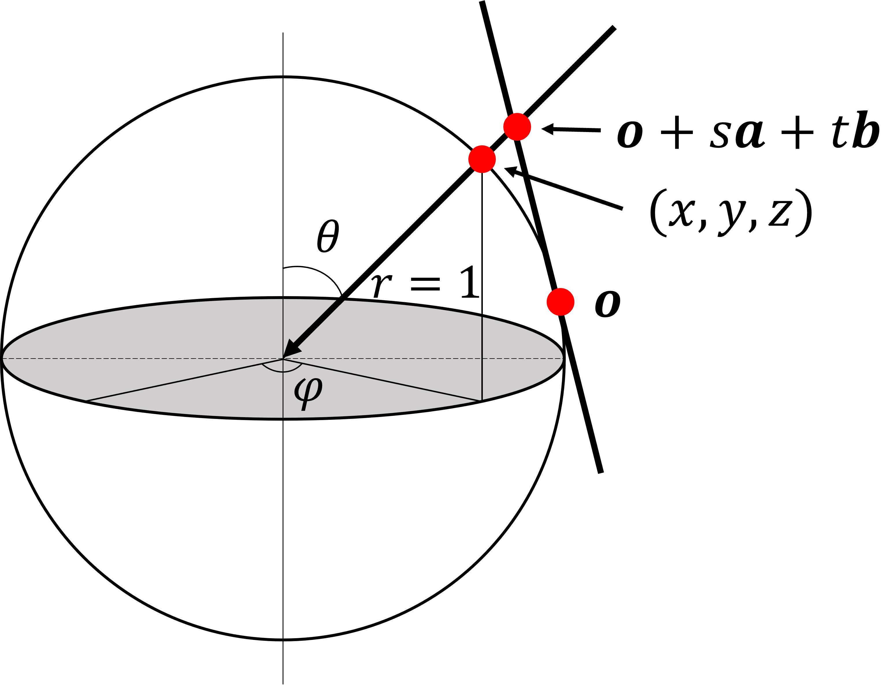
3.4.3 Relationship between 3D Positions of Sphere and Plane through which the Same Ray Passes
Figure 6 shows the relationship between points on the sphere and the plane where the same ray passes. Here, since the line passing through the point on the sphere and the center of the sphere intersects the plane, the relationship can be expressed with parameter as follows:
| (6) |
From the above Eqs. (2), (5) and (6), the coordinates in the perspective projection image can be mapped to the coordinates in the omnidirectional image to generate the perspective projection image. Here, it is necessary to find the center of the plane and the lengths and of the edges of the plane, which are corresponding to the center and the view angle of the perspective projection image so that the all the participants photographed are within the image.
3.4.4 Determination of the most left, right, top and bottom faces
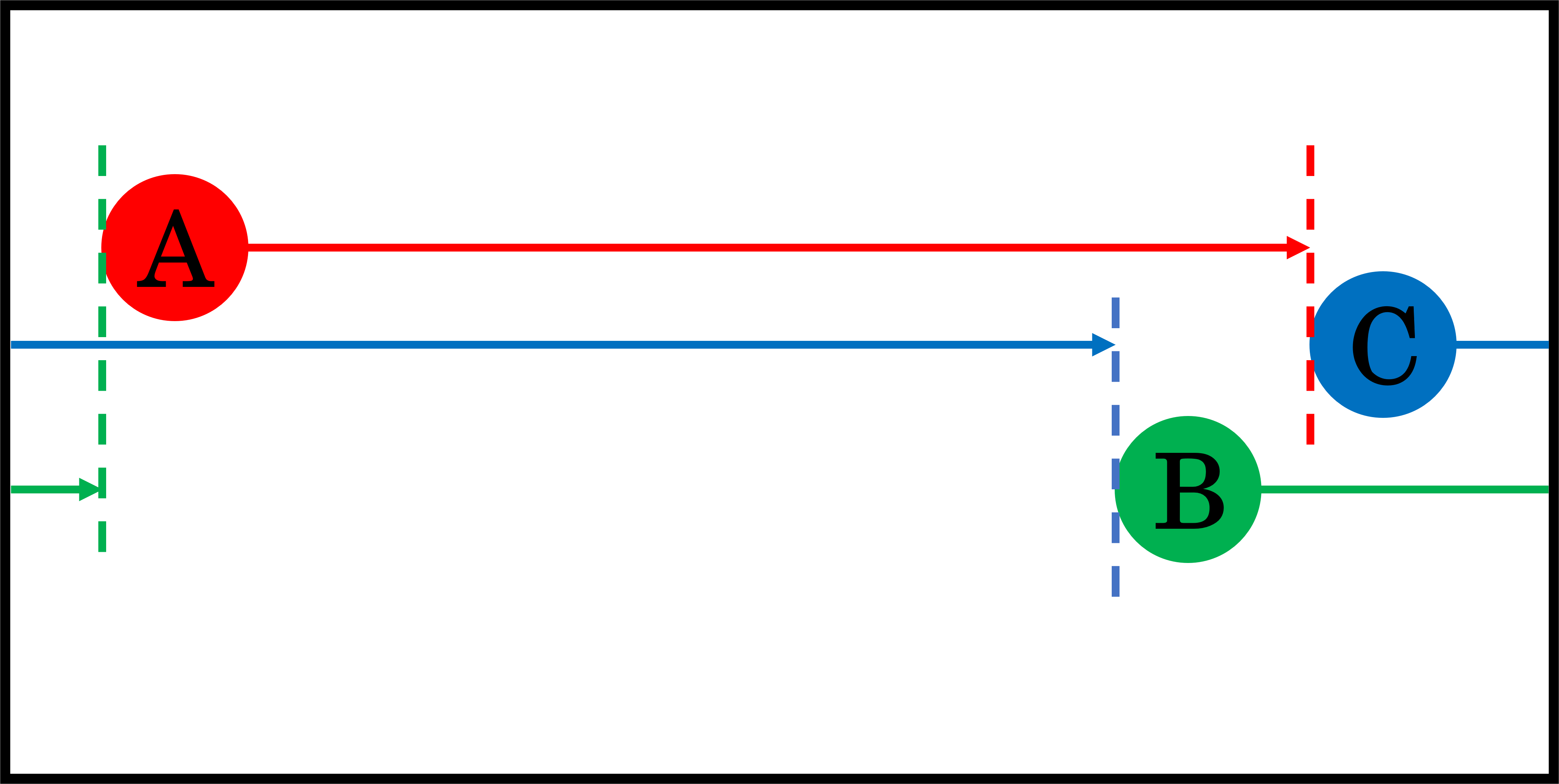
This study deals with omni-directional images in which the left and right edges of the images are connected. For this reason, the left and right positions of the faces in the omni-directional image do not necessarily correspond to their actual positions. Therefore, the left-most and right-most faces that appear in the perspective projection image are determined.
The proposed method calculates the distance from a face to the face with the longest distance from it in the positive direction of the x-axis of the omni-directional image. This is done for all faces, and the pair of faces with the shortest distance is extracted as the left face and the right face. Figure 7 illustrates an example in which A, B, and C represent three faces. First, if we consider A to be the left-most face and look for the face farthest to the left in the positive direction of the x-axis, we find C and calculate the distance between A and C. The same process is performed when B and C are considered the left-most faces. Next, the method finds the shortest distance. In the case of Fig. 7, B and A are the leftmost and the rightmost faces, respectively. As for the most top and bottom faces, we simply find the faces with the smallest and largest y-coordinates.
3.4.5 Calculation of Center on Perspective Projection Image
The proposed method calculates 3D coordinate on the plane, which is corresponding to the center of the perspective projection image. Specifically, we obtain the mean of the x-coordinates of the bounding box centers of the most left and right faces, and the mean of the y-coordinates of the bounding box centers of the most top and bottom faces. Note that the average of x is calculated considering only in the positive direction of the x-axis. Using the equations mentioned above, we transform x and y coordinates into angles to obtain 3D position .
3.4.6 Calculation of Angle of View of Perspective Projection Image
Since the vertical and horizontal lengths and of the 3D plane shown in Fig. 5 determine the angle of view of the perspective projection image, is calculated from the coordinates of the faces. Specifically, and are obtained from the coordinates of the corners of all bounding boxes using Eqs (2) and (6), and the maximum absolute values of and are obtained. Since and are unit vectors, doubling and yields an angle of view that includes all the faces. However, as shown in Fig. 1(a), the bounding box does not include the hair area. Therefore, by adding offset , and are determined as follows:
| (7) |
4 Experiments and Discussions
To demonstrate the effectiveness of the proposed method, we performed comparison experiments with a baseline method. For the baseline method, we used the default settings of MTCNN, i.e., the minimum value of one side of the bounding box for face detection is 20 pixels and the maximum value is not fixed. To extract the frame with the highest from all frames, the baseline method did not eliminate false detections or undetections, but simply extracted the frames in which the number of faces detected in a frame was the mode throughout all frames as a mechanism for eliminating false detections and undetections instead, and extracted the frame with the highest from the frames.
For the experiments, we used five types of omni-directional videos ( pixels) with different conditions, as shown in Table 5, and performed three types of validation. Experiment 1 is for validation of happy values, Experiments 2 and 3 are for validation of false detections, and Experiments 4 and 5 are for validation of undetections. These experiments were conducted by sighted people, not visually impaired people, and we empirically set the parameters of the proposed method as shown in Table 5.
Table 5 shows the experimental results of and of perspective projection images. Table 5 shows the experimental results for detection by the proposed method, and Table 5 shows the experimental results for detection by the baseline method. In the following, we discuss the three types of validation in turn.
| Expt. | No. of participants | No. of unrelated persons |
| 1 | 6 | 5 |
| 2 | 3 | 0 |
| 3 | 2 | 1 |
| 4 | 5 | 0 |
| 5 | 7 | 4 |
| Minumum length of bounding box | 50 pixels |
| Maximum length of bounding box | 250 pixels |
| Threshold for eliminating false detections | 25 % |
| Coefficient for happy value | 1 |
| Offset for perspective projection image | 0.3 |
| Proposed | Baseline | |||
|---|---|---|---|---|
| Expt. | ||||
| 1 | 0.458 | 0.400 | ||
| 2 | 0.895 | 0.648 | ||
| 3 | 0.309 | 0.155 | ||
| 4 | 0.483 | 0.612 | ||
| 5 | 0.402 | 0.491 | ||
| Expt. | (a) | (b) | (c) | (d) | (e) |
|---|---|---|---|---|---|
| 1 | 51 | 6 | 7 | 1 | 32 |
| 2 | 143 | 3 | 7 | 32 | 10 |
| 3 | 152 | 2 | 2 | 0 | 0 |
| 4 | 41 | 5 | 5 | 0 | 32 |
| 5 | 35 | 7 | 8 | 1 | 30 |
| Expt. | (a) | (b) | (c) | (d) | (e) | (f) | (g) | (h) |
|---|---|---|---|---|---|---|---|---|
| 1 | 51 | 6 | 19 | 0.372 | 31 | 38 | 5 | 0.098 |
| 2 | 143 | 4 | 52 | 0.363 | 101 | 2 | 41 | 0.286 |
| 3 | 152 | 3 | 108 | 0.710 | 147 | 2 | 5 | 0.032 |
| 4 | 41 | 4 | 25 | 0.609 | 1 | 39 | 2 | 0.048 |
| 5 | 35 | 6 | 13 | 0.371 | 34 | 32 | 0 | 0.000 |
4.1 Validation on Happiness Values
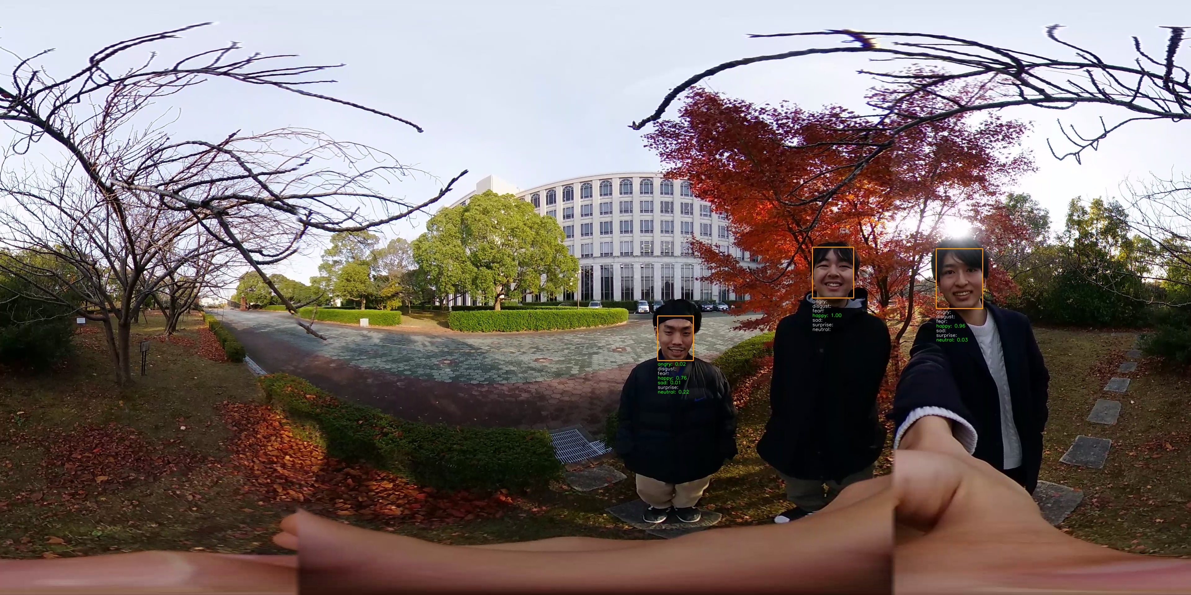
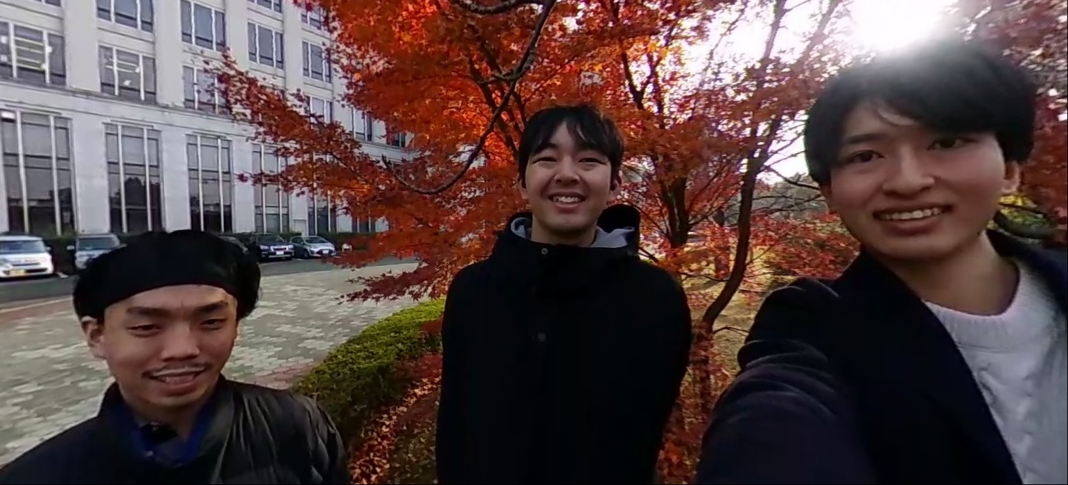
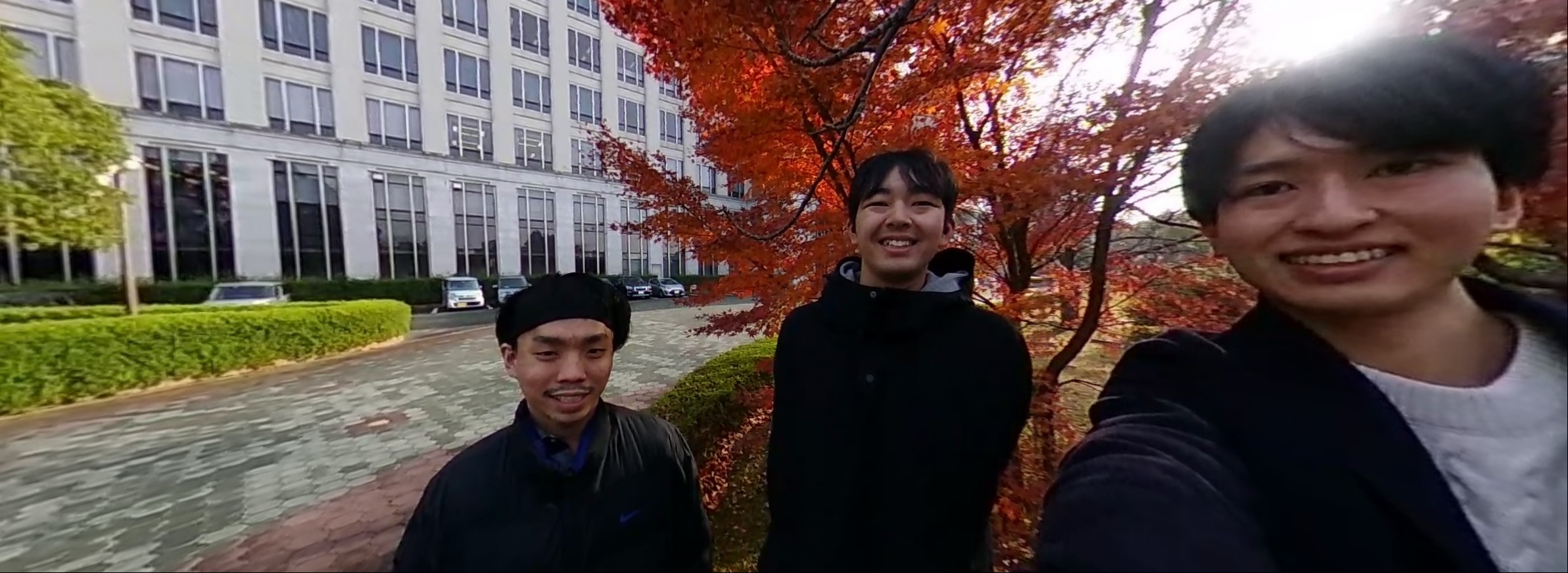
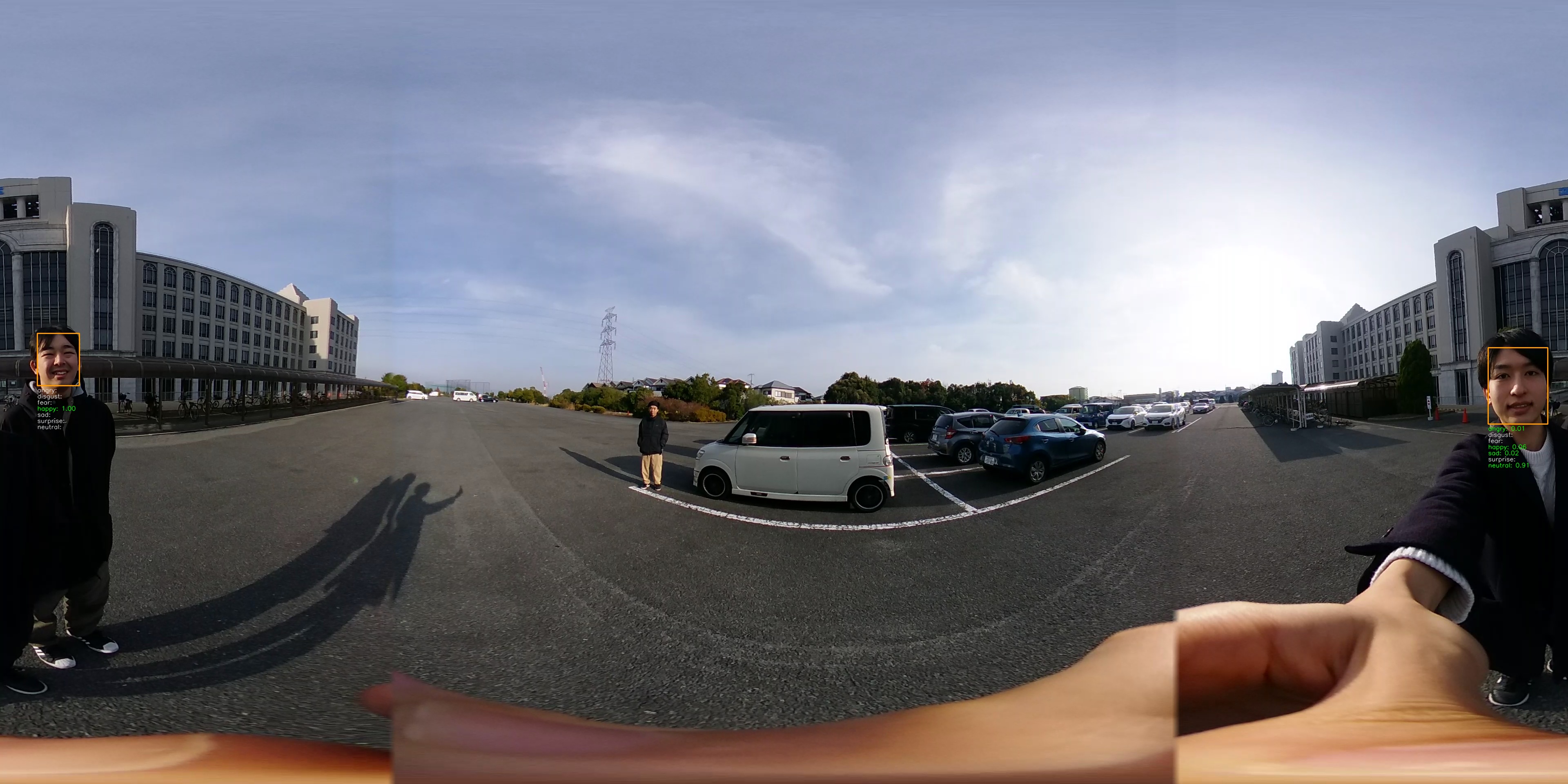
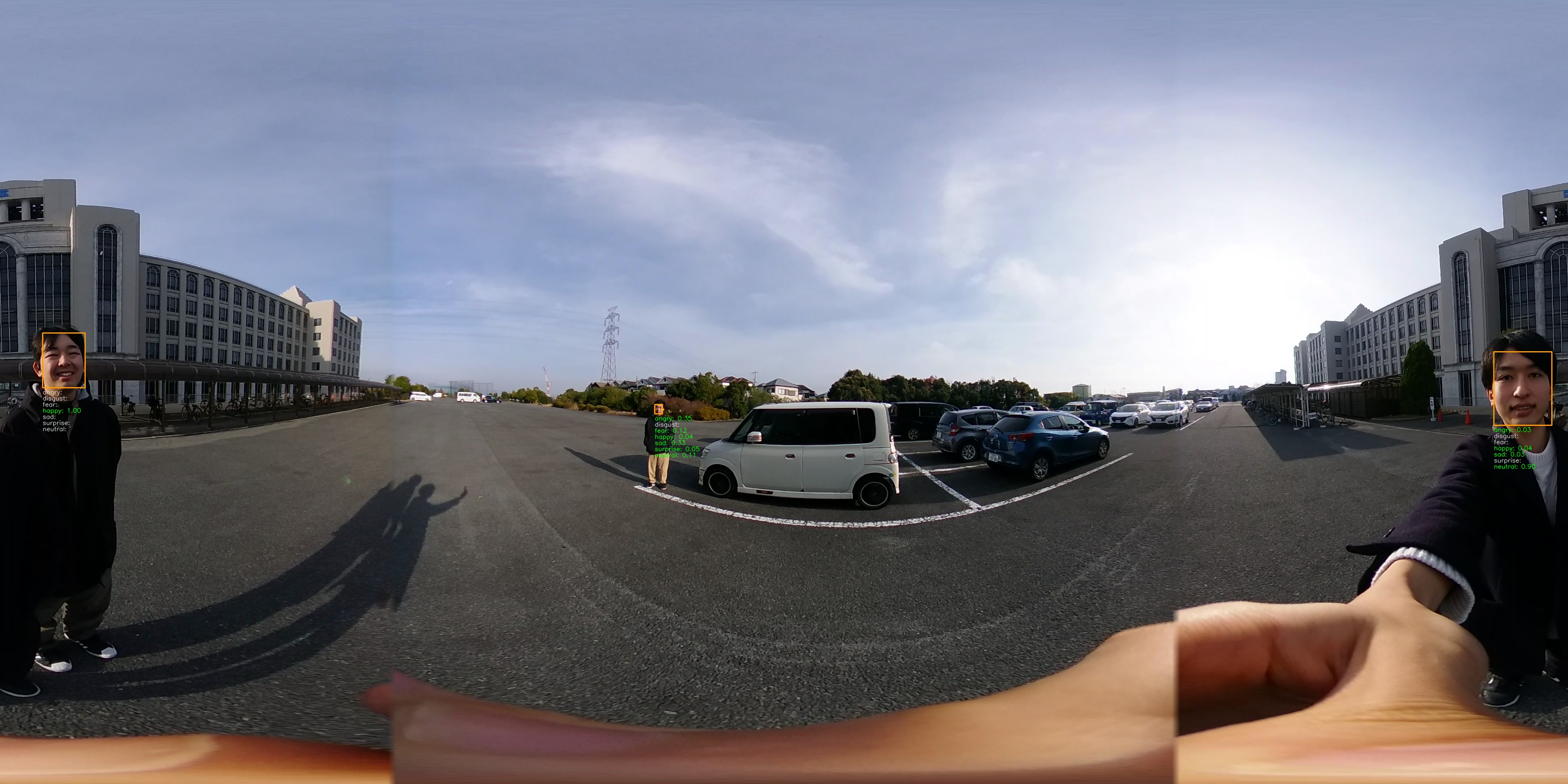
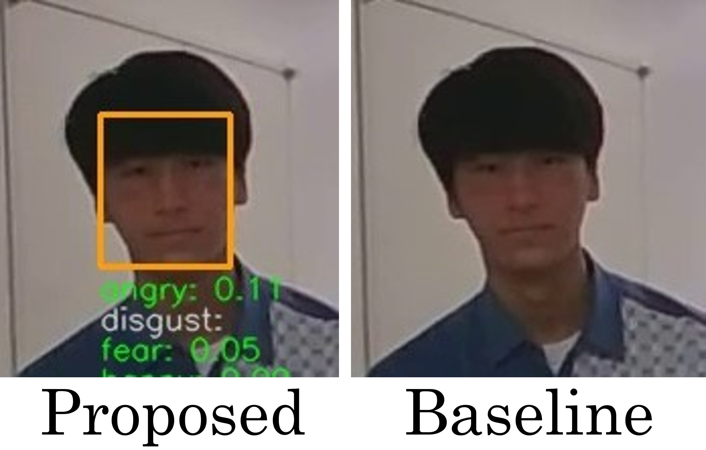
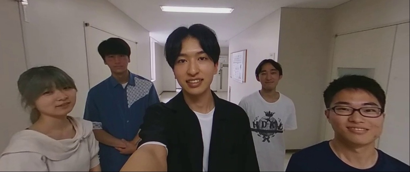
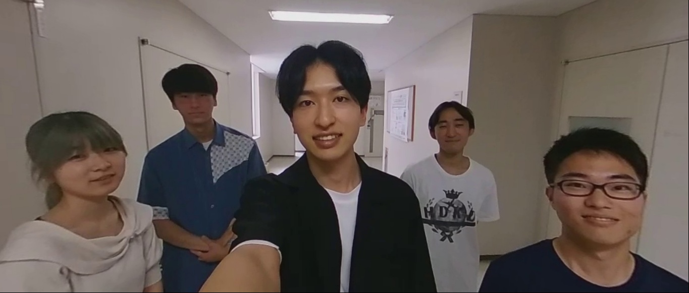
In Experiment 1, using the scene where six people are the photographed participants and four people are not related, we validate whether the proposed method can extract frames with higher than the baseline method. Figures 8(a) and (b) show the omni-directional frames with the highest extracted by the proposed method and the baseline method, respectively. Figures 8(d) and (e) are the perspective projection images generated from Figs. 8(a) and (b), and of the images by the proposed and baseline methods are 0.458 and 0.400, respectively, indicating that the proposed method is 0.058 higher. This is because the proposed method was able to compute for all the frames by setting the upper and lower sizes of the bounding box and eliminating false detections and interpolating undetected participants. On the other hand, for the baseline method, only 37.2% of all frames had a mode, as shown in Table 5. For example, as shown in Figs. 8(c) and (f), in the frame extracted by the proposed method, an unrelated person in the distance was detected by the baseline method, and this frame was not extracted because the number of detections is seven.


4.2 Validation on false detection elimination
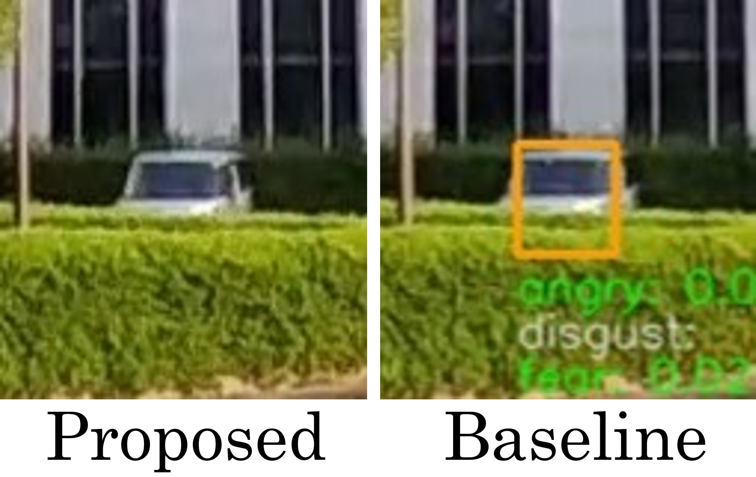
In Experiments 2 and 3, we validate whether the elimination of false detections by the proposed method is effective. First, in Experiment 2, although the number of photographed participants is three, the mode by the baseline method is four as shown in Table 5. This resulted in extracting the frame with the highest (Fig. 10(b)), which contains the false detection car shown on the right side of Fig. 10(c), and generating the perspective projection image with unnecessarily wide angle of view by the baseline method shown in Fig. 10(e). Also, is calculated as if the car is a face. Such a happiness value is not appropriate for selecting a frame.
In contrast, the results of the proposed method shown in Fig. 10(a) and the left figure in Fig. 10(c) and 10(d) show that the false detection of the car is eliminated and the perspective projection image contains only the participants. Specifically, in the procedure of the proposed method, the mean shift classifies the bounding boxes into seven classes, and threshold for the ratio of detections eliminated four types of false detections, which occurred in 32 frames, as shown in Table 5. As a result, three classes remained, which are number of participants.
Next, we describe Experiment 3, in which the number of people photographed is two and the number of unrelated persons is one. The baseline method extracted the frame with the highest (Fig. 10(b)), in which an unrelated person about four meters away from the camera was detected, as shown on the right side of Fig. 10(c). In this case, the angle of view of the perspective projection image that includes the three people becomes considerably larger, and the texture near the edges of the image is significantly stretched as shown in Fig. 10(e), which does not have proper visibility.
On the other hand, the results of the proposed method shown in Figs. 10(a), 10(d) and the left of 10(c) show that the false detection was eliminated and that only the target participants appear in the perspective projection images. Since the elimination of the false detection in this case is due to the setting of the minimum size of bounding boxes, we confirmed that such setting is effective. From the results, we can say that the proposed method of eliminating false detections by the mean shift clustering is more effective than the baseline method using the mode to generate perspective projection images in which only the photographed participants appear.


4.3 Validation on interpolation of Undetected Faces
In Experiments 4 and 5, we validate whether the interpolation of undetected faces is effective. First, let us start with Experiment 4, in which the number of participants is five. The baseline method extracted the frame with the highest (Fig. 12(b)), and output Fig. 12(e), excluding undetected persons, as shown on the right side of Fig. 12(c). In this scene, the detection accuracy of the some participants by MTCNN was poor, and the mode throughout all the frame is four, as shown in Table 5. Also, all the five participants were detected in only two frames, indicating that the baseline method cannot appropriately extract the frame with the highest for all the participants.
In contrast, the results of the proposed method shown in Figs. 12(a) and (d) and the left of Fig. 12(c) show that the proposed method interpolated undetected faces. As shown in Table 5, although the proposed method still failed to detect faces in 32 frames, since each of the five participants was detected in more than 25% of all the frames, the mean value of the bounding boxes for each person could be used to interpolate the undetected persons.
Next, we describe Experiment 5, in which the number of people photographed is seven and the number of unrelated persons is four. The baseline method extracted the frame with the highest (Fig. 12(b)), which has one false detection and two undetected, as shown in the three images on the right side of Fig. 12(d). In this case, the mode is six as shown in Table 5, which indicates that the persons detected in each frame differs depending on false detections and undetections. In addition, since the falsely detected person was located further away from the target participants, the calculated i.e., the angle of view, became larger as shown in Table 5, resulting in failing to generate an appropriately visible image.
In contrast, the results of the proposed method shown in Figs. 12(a), (c) and the left three images in Fig. 12(d) show that the false detection was eliminated and the undetected persons were interpolated. As a result, only the participants appear in the perspective projection images. As shown in Table 5, even though some of participants were undetected in 30 frames in the proposed method, the mean-shift clustering determined the number of classes appropriate for the number of participants, and all undetected faces were interpolated. From these results, we confirmed that the proposed method with undetected interpolation is effective because it can calculate for all the photographed participants in all the frames.
5 Conclusion
In this study, we proposed a method that enables to take selfies with multiple people using an omni-directional camera. The proposed method succeeded in eliminating false detections and interpolating undetected faces to extract the frame with the happiest expressions of all the photographed participants from all the frames, and generating a perspective projection image in which all the participants are present. In the experiments, we compared the proposed method with the baseline method to demonstrate its effectiveness. Future work includes the determination of optical parameters for enhancing false detection elimination and undetected interpolation.
References
- [1] Be my eyes. https://www.bemyeyes.com/, (Accessed on 24/11/2023)
- [2] Envision ai. https://apps.apple.com/jp/app/envision-ai/id1268632314, (Accessed on 24/11/2023)
- [3] Orcam myeye 2. https://www.orcam.com/en/myeye2/, (Accessed on 24/11/2023)
- [4] Taptapsee. https://taptapseeapp.com/, (Accessed on 24/11/2023)
- [5] Balata, J., Mikovec, Z., Neoproud, L.: Blindcamera: Central and golden-ratio composition for blind photographers. In: Proceedings of the Mulitimedia, Interaction, Design and Innnovation, pp. 1–8 (2015)
- [6] Bigham, J.P., Jayant, C., Ji, H., Little, G., Miller, A., Miller, R.C., Miller, R., Tatarowicz, A., White, B., White, S., et al.: Vizwiz: nearly real-time answers to visual questions. In: Proceedings of the 23nd annual ACM Symposium on User Interface Software and Technology. pp. 333–342 (2010)
- [7] Comaniciu, D., Meer, P.: Mean shift: A robust approach toward feature space analysis. IEEE Transactions on Pattern Analysis and Machine Intelligence 24(5), 603–619 (2002)
- [8] Cutter, M.P., Manduchi, R.: Towards mobile ocr: How to take a good picture of a document without sight. In: Proceedings of the 2015 ACM Symposium on Document Engineering. pp. 75–84 (2015)
- [9] Gonzalez Penuela, R.E., Vermette, P., Yan, Z., Zhang, C., Vertanen, K., Azenkot, S.: Understanding how people with visual impairments take selfies: Experiences and challenges. In: Proceedings of the 24th International ACM SIGACCESS Conference on Computers and Accessibility. pp. 1–4 (2022)
- [10] Iwamura, M., Hirabayashi, N., Cheng, Z., Minatani, K., Kise, K.: Visphoto: photography for people with visual impairment as post-production of omni-directional camera image. In: Extended Abstracts of the 2020 CHI Conference on Human Factors in Computing Systems. pp. 1–9 (2020)
- [11] Jayant, C., Ji, H., White, S., Bigham, J.P.: Supporting blind photography. In: Proceedings of the 13th International ACM SIGACCESS Conference on Computers and Accessibility. pp. 203–210 (2011)
- [12] Jokela, T., Ojala, J., Väänänen, K.: How people use 360-degree cameras. In: Proceedings of the 18th International Conference on Mobile and Ubiquitous Multimedia. pp. 1–10 (2019)
- [13] Kacorri, H., Kitani, K.M., Bigham, J.P., Asakawa, C.: People with visual impairment training personal object recognizers: Feasibility and challenges. In: Proceedings of the 2017 CHI Conference on Human Factors in Computing Systems. pp. 5839–5849 (2017)
- [14] Kutiyanawala, A., Kulyukin, V., Nicholson, J.: Teleassistance in accessible shopping for the blind. In: Proceedings on the International Conference on Internet Computing. p. 1 (2011)
- [15] Meijer, P.: The voice - new frontiers in sensory substitution. https://www.seeingwithsound.com/, (Accessed on 24/11/2023)
- [16] Obata, K., Nakamura, Y., Chen, L., Augeri, J.: Asynchronous co-eating through video message exchange: Support for making video messages. In: Proceedings of Cross-Cultural Design. Applications in Health, Learning, Communication, and Creativity. pp. 338–348 (2020)
- [17] Shenk, J., CG, A., Arriaga, O., Owlwasrowk: justinshenk/fer: Zenodo (Sep 2021), https://doi.org/10.5281/zenodo.5362356, (Accessed on 18/7/2023)
- [18] Vázquez, M., Steinfeld, A.: An assisted photography framework to help visually impaired users properly aim a camera. ACM Transactions on Computer-Human Interaction 21(5), 1–29 (2014)
- [19] White, S., Ji, H., Bigham, J.P.: Easysnap: real-time audio feedback for blind photography. In: Adjunct Proceedings of the 23nd annual ACM Symposium on User Interface Software and Technology. pp. 409–410 (2010)
- [20] Zhang, K., Zhang, Z., Li, Z., Qiao, Y.: Joint face detection and alignment using multitask cascaded convolutional networks. IEEE Signal Processing Letters 23(10), 1499–1503 (2016)