1.5pt
SeeBelow: Sub-dermal 3D Reconstruction of Tumors with Surgical Robotic Palpation and Tactile Exploration
Abstract
Surgical scene understanding in Robot-assisted Minimally Invasive Surgery (RMIS) is highly reliant on visual cues and lacks tactile perception. Force-modulated surgical palpation with tactile feedback is necessary for localization, geometry/depth estimation, and dexterous exploration of abnormal stiff inclusions in subsurface tissue layers. Prior works explored surface-level tissue abnormalities or single layered tissue-tumor embeddings with more than 300 palpations for dense 2D stiffness mapping. Our approach focuses on 3D reconstructions of sub-dermal tumor surface profiles in multi-layered tissue (skin-fat-muscle) using a visually-guided novel tactile navigation policy. A robotic palpation probe with tri-axial force sensing was leveraged for tactile exploration of the phantom. From a surface mesh of the surgical region initialized from a depth camera, the policy explores a surgeon’s region of interest through palpation, sampled from bayesian optimization. Each palpation includes contour following using a contact-safe impedance controller to trace the sub-dermal tumor geometry, until the underlying tumor-tissue boundary is reached. Projections of these contour following palpation trajectories allows 3D reconstruction of the subdermal tumor surface profile in less than 100 palpations. Our approach generates high-fidelity 3D surface reconstructions of rigid tumor embeddings in tissue layers with isotropic elasticities, although soft tumor geometries are yet to be explored. For more details, please refer to our open-source codebase111https://github.com/raghavauppuluri13/seebelow and project website222https://raghavauppuluri13.github.io/seebelow.github.io/.
I Introduction
Surgical palpation is a widely performed examination technique to assess the location and geometry of tissue anomalies during laparoscopic or minimally invasive surgery (MIS). Although prior knowledge about surgical tissue conditions (tumors, cysts, lesions, nodules, etc) are available preoperatively from CT, MRI or Ultrasound scan-based medical imaging modalities, the intraoperative surgical scene understanding in robot-assisted minimally invasive surgery (RMIS) is highly challenging. Localization of soft tissue conditions in RMIS is immensely impacted by variances in tissue compliance, peripheral tissue intrusions along the navigating direction and visual occlusions from body fluids. These factors assert spatial uncertainties in graphical rendering of anatomical landmarks as compared to referenced medical images. Surgical palpation of the target anatomy with kinesthetic feedback from surgeon’s fingers, as used in conventional open surgery, better assists in the surgical scene understanding and tissue manipulation which is often lost in RMIS. The deficiency of tactile perception in RMIS can be compensated with robotic surgical palpation probes which will add tactile information about the target tissue stiffness and compliance. This information can demarcate boundaries of underlying tissue abnormalities while reconstructing the 3D surface profiles of subdermal stiffer tumors.
II Related Work
Previous works investigated different force sensing modalities[1, 2, 3, 4] to study soft compliant surface contact interactions [5, 6] and force sensing uncertainty compensations [7] for soft tissue palpation and exploration. Recent advancements in commercial surgical platforms[8, 9] achieved amazing feats [10] in execution of semi-autonomous surgical procedures [11].
Nonetheless, adequate robotic surgical autonomy might be reached with augmenting the perception of robotic touch with surgical haptics[12] and force modulated tactile imaging [13, 14, 15]. A complimentary approach of facilitating high resolution robotic touch with HD in-vivo stereo-vision for laparoscopic robotic surgery will imitate a surgeon’s hand-eye coordination-based dexterity in precise form factor to better navigate and map intricate anatomical structures of the tissue. Autonomous robotic probing of tumor tissues with active area search [16] have found promising results optimizing over a Gaussian Process (GP) regression model built from discrete palpations measuring stiffness of random indentation points. Gaussian Process regression (GP) [17] and Bayesian Optimization (BO) [18] has been effective in reducing global search space minimizing computation cost and palpation time for indentation based probing to locate stiff inclusion in compliant surfaces. In RMIS, the robotic laparoscopic probes are kinematically constrained within the intraoperative space. Therefore surgical planning needs safe contact-rich manipulations applying optimal forces to the target tissues and their underlying layers which have unmodelled characteristics (e.g varying contact friction, slip, stiffness, and damping).
Soft tissue scanning is extensively practiced in orthopaedic manual therapy to assess pain in chronic musculoskeletal pain conditions. In context, classified force-motion patterns [19] of quantifiable soft tissue manipulations[20] using a handheld localized [21] and dispersive force-motion applicators [22, 23] are studied for clinical manual therapy treatment assessments. Palpation techniques [24] adopted from handheld instrumented soft tissue manipulations[25, 26] can form the basis of dynamic robotic tactile probing for trajectory optimized geometry estimation of sub-dermal surgical tumor localization.
TIn context, our prior work incorporated finite element modeling and simulation of quasi-static robotic palpation [27] to investigate strain and deformations in underlying subsurface tissue layers due to the presence and absence of a stiff adipose sarcoma (tumor). Results revealed that presence of a stiffer tumor reduces strain distribution over peripheral tissue layers indicating negligible principal strains in layers underneath the tumor surface as evident from their deformation profiles. This study is an expansion of our prior work to investigate tactile exploration policy learning approaches of Robotic palpation for surgical scene localization, 3D surface reconstruction and graphical rendering of sub-dermal tumor geometry augmenting computer assisted surgery. The main contributions for developing such tactile navigation policies include:
-
•
A surgical scene initialization and registration pipeline comprising 3D point cloud generated surface mesh and its corresponding interpolated surface grid mapping.
-
•
Bayesian Optimization based palpation coordinate search on the interpolated surface grid locating optimal indentation points.
-
•
Tumor localization policy using subdermal tumor surface contour-following controller governed by impedance control for palpation trajectory generation.
The waypoints from these palpation trajectories are further used for tumor surface 3D reconstructions.

III System Setup
Anatomical tissue layers are viscoelastic in nature. Therefore, contact-based robotic tactile exploration engages examining a series of contact parameters (compressive and shear forces, angle of force application, deformation of the tissue and tooltip-tissue interacting friction) that are necessary to investigate for tissue exploration. To simplify our design of experiments, we embed 3D printed rigid tumors of different geometries into tissue layers of a surgical training phantom. A 7-DOF Franka-emika Panda collaborative robot arm with a custom designed end effector palpation probe, equipped with custom built force-motion-vision sensing was utilized in carrying out palpation experiments on the phantom (Mediarchitect) [28]. The end effector attachment was packaged with a tri-axial Load-cell (TechGihan Co. Ltd) and a 9 DOF Magnetic, Angular Rate and Gravity (MARG) inertial sensing unit (ICM20948, Invensense) to facilitate online force-motion sensing powered by a 32-bit NXP micro-controller. An externally mounted Depth Camera (Intel RealSense D415) served the eyes of the Robot Arm for mapping the external tissue surface point clouds of the phantom. The palpation probe includes a funnel-shaped tip with a smooth spherically contoured tissue interaction edge of 5mm diameter similar to RMIS probes for in-vivo tissue explorations. The surgical training phantom as shown in Fig.1 has a detachable superficial anatomy (Dermal and Adipose layer) with a fixed myofascial (Muscle) layer sitting on a rigid base encapsulated by a support frame. Tumors being stiffer than healthy tissues allowed us to 3D print three rigid tumor geometries (Hemisphere, Ellipsoid and Crescent) and screw them into the myofascial layer from the bottom while covering them by the detachable superficial tissue layers to complete the phantom assembly. Robot control policies were generated to navigate the visible curved surface contour of the dermal layer to localize and map the underlying invisible subdermal tumor geometries for 3D surface reconstruction and graphical rendering of their shapes using tactile explorations.

IV Methodology
The automatic tactile exploration policy control pipeline for generating contour following palpation trajectories are shown in Fig.2. This pipeline is further decomposed into surgical scene registration, optimal search planning, and online palpation with gravity compensated force calibration as illustrated below:
IV-A Surgical Scene Registration
In RMIS, a surgical scene acquired by the depth camera can often be complicated and can only be correctly understood by the surgeon. Therefore, our approach offers demarcating a target region of interest (ROI) using a bounding box, by the user (surgeon), reducing the search space. This allows the robot to optimally locate tumor coordinates for successive indentation based palpations. For registering the surgical scene, the raw surface point-cloud from the depth camera is post-processed, converted to a smooth 3D triangular surface mesh of the tissue phantom, and finally cropped into a user specified ROI. This ROI of the phantom’s surface mesh is enclosed in a bounding box for further interpolation into a 3D surface grid map as shown in Fig. 3 .

Given the objective to minimize palpations, discrete search in Cartesian Space can be computationally expensive. Additionally, the points from the 3D surface mesh are unstructured, nonuniform and scattered, leading to difficulty in sampling for search space optimization. Therefore a uniform 2D grid with sampling resolution is generated within the external bounds of X-Y plane (Fig. 3(b)) of the surface mesh. This 2D grid is interpolated to the scattered points in the 3D surface mesh using the cubic interpolation method generating a 3D surface grid map. Vertices of each grid cell corresponds to a point and normal on 3D surface mesh . The grid cells of this interpolated surface grid is further used in optimal search planning to determine palpation coordinates.


IV-B Optimal Search Planning
Random search of palpation points may affect the robustness of exploring the tissue surface leading to discretely probing the phantom without locating the tumor in minimal time. Therefore, optimal search planning was necessary to locate coordinates with higher stiffness values representing a tumor within a given probe displacement range. To achieve this we adopted searching palpation coordinates on the surface 2D grid with Gaussian Process regression and Bayesian Optimization.
IV-B1 Gaussian Process Regression
Gaussian processes (GP) are commonly used to model the stiffness distributions expanded over the total sample space of probed cells on the surface grid. The stiffness at each probed cell on the grid is represented as a random variable sampled from a gaussian distribution , where is the mean and is the variance involved, and is the stiffness measures observed as a random variable for successive indentations. GP regression, adopted from [16], makes predictions for next probed cell for maximum observed stiffness.
IV-B2 Bayesian Optimization
Bayesian optimization (BO) allows extracting the global maxima of a distribution function from its samples. Therefore probing at different coordinates on the surface grid produces a stiffness distribution sample space with stiffness for at least two or more indentations. BO selects the optimal stiffness state , using the posterior mean of the GP, which corresponds to grid cell that optimizes over an Expected Improvement (EI) objective function. For further details, mathematical expressions of this objective function are well elaborated in [16]. This is how the tumor coordinates are detected in the given search space, which allows BO to collect more samples around its vicinity to facilitate dense palpation for refined tumor surface reconstruction.
IV-C Force Calibration and Gravity Compensation
Gravity compensation is essential for calibration and accurate force estimation at the tip of the palpation probe. As force sensing from the Load Cell as well as force estimation from the Robot’s joint torques were utilized for tactile sensing, we included a two-fold gravity compensation method. The moment of inertia matrix of the robots end effector attachment, including its centre of mass were acquired from CAD. The mass of the attachment were determined from weighing the full assembly of the attachment. These parameters were fed into the Franka Panda’s Low level gravity compensation and state estimation algorithms to facilitate accurate force estimation at the tip from joint torques. Similarly gravity compensation was conducted for force calibration of the triaxial load cell eliminating force skewness due to tension exerted by the palpation tip. This is performed in two steps – (a) Load cell Z axis voltage offset shift compensation due to tension forces exerted by palpation tip attachment; and (b) Weight compensation of the tip using forward-inverse kinematics of the Load cell coordinate frames in three steps. The weight compensation is elaborated as:(i) Forward kinematics performed by transformation of the Load cell co-ordinates from Local to Inertial reference: , where is the rotation matrix of euclidean space in ZYX Euler combination and are Euler angles (Yaw, Pitch, Roll) computed from sensor fusion of accelerometer and gyroscope readings of the IMU sensor; (ii) Subtraction of the tip mass Newtons from the load-cell Z direction in the inertial frame by: ; and (iii) Finally inverse kinematics is used for transforming the Load-cell updated force values back to the local reference from the inertial reference by: . The robustness of this force calibration with gravity correction approach has been validated in handheld devices [22] of manual therapy. The Root mean squared value computed from serves as the load cell derived resultant reaction force acting at the tip of the palpation probe used in further computations.
IV-D Online Palpation
Our online palpation framework has two primitives: Discrete Probing to detect tumor coordinates on the Surface grid and Contour following along the tumor surface geometry to generate palpation trajectories.
IV-D1 Discrete Probing
Operational Space Controller (OSC) [29] facilitates safe generation of command joint torques providing a sufficient tradeoff between passivity and motion accuracy for contact-rich applications [30]. Therefore, OSC is utilized for moving and orienting the end-effector tip at the initial probing point on the surface grid cell for discrete probing based indentations. The axial direction of the tip is aligned along the surface normal of initial probing point acquired from the grid to surface map, as shown in Fig. 4 (a). This is followed by compressive indentation of the tissue along the surface normal directions to generate stiffness estimates using compressive reaction force component , and probe displacement shown in Fig. 4 (b), along the z axis of the load cell.
IV-D2 Stiffness Estimate
The external load cell derived forces as well as end-effector forces computed by the Robot’s joint torques were leveraged to compute stiffness estimates of each probed coordinate on the surface grid cell. The gravity corrected calibrated force vector was primarily utilised further in the development pipeline. Compressive force threshold across the surface indentation depth from skin to muscle layer was experimentally computed. The end-effector indentation will either approximate displacement from skin to tumor or displacement to muscle at the termination point from initial point for each probing coordinate’s component. The end-effector indentation depths are calculated from probe displacements opposite to the surface normals applying compressive reaction forces , where compressive force is a function of time . Stiffness estimates at each indentation is computed as: , which determines whether the indentation touches a tumor surface or a muscle layer. If the condition for indentation force and probe displacement is met, then the indentation confirms detection of a tumor coordinate, which needs to be succeeded by the contour following primitive.
IV-D3 Contour Following
Once a tumor coordinate is detected as a result of a discretely probed indentation, and the tip is in contact with the skin, the OSC switches to contact safe impedance controller. This impedance controller generates motions to trace sub-dermal surface profile of the tumor geometry until it reaches the tumor-muscle boundary for palpation trajectory generation.
To generate contour following controller targets, we empirically derived a simple, oscillatory motion path with minimal jerk for tracing the tumor surface contour until it reaches the tumor-muscle boundary in iterative time-steps, without getting stuck at each iteration.
| (1) |
where is a small finite pose change due to oscillatory motion to trace the tumor surface along (red) or (green) direction of the contour (Fig. 4(c)) while maintaining compressive indentation and contact with tissue surface. Additionally, is the amplitude of the oscillatory motion and is the time-step sampled at a frequency of . At every iteration the upstream controller targets a desired position , from current position where:
| (2) |
Contour following requires safe, contact-rich interactions with the tissue, while avoiding potential unsafe accelerations. The standard impedance control objective [31] explicitly modulates a commanded end-effector force to model contact rich interactions.
| (3) |
where is the commanded end-effector force opposite to direction (Fig. 4 (b)), following the principle of dynamic equation of motions by modelling a spring-damper equilibrium system with and being the damping coefficient and spring constant respectively. Here, is the desired pose and is the measured pose of the end-effector with pose error and velocity/twist error . This commanded interaction force objective is further transformed into joint torques
| (4) |
where is the robot Jacobian matrix, is the coriolis joint torques, while a bounded pose error limit is asserted to ensure safe interaction of the tissue-tip contact during contour following. This limits the commanded interaction forces withing an admissible range without damaging the tissue while maintaining optimal contact as described in [32]. The admissible interaction force , where is the controller period ).


The contour following impedance controller terminates when the indentation reaches the tumor-muscle boundary and meets the condition of indentation depth and indentation force as it indents the compliant muscle layer as shown in Fig. 4(c).
IV-E Palpation Trajectories
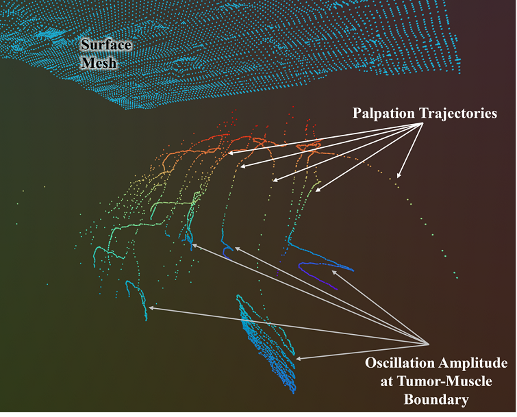
The pose extracted at every iteration time step are 3D plotted to generate the palpation trajectories of the contour following oscillatory motions. At the tumor-muscle boundary the compressive force condition switches from to , due to the compliance of the conforming muscle layer. Therefore a high amplitude of oscillatory motions are observed at the end of each palpation trajectory as shown in Fig. 5. Additionally, the pose error drastically increases exceeding the error limit and forcing the impedance controller to fail. An exception handling method resolves this limitation by adding timeout function which automatically terminates the contour following and transfers the control to OSC for probing next palpation points. The palpation trajectories generated from each contour following motions are projected into a 3D triangular surface mesh to 3D reconstruct the tumor geometry surface plots.
V Experiments and Results
Two different palpation approaches were adopted to test surface 3D reconstructions of tumor geometries. The first approach was discretely probed indentations of the cropped phantom surface with Bayesian Optimization (BO) or Random search (RS) without BO, both of which doesn’t involve palpation trajectories. While, the second approach involves BO or RS based probing for search space sampling to detect high stiffness points and then continuously tracing the stiffer geometry using contour following indentation path to generate palpation trajectories. For experimental convenience the embedded tumors were screwed into the muscle layer from the bottom, while the phantom assembly after integrating the top tissue layers were fixed to the base frame with an adhesive. This ensured eliminating all internal and external motions of the phantom and tumours during palpation. We performed several experimental palpation trials on cropped ROIs of the annotated hemisphere and crescent tumor geometry respectively. The ellipsoid geometry showed similar reconstructions compared to the hemisphere geometry without significant distinctions hence we discarded it from our trials. Some of the experimental assumptions and limitations are enlisted below:
-
•
The tri-layered phantom with tumor embeddings are assumed to have stiffnesses of the form: . The phantom surface and tissue layers are conformal with large deformations.
-
•
Friction between tool-tip and phantom surface is not considered, whereas friction between tissue layers are also neglected. For contact safe impedance control and the robot’s convenience we applied medical grade cellophane wrap on the phantom surface to prevent the skin from ripping apart and damaging the tissue layers.
-
•
An actual RMIS surgical scene is kinematically constrained, limiting the workspace of the robot. For simplicity, this study does not consider these additional workspace constraints during selection of palpation poses on the tumor surface and during contour following.
The evaluation of the surface reconstructions as compared to ground truth, which is further illustrated below.
V-A Evaluation Metrics
For comparing the reconstruction with the ground truth we used an F-Score metric, as established in geometry reconstruction works [35, 36, 37]. Precision is a similarity metric of the reconstructed points compared to the points in the ground truth using a distance threshold . Whereas Recall metric evaluates the similarity percentage of the ground truth points compared to the reconstructed points using , thereby eliminating false positives. A Harmonic mean of the recall and precision measures finally constitute the F-Score metric, capturing both the surface reconstruction accuracy and shape completion using an interpretable value from , where represents no similarity and indicates complete similarity.
| Hemisphere | Crescent | |||||
|---|---|---|---|---|---|---|
| Mean | Max | #P | Mean | Max | #P | |
| RS, with CF (Ours) | 0.61 | 0.81 | 50 | 0.94 | 0.95 | 80 |
| RS, w/o CF | 0.48 | 0.55 | 50 | 0.94 | 0.95 | 80 |
| BO with CF (Ours) | 0.57 | 0.89 | 50 | 0.89 | 0.94 | 80 |
| BO w/o CF | 0.46 | 0.62 | 50 | 0.90 | 0.96 | 80 |
-
•
Note: RS = Random Search, CF = Contour Following, w/o CF = Discrete Probing, #P = Number of palpations, Mean = Average F-Scores computed with and with 10 trials for each tumor shape, Max = Maximum computed F-Score taken from the 10 trials.
V-B Tumor Surface Reconstructions
Both the hemisphere and crescent () tumor geometries were palpated for around 10 trials each on BO and RS based sampling for both discrete probing and contour following indentation approaches evident from Table I, at an admissible force range . The series of reconstructions with their corresponding trajectory plots and reconstructed meshes are shown in Fig. 6. From visual observations, the palpation with contour following indentations sampled by BO produces the best results for hemisphere geometry complimented by the maximum F-Score of precision. However the reconstruction performance reduces as we move from contour following to discrete probing. This is because for palpations using discrete probing we get only stiffness points for reconstruction which gets increased by while using contour following, as they generate trajectory way-points for each palpation. Therefore Discrete probing will need palpations to better reconstruct underlying stiffer subsurface geometry which can be halved by contour following indentations. However, the geometry of the Crescent shape is mostly flat except at the edges. Hence reconstructions with RS based sampling produces similar results with discrete probing or contour following. Nonetheless, BO sampled reconstructions with discrete probing produce continuous planes instead of a contour which matches the top flat surface in ground-truth mesh resulting in high F-Scores . The combined F-Scores taking palpation points from all performed trials for Hemisphere geometry () and Crescent geometry () are 0.72 and 0.92, respectively, which can benchmark reconstructions from our trials for palpations. Hence, modifying distance parameter and increasing palpations can improve F-Score performance.
VI Discussions and Conclusion
This study produces a novel tactile exploration policy for surface 3D reconstructions of embedded subdermal tumor geometries in a tri-layered curved surface tissue phantom using robotic palpation aimed towards RMIS applications. The tumor surface contour following continuous indentation approach yields the palpation trajectories by tracing the tumor surface geometry along continuous palpation path reaching the tumor-muscle boundary in palpations. 3D plots of these trajectory way-points facilitates generating the reconstructed 3D surface mesh of targeted tumor geometry, which accounts to the primary contribution of this study.
The experimental results and visual observations from several palpation trials shows that tumor geometry contour following indentation approach outperforms the discrete probing approach in reconstructing the surface profile. Contour following offers a combination of two type of indentations - discrete probing (skin and fat layers) to locate tumor coordinates and continuous indentations based tumor geometry tracing to retrieve the shape of the tumor. Theoretically, BO based search space sampling to initiate contour following should produce better reconstructions as compared to RS based outcomes. However, discontinuity in the reconstructed geometries are observed from both sampling approaches for the contour following indentation approach. This may be due to the drifts or sampling errors in the surface normal alignments of the end effector which resulted in sampling stiffer points in close proximity to last sampled point instead of covering the total cropped ROI.
However, improvements can be made to the current pipeline by introducing reinforcement learning based objective functions to determine the north and east direction of the probed points and un-probed locations. This approach might allow some uniformity in the sampling across the area in stipulated number of palpations to generate 3D reconstruction of a continuous surface geometry minimizing discontinuities. This work does not model friction directly, which is essential for following Cartesian paths maintaining optimal contact-safe indentations over the soft tissue surface. In RMIS, in vivo intraoperative surgical scenes involve environment constraints, which restricts kinematic motions in the feasible configuration space of the robot manipulator, as well as limits search space on the soft tissue.
In future works, this can be addressed by adding state-of-the-art confined-space motion planning algorithms to the current pipeline or transferring the pipeline to other continuum robot manipulators with a better designed kinematic workspace for surgical tasks. This study was conducted on rigid tumor inclusions which will be extended to semi-rigid and soft tumors with more complex geometries and variety of sizes in the future for bench-marking the robustness of the tactile exploration policy and reconstruction pipeline.
Moreover, this tactile exploration policy for tumor 3D reconstruction can be translated to clinically applied robotic laparoscopic surgeries on existing surgical robot setup e.g. multiport da Vinci XI from Intuitive Surgical or single port surgical robot from Vicarious surgical and others, by integrating a miniaturised tri-axial force sensor at one of the probe tips. The on-arm stereo camera for single port robot or the endoscope attached to a multiport da Vinci can capture point clouds of the surface topology of intraoperative space while the tactile exploration pipeline can be deployed to map and reconstruct subsurface tumor geometries aimed for future clinical translations.
VII Acknowledgements
We thank Zhengtong Xu and Xinwei Zhang for helpful technical discussion and feedback throughout the project. We thank Sheeraz Athar for feedback on the palpation probe design. This work was partially supported by Showalter Trust.
References
- [1] P. Puangmali, H. Liu, L. D. Seneviratne, P. Dasgupta, and K. Althoefer, “Miniature 3-axis distal force sensor for minimally invasive surgical palpation,” IEEE/ASME Transactions on Mechatronics, vol. 17, no. 4, pp. 646–656, 2012.
- [2] S. Jeong, Y. Chitalia, and J. P. Desai, “Miniature force sensor based on dual-photointerrupter with high linearity and disturbance compensation,” IEEE Sensors Journal, vol. 20, no. 11, pp. 5855–5864, 2020.
- [3] H. Xie, H. Liu, L. D. Seneviratne, and K. Althoefer, “An optical tactile array probe head for tissue palpation during minimally invasive surgery,” IEEE Sensors Journal, vol. 14, no. 9, pp. 3283–3291, 2014.
- [4] J. Li, C. Wang, Z. Mao, Y. Liu, Z. Wang, and H. Liu, “A compact fbg-based triaxial force sensor with parallel helical beams for robotic-assisted surgery,” IEEE Transactions on Instrumentation and Measurement, vol. 71, pp. 1–9, 2022.
- [5] T. D. Nagy and T. Haidegger, “Recent advances in robot-assisted surgery: Soft tissue contact identification,” in 2019 IEEE 13th International Symposium on Applied Computational Intelligence and Informatics (SACI). IEEE, 2019, pp. 99–106.
- [6] L. Wijayarathne, Z. Zhou, Y. Zhao, and F. L. Hammond, “Real-time deformable-contact-aware model predictive control for force-modulated manipulation,” IEEE Transactions on Robotics, 2023.
- [7] J. Guo, B. Xiao, and H. Ren, “Compensating uncertainties in force sensing for robotic-assisted palpation,” Applied Sciences, vol. 9, no. 12, p. 2573, 2019.
- [8] K. Miller and M. Curet, “Intuitive surgical: an overview,” Robotic-Assisted Minimally Invasive Surgery: A Comprehensive Textbook, pp. 3–11, 2019.
- [9] S. Leonard, K. L. Wu, Y. Kim, A. Krieger, and P. C. Kim, “Smart tissue anastomosis robot (star): A vision-guided robotics system for laparoscopic suturing,” IEEE Transactions on Biomedical Engineering, vol. 61, no. 4, pp. 1305–1317, 2014.
- [10] L. W. Nifong, V. F. Chu, B. M. Bailey, D. M. Maziarz, V. L. Sorrell, D. Holbert, and W. R. Chitwood Jr, “Robotic mitral valve repair: experience with the da vinci system,” The Annals of thoracic surgery, vol. 75, no. 2, pp. 438–443, 2003.
- [11] M. Misal, P. M. Magtibay, and J. Yi, “Robotic less and reduced-port hysterectomy using the da vinci sp surgical system: a single-institution case series,” Journal of minimally invasive gynecology, vol. 28, no. 5, pp. 1095–1100, 2021.
- [12] P. Culmer, A. Alazmani, F. Mushtaq, W. Cross, and D. Jayne, “Haptics in surgical robots,” in Handbook of Robotic and Image-Guided Surgery. Elsevier, 2020, pp. 239–263.
- [13] T. Li, A. Pan, and H. Ren, “Reaction force mapping by 3-axis tactile sensing with arbitrary angles for tissue hard-inclusion localization,” IEEE Transactions on Biomedical Engineering, vol. 68, no. 1, pp. 26–35, 2020.
- [14] H. Liu, D. P. Noonan, B. J. Challacombe, P. Dasgupta, L. D. Seneviratne, and K. Althoefer, “Rolling mechanical imaging for tissue abnormality localization during minimally invasive surgery,” IEEE Transactions on Biomedical Engineering, vol. 57, no. 2, pp. 404–414, 2009.
- [15] S. Suresh, Z. Si, J. G. Mangelson, W. Yuan, and M. Kaess, “Shapemap 3-d: Efficient shape mapping through dense touch and vision,” in 2022 International Conference on Robotics and Automation (ICRA). IEEE, 2022, pp. 7073–7080.
- [16] H. Salman, E. Ayvali, R. A. Srivatsan, Y. Ma, N. Zevallos, R. Yasin, L. Wang, N. Simaan, and H. Choset, “Trajectory-optimized sensing for active search of tissue abnormalities in robotic surgery,” in 2018 IEEE International Conference on Robotics and Automation (ICRA). IEEE, 2018, pp. 5356–5363.
- [17] A. Garg, S. Sen, R. Kapadia, Y. Jen, S. McKinley, L. Miller, and K. Goldberg, “Tumor localization using automated palpation with gaussian process adaptive sampling,” in 2016 IEEE International Conference on Automation Science and Engineering (CASE). IEEE, 2016, pp. 194–200.
- [18] E. Ayvali, R. A. Srivatsan, L. Wang, R. Roy, N. Simaan, and H. Choset, “Using bayesian optimization to guide probing of a flexible environment for simultaneous registration and stiffness mapping,” in 2016 IEEE International Conference on Robotics and Automation (ICRA). IEEE, 2016, pp. 931–936.
- [19] A. Bhattacharjee, S. Anwar, L. Whitinger, and M. T. Loghmani, “Multimodal sequence classification of force-based instrumented hand manipulation motions using lstm-rnn deep learning models,” in 2023 IEEE EMBS International Conference on Biomedical and Health Informatics (BHI). IEEE, 2023, pp. 1–6.
- [20] A. Bhattacharjee, S. Y. Chien, S. Anwar, and M. T. Loghmani, “Quantifiable soft tissue manipulation (qstm™)–a novel modality to improve clinical manual therapy with objective metrics,” in 2021 43rd Annual International Conference of the IEEE Engineering in Medicine & Biology Society (EMBC). IEEE, 2021, pp. 4961–4964.
- [21] A. Bhattacharjee, “A data requisition treatment instrument for clinical quantifiable soft tissue manipulation,” Ph.D. dissertation, Purdue University Graduate School, 2021.
- [22] A. Bhattacharjee, S. Anwar, S. Chien, and M. T. Loghmani, “A handheld quantifiable soft tissue manipulation device for tracking real-time dispersive force-motion patterns to characterize manual therapy treatment,” IEEE Transactions on Biomedical Engineering, vol. 70, no. 5, pp. 1553–1564, 2022.
- [23] A. Bhattacharjee, T. Loghmani, and S. Anwar, “Finite element simulation and analysis of drop tests to improve the mechanical design of a handheld qstm medical device,” in ASME International Mechanical Engineering Congress and Exposition, vol. 86663. American Society of Mechanical Engineers, 2022, p. V004T05A008.
- [24] R. Robinson, H. S. Robinson, G. Bjørke, and A. Kvale, “Reliability and validity of a palpation technique for identifying the spinous processes of c7 and l5,” Manual therapy, vol. 14, no. 4, pp. 409–414, 2009.
- [25] J. Kim, D. J. Sung, and J. Lee, “Therapeutic effectiveness of instrument-assisted soft tissue mobilization for soft tissue injury: mechanisms and practical application,” Journal of exercise rehabilitation, vol. 13, no. 1, p. 12, 2017.
- [26] D. T. Gulick, “Influence of instrument assisted soft tissue treatment techniques on myofascial trigger points,” Journal of bodywork and movement therapies, vol. 18, no. 4, pp. 602–607, 2014.
- [27] A. Bhattacharjee, M. T. Loghmani, and S. Anwar, “Modeling and Simulation of Robotic Palpation to Detect Subsurface Soft Tissue Anomaly for Presurgical Assessment,” Journal of Engineering and Science in Medical Diagnostics and Therapy, vol. 7, no. 3, p. 031002, 10 2023. [Online]. Available: https://doi.org/10.1115/1.4063470
- [28] Mediarchitect, “Mediarchitect injection practice products,” 2024, accessed: 8/5/2024. [Online]. Available: https://mediarchitect.net/collections/injection-practice/products/intramuscular-injection-training-pad-model-with-3-skin-layers-injection-simulator-practice-tool-for-medical-students-nurses-doctors-educational-suppliers
- [29] O. Khatib, “A unified approach for motion and force control of robot manipulators: The operational space formulation,” IEEE Journal on Robotics and Automation, vol. 3, no. 1, pp. 43–53, 1987.
- [30] J. Nakanishi, R. Cory, M. Mistry, J. Peters, and S. Schaal, “Operational space control: A theoretical and empirical comparison,” The International Journal of Robotics Research, vol. 27, no. 6, pp. 737–757, 2008.
- [31] N. Hogan, “Impedance control: An approach to manipulation,” in 1984 American Control Conference, 1984, pp. 304–313.
- [32] J. Luo, Z. Hu, C. Xu, Y. L. Tan, J. Berg, A. Sharma, S. Schaal, C. Finn, A. Gupta, and S. Levine, “Serl: A software suite for sample-efficient robotic reinforcement learning,” 2024.
- [33] Rerun Development Team, “Rerun: A visualization sdk for multimodal data,” Online, 2024, https://github.com/rerun-io/rerun. [Online]. Available: https://www.rerun.io
- [34] Q.-Y. Zhou, J. Park, and V. Koltun, “Open3D: A modern library for 3D data processing,” arXiv:1801.09847, 2018.
- [35] S. Suresh, H. Qi, T. Wu, T. Fan, L. Pineda, M. Lambeta, J. Malik, M. Kalakrishnan, R. Calandra, M. Kaess, J. Ortiz, and M. Mukadam, “Neural feels with neural fields: Visuo-tactile perception for in-hand manipulation,” in arXiv preprint arXiv:2312.1346, Dec. 2023.
- [36] A. Knapitsch, J. Park, Q.-Y. Zhou, and V. Koltun, “Tanks and temples: Benchmarking large-scale scene reconstruction,” ACM Transactions on Graphics (ToG), vol. 36, no. 4, pp. 1–13, 2017.
- [37] M. Tatarchenko, S. R. Richter, R. Ranftl, Z. Li, V. Koltun, and T. Brox, “What do single-view 3d reconstruction networks learn?” in Proceedings of the IEEE/CVF conference on computer vision and pattern recognition, 2019, pp. 3405–3414.