Securing OFDM-Based NOMA SWIPT Systems
Abstract
In this paper, we present a physical-layer security scheme that exploits artificial noise (AN) to secure the downlink legitimate communications and transfer energy to nodes operating under non-cooperative non-orthogonal multiple-access (NOMA) scenario. The nodes employ a joint time-switching and power-switching scheme to maximize the harvested energy. We provide necessary analysis and derivations for the optimization parameters and find the optimized transmission parameters that maximize the minimum secrecy rate among users while meeting constraints on minimum transferred energy and outage probabilities at the nodes through an exhaustive grid-based search. Our analysis and simulations prove the feasibility of securing the communication among NOMA nodes, while transferring energy and meeting outage probability constraints.
Index Terms:
NOMA, Physical-layer security, Energy Harvesting, SWIPTI Introduction
In [1], the authors proposed cooperative non-orthogonal multiple-access (NOMA) scheme where only the near user is an energy harvesting (EH) node that relays information to the far user, however, the work does not take into account securing the communication between the multiple nodes. The work in [2] optimized energy efficiency in non-cooperative NOMA under power budget and data rate constraints without exploiting physical-layer security schemes [3]. Hybrid simultaneous wireless information and power transfer (SWIPT) schemes were proposed in [4] and [5] under the consideration of the harvested energy at the receiving node while securing the legitimate transmissions, however, both works do not take NOMA and/or multiple-access scenarios into consideration. Moreover, [6] investigated physical layer security in large scale NOMA networks, without considering EH at the nodes.
Contributions
In this paper, we consider a system operating under non-cooperative NOMA scenario which employs OFDM transmissions. Without knowledge of the eavesdroppers’ instantaneous channel state information (CSI) since the eavesdroppers are assumed to be passive, the base station (BS) aims at securing communication between itself and legitimate users with the help of artificial noise (AN). In addition, the scheme transfers energy to the legitimate users. We provide necessary analysis and derivations for the achievable secrecy rates, energy transfer rates and outage probability at the legitimate non-cooperative far NOMA users. Several design parameters play different roles in maximizing the secrecy rates while meeting constraints on minimum outage probability and maximum transferred energy, such as cyclic-prefix (CP) length, time-switching (TS) factor between energy transfer and data transmission, power-splitting factor (PS), power-allocation factor between data signal and AN signal, PS factor between NOMA users under a desired outage probability at the legitimate users, and a desired average energy transfer rate constraints to maximize the secrecy rate between BS and legitimate NOMA users. We find the optimized values for these parameters through an exhaustive grid-based search.
Notation
Lower and upper case bold letters denote vectors and matrices, respectively. , , , and denote transpose, Hermitian, diagonal, trace and the Frobenius norm of a matrix, respectively. is the FFT matrix, is the IFFT matrix. is the identity matrix with dimension . is the zero matrix with dimensions . is the set of real numbers with dimensions and is the set of complex numbers with dimensions . denotes the expectation. . . is a Gaussian distribution with ‘’ mean and ‘’ variance.
II System Model

In our adopted system model, we assume a BS trying to secure communication between itself and multiple legitimate users in the presence of passive eavesdroppers (Eves), denoted as , as depicted in Fig. 1. To this end, the users are categorized into two groups according to the radius of the disc they are located in and the BS is assumed to lie in the center of the discs. Without loss of generality, we assume two discs only, inner Disc with radius and Disc with inner radius and outer radius . We assume that the spatial topology for both legitimate users and eavesdroppers is modeled according to Poisson point processes (PPP). The legitimate users are assumed to have reliable power supplies. It is also assumed that the legitimate users are EH nodes. Since the energy required for transmission is much higher than that required for processing of the received samples [7], to save energy at the near user, a non-cooperative NOMA transmission scheme is adopted between the BS and the legitimate users. The eavesdroppers are assumed to be located at least half wavelength apart from any legitimate user.
It is assumed that communication is carried out under OFDM scenario. We consider an OFDM symbol with total duration time , which is composed of the CP time duration, denoted by , and the time duration of the useful data signal, denoted by . To this end, , where is the total number of samples within one OFDM symbol, is the number of the samples within the CP, is the number of samples of the transmitted data signal, and is the sampling frequency. Under OFDM scheme, the available bandwidth is divided into orthogonal sub-channels.
The wireless channels between BS and users are modeled as block-fading channels, which implies that the channel coefficients do not vary during the channel coherence time. The thermal noise at the receiving nodes is modeled as additive white Gaussian noise with zero mean and power .
III Scheme Design and Analysis
The BS uses -point inverse fast Fourier transform (IFFT) to convert the frequency-domain sub-channels into the time-domain. In addition, it appends a CP of length to the beginning of each OFDM symbol to prevent the inter-OFDM-symbol-interference across adjacent OFDM symbols. Along with the transmitted OFDM symbol, the BS transmits a time-domain AN signal by exploiting the temporal dimensions gained by the presence of the CP. As will be shown later, the AN is designed such that it is canceled out at the legitimate receivers prior to signal demodulation and retrieval of the transmitted data message. The BS splits its total available transmit power, , between the data and AN signals. The power split factor is denoted by . The allocated power to the data signal is and the allocated power to AN signal is .
BS transmits signals to two NOMA users selected from Discs and , which are and , respectively along with AN signal. Moving forward, we will drop the subscript for the users and use and to denote the users. The transmitted signal from BS is
| (1) |
where , is the CP insertion matrix, contains the messages to be sent to the two NOMA users, is the vector that contains the assigned power factors for Users and , respectively, is the AN precoding matrix and is the AN vector.
The entire CP is used in analog domain to transfer energy to two NOMA Users, and . Prior to processing and in time domain the rest of the OFDM symbol is divided into two portions. During the first portion, which has a duration and at Users and , respectively, where and are the number of samples in the first portions at Users and , respectively, the users use PS scheme, where a fraction of the received samples power is used for EH. For the remaining portion of the OFDM symbol, no PS is used and, hence, the entire second portion is used for data processing.
The received signal at User is
| (2) |
where is the power split factor during , , is the distance between BS and , is the path loss exponent, is the Toeplitz channel matrix between BS and with the impulse response of the channel as its first column, and is noise at receiver . Ditto, the received signal at User is
| (3) |
where is the power split factor during , , is the distance between BS and , is the Toeplitz channel matrix between BS and and is the AWGN at receiver .
Before processing the symbols at the receiver side, equalization is needed to remove the impact of power split. The received samples up to sample are now
| (4) |
Hence, the received vector at User is . The CP is removed from the received signal at by multiplying by the CP removal matrix . The outcome is then fed to the FFT block which yields
| (5) |
where is the AWGN vector after CP removal. We will denote part of the first term in the left hand side of (5) by . Note that is a diagonal matrix, whose diagonal elements are the frequency domain channel coefficients between the BS and . Similar steps are followed at , which yields
| (6) |
with and is the AWGN vector after CP removal for User .
To remove the impact of AN at both legitimate users, the AN precoding matrix should satisfy
| (7) |
Since the rank of the matrix is and its number of columns is , (7) has a non-trivial solution and correspondingly has a non-trivial null space.
Note that due to the equalization step applied in (4), the noise variance for the first and samples increases. The average noise variance across all samples for Users and can be given by
| (8) | |||
| (9) |
III-A Secrecy Rates
Both and are not impacted by AN signals by design. Under NOMA scheme, decodes and removes the message sent to User . The achievable rate at is
| (10) |
where . Under NOMA, User treats the signal assigned to User as noise and does not remove it from its received signal. Hence, the achievable rate at is
| (11) |
where is given by
There are few cases for the the achievable rate at Eve. First if Eve is interested in decoding either of the messages sent to or . In this case, Eve considers the signal that she is not interested in as noise. If Eve is interested in decoding ’s message only, Eve’s achievable rate in this case is given by
| (12) |
where is a diagonal matrix with the frequency domain channel coefficients between BS and Eve as its diagonal and , with being the Toeplitz channel matrix between BS and Eve. Note that the term , which is the AN covariance matrix, represents the impact of AN at Eve. If Eve is interested in decoding ’s message only, Eve’s achievable rate in this case is given by
| (13) |
If Eve is interested in decoding both signals and employs a joint-typicality receiver, the secrecy rate can be given by
| (14) |
The secure transmission rate between BS and and following the previous cases can now be given by
| (15) | |||
| (16) |
The sum secrecy rate is upper-bounded by [8]
| (17) |
III-B Outage Probability
The outage probability for , , comprises the probability that cannot detect the signal sent to and the probability that can detect the message sent to but cannot detect the message sent to itself. This is given as
| (18) |
where , , with satisfies [9] and , where is the desired rate at which can detect the message sent to itself. Hence, with the help of the results provided in [1] under the assumption that the spatial topology for the users is modeled through PPP, the approximate outage probability at User per sub-channel can be given by
| (19) |
where , and is a design parameter used for complexity-accuracy tradeoff. The outage probability for , denoted by , can be given by
| (20) |
where . We extend the derivation provided in [1] for cooperative NOMA to our non-cooperative NOMA model and, hence, the approximate outage probability for User per sub-channel can be given by
| (21) |
where , and is a design parameter used for complexity-accuracy tradeoff.
III-C Harvested Energy
The energy harvested at both users comprises of two portions. The first portion is from the CP signal, which is
| (22) |
for User and defined similarly for User as
| (23) |
where is the CP extraction matrix. The harvested energy during CP is then
| (24) |
| (25) |
where is the efficiency factor of the RF energy conversion process at the energy harvester circuit. The second portion of the energy is harvested from and samples after CP and can be given by
| (26) |
| (27) |
where is the samples extraction matrix and is the samples extraction matrix. The total energy at and can be given by
| (28) |
III-D Optimization Problem
We optimize the minimum average secrecy rate of Users and according to
| (29) |
where and are the desired average energy harvested rates at Users and , respectively, and are the desired outage probability at Users and , respectively, and with , are the delay spreads between BS and Users and , respectively.
Some Remarks on Eqn. (29): There are some tradeoffs in (29) as follows
-
•
As and increase, the harvested energy at Users and increase. However, as can be seen from Eqns. (8) and (9), , i.e., the average noise variance increases as and increase, which implies lower SNR at users. Each user can adjust its split samples, i.e., or , based on its needs. Similar remarks can be stated for and .
-
•
As increases, SNR at the users increases. However, this means that less power is dedicated to AN which will also increase the SNR at the eavesdropper and, hence, reduce the secrecy rate.
- •
Due to the non-convexity of the objective function and the constraints, the optimization problem in (29) is not convex and hence it can solved offline using Matlab’s fmincon function or multi-dimensional grid-based search over the optimization variables and then the feasible set optimal values get communicated to both NOMA Users and before operation. The optimization problem is solved through an exhaustive grid-based search at the BS, which is also known as brute force solution111The associated complexity can be reduced by using alternative computationally-efficient methods such as the interior-point methods [10, Chapter 11] which are used by the fmincon function in Matlab. Devising a more efficient method to solve the non-convex optimization problem in (29) is out of the scope of this paper. We shall investigate that in our future work.. Under the transmission parameters such as and , the BS calculates , ,, , for all feasible sets of the optimization parameters. The BS then selects the values that maximize the minimum secrecy rates between itself and and , while meeting constraints on , , and . The calculated optimal values should remain the same as long as the system’s average parameters including required , , , and average channel gains remain the same. The optimization problem does not require knowledge of eavesdroppers’ instantaneous CSI. Only statistics are required to be estimated.
IV Simulation Results
We conduct our OFDM-based NOMA SWIPT system simulation using Rayleigh fading channel realizations that follow . Independent channel realizations are generated for each user and for the eavesdropper. The rest of the simulation parameters are Watt, , , MHz, meters, meters, meters, meters, meters, meters, , and . The calculated ranges for SNR at and across all variations of , , , , are dB and dB, respectively. Due to limited available space, we present more results for since it is the far user operating under non-cooperative NOMA. Moreover, we simulate for fixed and , however, similar conclusions for varying these two parameters are analogous to varying and . The optimized values are estimated through an exhaustive grid-based search operation at the BS. We present these values at the end of the section. In the following figures, we show the impact of varying the optimization parameters on the performance of the system.
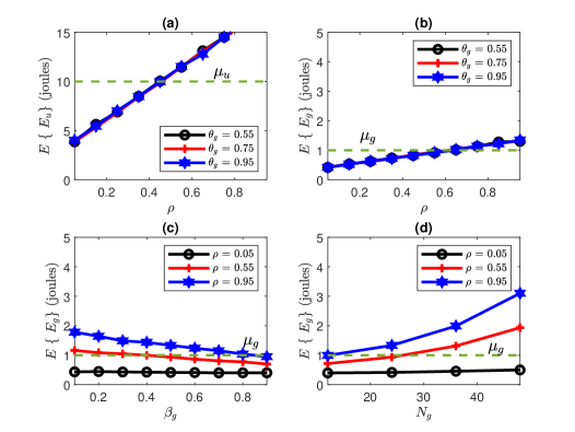
Fig. 2 presents the simulated average secrecy rates. Fig. 3 presents the simulated outage probabilities. Fig. 4 presents the simulated harvested energy. In Figs. 2 to 4, we have (a) average parameter for versus for different values (b) average parameter for versus for different values, and (c) average parameter for versus for different values, and and (d) average parameter for versus for different values, and . Note that changing changes since .
As shown in Fig. 2 (a) as increases or decreases, the SNR at increases and hence increases. However since considers ’s signal as noise, as increases, the noise variance increases and hence decreases as shown in Fig. 2 (b). Unlike as increases, the desired signal power at increases, which improves SNR and consequently . As shown in Fig. 2 (c) as increases, higher power factor is allocated for signal decoding rather than energy harvesting, which improves SNR as follows from the definition of and, hence, improves . does not have much impact on . Note that the upper bound (UB) in (17) is satisfied.

One key finding in Fig. 3 (a) is that very low values of , for example , i.e., when , might lead to . To achieve a desired , can be and . As can be inferred from Fig. 3 (b) to (d) to achieve a desired , can be , , , and .
As expected, the harvested energy at is much higher than that at the far User . To achieve a desired joules, should be as shown in Fig. 4 (a). Note that since the energy is harvested at before cancelling User ’s signal, changing does not have an impact on . As can be seen in Fig. 4 (b) to (d), to achieve joule, should be , should be and should be . has the most impact on the harvested energy at .

Following the exhaustive grid-based search operation, the optimal results under our simulation parameters are , , and . The reader can infer these values from and the explanatory plots in Figs. 2 to 4. The achieved maximized bits/sec/Hz and bits/sec/Hz while meeting the constraints on , , joules and joule.
V Conclusion
We presented an AN aided physical-layer security scheme for energy harvesting nodes operating under OFDM-based non-cooperative NOMA scheme. We showed that, with optimal choice of design parameters, it is possible to secure the considered system while transferring energy to multiple nodes under minimum outage probability constraints at legitimate users.
References
- [1] Y. Liu, Z. Ding, M. Elkashlan, and H. V. Poor, “Cooperative non-orthogonal multiple access with simultaneous wireless information and power transfer,” IEEE Journal on Selected Areas in Communications, vol. 34, no. 4, pp. 938–953, April 2016.
- [2] J. Tang, J. Luo, M. Liu, D. K. C. So, E. Alsusa, G. Chen, K. Wong, and J. A. Chambers, “Energy efficiency optimization for NOMA with SWIPT,” IEEE Journal of Selected Topics in Signal Processing, vol. 13, no. 3, pp. 452–466, June 2019.
- [3] A. Badawy, T. Khattab, T. ElFouly, C. Chiasserini, A. Mohamed, and D. Trinchero, “Channel secondary random process for robust secret key generation,” in 2015 International Wireless Communications and Mobile Computing Conference (IWCMC), 2015, pp. 114–119.
- [4] A. El Shafie, K. Tourki, and N. Al-Dhahir, “An artificial-noise-aided hybrid ts/ps scheme for OFDM-based SWIPT systems,” IEEE Communications Letters, vol. 21, no. 3, pp. 632–635, March 2017.
- [5] T. M. Hoang, A. El Shafie, D. B. Da Costa, T. Q. Duong, H. D. Tuan, and A. Marshall, “Security and energy harvesting for MIMO-OFDM networks,” IEEE Transactions on Communications, 2019. [Online]. Available: https://ieeexplore.ieee.org/document/8943160
- [6] Y. Liu, Z. Qin, M. Elkashlan, Y. Gao, and L. Hanzo, “Enhancing the physical layer security of non-orthogonal multiple access in large-scale networks,” IEEE Transactions on Wireless Communications, vol. 16, no. 3, pp. 1656–1672, 2017.
- [7] A. A. Nasir, X. Zhou, S. Durrani, and R. A. Kennedy, “Relaying protocols for wireless energy harvesting and information processing,” IEEE Transactions on Wireless Communications, vol. 12, no. 7, pp. 3622–3636, July 2013.
- [8] E. Tekin and A. Yener, “The general Gaussian multiple-access and two-way wiretap channels: Achievable rates and cooperative jamming,” IEEE Transactions on Information Theory, vol. 54, no. 6, pp. 2735–2751, June 2008.
- [9] Z. Ding, Z. Yang, P. Fan, and H. V. Poor, “On the performance of non-orthogonal multiple access in 5g systems with randomly deployed users,” IEEE Signal Processing Letters, vol. 21, no. 12, pp. 1501–1505, Dec 2014.
- [10] S. Boyd and L. Vandenberghe, Convex Optimization. Cambridge University Press, 2004.