Sagnac-type neutron displacement-noise-free interferometeric gravitational-wave detector
Abstract
The detection of low-frequency gravitational waves on Earth requires the reduction of displacement noise, which dominates the low-frequency band. One method to cancel test mass displacement noise is a neutron displacement-noise-free interferometer (DFI). This paper proposes a new neutron DFI configuration, a Sagnac-type neutron DFI, which uses a Sagnac interferometer in place of the Mach-Zehnder interferometer. We demonstrate that a sensitivity of the Sagnac-type neutron DFI is higher than that of a conventional neutron DFI with the same interferometer scale. This configuration is particularly significant for neutron DFIs with limited space for construction and limited flux from available neutron sources.
Keywords: Gravitational wave; Neutron interferometer; Displacement-noise free interferometer; Sagnac interferometer
1 Introduction
Since 2015, when LIGO first detected gravitational waves (GWs), numerous GW events have been observed [1, 2, 3]. The frequencies of GWs depend on their sources. For example, GWs in the low-frequency band around 1 Hz include important physical phenomena such as “primordial gravitational waves (PGWs)” [4]. However, the sensitivity of GW detectors in the low frequency band is limited by displacement noise. This noise arises from the fluctuating displacement of the detector’s test masses, due to thermal noise, noise from the suspension system, and seismic noise. One way to minimize this displacement noise is to send GW detectors up into space, as for LISA [5, 6] and DECIGO [7, 8]. Space-based GW detectors can reduce some displacement noise, such as suspension system noise, and ground vibration noise by floating the test mass in space. Cooling mirrors and suspension systems in space can also reduce thermal noise. However, space-based detectors require a significant amount of time, effort, and cost. The sensitivity in the low-frequency band also is limited by radiation pressure noise, which is one of the sources of displacement noise. Thus, reducing displacement noise is also essential.
Displacement-noise-free interferometery (DFI) is one of the methods for canceling all displacement noise [9]. In a coordinate system in the transverse-traceless gauge, GW signals and displacement noise can be distinguished [10, 11]. Therefore, multiple interferometer signals can be used to cancel displacement noise while preserving GW signals [12, 13]. This is the principle behind a DFI.
DFI is most sensitive in a limited frequency band that corresponds to the inverse of the time required for the beam to propagate between test masses. For example, a DFI with several kilometers of arm length is mostly sensitive near , which is much higher than the 1 Hz range where displacement noise is dominant. This is because of the high propagation speed of the laser light. Therefore, the neutron DFI was devised, in which a neutron beam is injected into the DFI. Neutrons have a finite mass, and their speed is much slower than that of photons. Therefore, even a DFI with several kilometers of arm length has good sensitivity around 1 Hz. Furthermore, the ability to select the speed of the incident neutrons is an advantage for optimizing the sensitivity of a DFI.
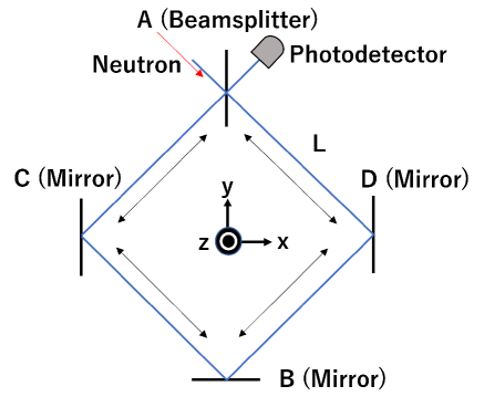
Various configurations of neutron DFI have already been developed [14, 15, 16]. In this paper, we present a neutron DFI configuration that uses a Sagnac-type interferometer. In the conventional configuration (single, two-velocity), shown in Figure 1, a single Mach-Zehnder interferometer is injected with neutrons of two velocities from two relative directions [15]. The solid arrows are the trajectories of neutrons incident through beamsplitter (BS) A, while the dashed arrows represent the trajectories of neutrons incident through BS B. After entering the Mach-Zehnder interferometer, the neutrons are divided into right and left paths by a beamsplitter (BS) and propagate along the two sides of the interferometer under the influence of GWs. The photodetector (PD) observes the interference state of the neutrons in the right and left paths. A Sagnac-type neutron DFI is injected with neutrons of four velocities from one direction. The PD observes the interference state of clockwise- and counterclockwise-propagating neutrons. This configuration allows a Sagnac-type neutron DFI to achieve higher sensitivity than a conventional neutron DFI of the same size interferometer and with the same number of neutrons.
In this paper, we discuss the Sagnac-type neutron DFI in terms of configuration and sensitivity. We discuss the configuration in Section 2, the method of canceling displacement noise in Section 3, the GW signals from neutron DFIs in Section 4, noise and sensitivity comparisons with the single, two-velocity neutron DFI in Section 5, and consider characteristics of the sensitivity curve in Section 6. Finally we present conclusions in Section 7.

2 Configuration of a Sagnac-type neutron DFI
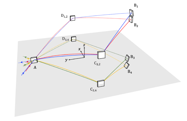
The configuration of a Sagnac-type interferometer is shown in Figure 2 from a bird’s-eye view (xy plane) and in Figure 3 from the side view (yz plane). Gravity acts in the z direction.The propagation of the neutron trajectory in the xy plane is a square with a side length of . BS A and mirrors B, C, and D are placed at the vertices of the square. Neutrons incident on A are divided into two directions and propagate in the interferometer in clockwise and counterclockwise orbits. Neutrons with four different velocities () are injected into the Sagnac-type neutron DFI. The horizontal and vertical velocities of neutrons with incident velocity () are denoted by and , respectively. As shown in Figure 3, hit mirrors and after a time from the incident, and at mirror after another . Mirror is angled in the xz plane so that it is perpendicular to the trajectory of in the yz plane. Then, only the x-component of the neutron velocity is preserved, and the neutron is reflected back. After reflection at mirror , both clockwise and counterclockwise orbits are symmetrical about the y-axis. Then, after the reflection at mirror the clockwise neutrons pass through BS A, and the counterclockwise neutrons are reflected at BS A. Their interference states are observed by the PD. In this paper, we set to be the time when the clockwise and counterclockwise neutrons are simultaneously reflected by mirror . Thus, neutrons are reflected by mirror and at , and hit BS A at . This means that neutrons with different velocities are reflected simultaneously only at mirror and hit mirrors and and BS A at different times.

2.1 Neutron trajectory
Let us consider the trajectory of taking into account the effect of falling due to gravity. Here, we ignore the mirror displacement temporarily and focus only on the neutrons trajectories. The coordinate at which the neutrons collide with A is denoted by
| (1) |
The velocity of the neutrons incident on A is denoted by
| (2) |
After a time interval elapses after the neutrons’ incidence on A, the neutrons collide with mirrors C and D. The velocities of the neutrons as they propagate from A to C and from A to D are given by
| (3) | ||||
| (4) |
The coordinates at where the neutrons impact mirrors C and D are
| (5) | ||||
| (6) |
The velocities of the neutrons as they propagate from C to B and from D to B and the coordinate where they impact mirror B are given by
| (7) | ||||
| (8) | ||||
| (9) |
After reflection at mirror B, oriented in the yz plane to be perpendicular to the trajectories of the neutrons, the clockwise-propagating neutrons propagate from B to C and from C to A. The counterclockwise-propagating neutrons propagate from B to D and from D to A. The velocities of the neutrons are given by
| (10) | ||||
| (11) | ||||
| (12) | ||||
| (13) |
Mirror is rotated about the x-axis to be perpendicular to the trajectory of neutrons projected on the yz plane. Thus, the z component of the velocity of the neutrons reverses its sign after reflection by mirror . Neutrons propagate through this trajectory. The velocities of clockwise- and counterclockwise-propagating neutrons can be defined as
| (14) |
| (15) |
2.2 Neutron pathway for DFI realization
The realization DFI necessitates combining pairs of neutron signals that contain the displacement noise from the same test mass. This is because displacement noise from different points, even on the same test mass, are not correlated. To cancel the displacement noise at a point on C(D), two neutron signals that hit the same point on C(D) are required. Similarly, to cancel the displacement noise at a point on A, we need two signals that reflect at the same point on A, with the displacement noise at a point on C(D) already canceled.
To summarize, and and and must impact the same point on C(D), and all four neutrons must impact the same point on A. We determine and for each neutron group, , to satisfy these conditions using the following procedure:
1. Set four horizontal incident neutron velocities ().
2. Set as the slowest horizontal velocity and as the fastest horizontal velocity.
3. Determine such that and are within the range of neutron velocities that can be injected. In this paper, we set the slowest neutron velocity as 75 m/s and the fastest neutron velocity as 100 m/s. (This is the range of neutron velocities for which comparable fluxes can be expected.)
4. Calculate , the height at which impact mirror () as
| (16) |
and determine and to satisfy and . Note that the height at which all neutrons impact mirror A is . Figure 4 shows the neutron pathways that satisfy the conditions for the neutron velocities.
3 Method of canceling displacement noise
3.1 Displacement noise in the time domain
First, let us consider only the displacement noise experienced by neutrons, . When considering the displacement noise that the neutrons receive from mirrors , , and , we omit the subscripts for the mirrors B, C, and D. We set as the displacement of test mass (A, B, C, D) in the direction normal to its surface. The magnitude of the phase change of the neutrons, caused by is expressed in terms of the wavenumber of the neutrons, as
| (17) |
Here, is the mass of the neutrons, and is Dirac’s constant. Table 1 shows the displacement noise that the clockwise and counterclockwise-propagating neutrons experience. Note that corresponds to the time when the neutrons are simultaneously reflected by mirror B. Also, since clockwise-propagating neutrons traverse BS A twice, they do not receive displacement noise from BS A.
| Test mass | A | C | B | D | A |
|---|---|---|---|---|---|
| clockwise | 0 | 0 | |||
| counterclockwise |
The total phase change of clockwise- and counterclockwise-propagating is given by
| (18) |
| (19) |
The phase change of the interfered neutrons at the PD is given by
| (20) | ||||
The clockwise- and counterclockwise-propagating neutrons impact the same point on mirror B simultaneously, thus they receive identical displacement noise from the motion of B. As a result, the signal after they interfere contains no displacement noise from B. However, due to the fact that the clockwise- and counterclockwise-propagating neutrons interact with A, C, and D at different times, displacement noise cannot be fully eliminated.
3.2 Displacement noise in frequency domain
In order to cancel the displacement noise of A, C, and D, we must consider the displacement noise in the frequency domain. In this paper, we define the Fourier transform as follows
| (21) |
Note that lowercase letters represent variables in the time domain and uppercase letters represent variables in the frequency domain. We can express as
| (22) |
where is the complex amplitude of the mirror displacement at frequency . We can express in the frequency domain as
| (23) |
Since the normals of the surfaces of test masses A, C, and D have only x-components, Equation 17 can be rewritten using the unit vector in the x direction as
| (24) |
where is the x component of . Although the z component of changes with time due to gravity, it does not affect , which is proportional to the inner product of and . We treat as a time-invariant variable because the calculation of (in Equation 23) does not require consideration of the time variation of . Considering the velocity of the neutrons at the time they impact each test mass, the component of Equation 20 is given by
| (25) | ||||
3.2.1 Method of cancelling displacement noise of mirrors C and D
First, we consider the displacement noise of mirrors C and D in the frequency domain. Table 2 shows the displacement noise of C and D in the interferometer signals of the neutrons.
| Test masses | C | D |
|---|---|---|
| clockwise | ||
| counterclockwise | ||
| Interferometer Signal |
contains the displacement noise of mirrors C and D. In order to normalize the interferometer signals with different neutron velocities, we divide by and we obtain
| (26) |
Here, we take into account and . Since the ratio of the magnitudes of the displacement noise caused by C and D in and is , they can be eliminated by the following signal processing:
| (27) | |||
| (28) |
We can explain the fact that has no displacement noise from C and D with a phasor diagram as shown in Figure 5. The green and yellow lines represent the displacement noise in and , respectively. Since the green and yellow lines (both solid and dashed arrows, which represent the displacement noise due to mirrors and , respectively) are parallel in the phasor diagram, they can be simultaneously eliminated by subtracting a real coefficient. The details of the calculations are as follows:
| (29) | ||||
Similarly, we can obtain , that has no displacement noise from C and D as
| (30) | ||||
| (31) |

3.2.2 Method of canceling displacement noise of A
In this subsection, we will focus on the displacement noise of BS A in the frequency domain. In the Sagnac-type neutron DFI configuration, the clockwise-propagating neutrons always pass through A and are thus not affected by its displacement. However, the counterclockwise neutrons accumulate the displacement noise of A twice, at and . If A is displaced by at , the counterclockwise neutron propagation distance increases, leading to an advance in the neutron phase. Conversely, if A is displaced by at , the counterclockwise neutron propagation distance decreases, resulting in a delay in the neutron phase. As a result, the sign of the displacement noise of A is opposite for and . The impact of the displacement noise of A on can be expressed as
| (32) |
Similar to the method for canceling the displacement noise of mirrors C and D in Equation 27, the displacement noise of A can be cancelled by combining two signals containing the displacement noise of A. If we cancel the displacement noise of A using and , which contain noise components from A only, we can obtain a signal that has all displacement noise of the Sagnac-type DFI canceled:
| (33) |
where
| (34) |
Specifically, the coefficient of in () and that in () are multiplied by and , respectively, and subtracted to cancel the BS A displacement noise.
3.2.3 Sagnac effect in Sagnac-type neutron DFI
In the Sagnac-type neutron DFI, neutrons undergo the Sagnac effect and experience a phase change when they are detected after circling the interferometer, if the interferometer rotates with a certain angular frequency . From the perspective of the inertial system, the rotation of the interferometer can be expressed by the displacement of each test mass. However, in the DFI, all displacement noise is canceled. Thus, the signals obtained from a Sagnac-type neutron DFI, , do not include the Sagnac effect.
4 Gravitational wave signal of neutron DFI
4.1 Gravitational wave signal in a Sagnac-type neutron DFI
Let us consider the Klein-Gordon equation for a particle with mass ,
| (35) |
The wave function at time and position with wavenumber vector and angular frequency of neutrons is
| (36) |
Due to the effect of GWs, Equation 36 becomes
| (37) |
In the TT gauge, if the GWs propagate through flat spacetime, we can write
| (38) |
Here, is a metric of a flat space. In this coordinate system, from Equation 35 we obtain
| (39) |
The leading order term in is
| (40) | ||||
| (41) |
Here, assuming that the wavenumber vector is sufficiently small, we can make the following approximation,
| (42) |
As mentioned in Section 2, propagate through the interferometer on the trajectories represented by Equations 1-13. Here we reset the time, that is, we set the time to be when the cross the surface of of BS A. The wavenumber vectors of the neutrons during propagation are given by
| (43) | ||||
| (44) | ||||
| (45) | ||||
| (46) | ||||
| (47) | ||||
| (48) | ||||
| (49) | ||||
| (50) |
The phase change of caused by GWs is given by
| (51) |
Therefore, the phase change induced by the GWs during propagation between points red D and B is
| (52) |
Defining as the Fourier transform of the GWs at angular frequency ,
| (53) |
If we expand at the position , we obtain the second term of order . ( is a GW wave vector.) However, this second term is negligible because the typical size of a Sagnac-type DFI is , and is much smaller for GWs at 1Hz [14]. For simplicity, we ignore the -dependence of . In this paper, we calculate the response of a Sagnac-type neutron DFI to cross-mode GWs traveling in the z-axis direction. The Fourier transform of the GW signal received by a neutron with velocity is:
| (54) |
where
| (55) |
When GWs of amplitude , polarization angle , and angle of incidence arrive, the corresponding rotation matrix is
| (56) |
and the GW strain is
| (57) |
Similarly, the GW signals received by the clockwise- and counterclockwise-propagating neutrons are given by
| (60) | |||
| (61) |
For the DFI scheme, detection timing is crucial. In practice, the timing of neutron detection is affected by clock noise . Clock noise in terms of neutrons’ phase is the cumulative effect of clock deviations at each mirror or BS due to reflections. We define the phase clock noise and and their Fourier transforms and as
| (62) | |||
| (63) |
The phase of the are given by
| (64) | |||
| (65) |
The GW signal that the receive during propagation between A and C is given by
| (66) | ||||
where is the GW amplitude. Because of the difference in neutron propagation direction, GW signals that neutrons receive during propagation along each side of the Sagnac-type neutron DFI are expressed as
| (68) |
The sign of the GW signal from the z direction received by the neutrons depends on the velocity of the neutrons in the xy-plane. The sign of the GW signal received by neutrons traveling along the same path in the opposite direction is opposite. Thus, .
By combining signals for displacement noise cancellation in and , the GW signal contained in is calculated as
| (69) |
Thus,
| (70) |
and
| (71) | ||||
4.2 Gravitational wave signal of a single, two-velocity neutron DFI
Similar to the GW signals in the Sagnac-type neutron DFI, the GW signals in the single, two-velocity neutron DFI , are obtained as follows:
| (72) |
where
| (73) |
5 Sensitivity
DFI signal, as its name implies, is free from displacement noise. Therefore, the sensitivity of a DFI to GW signals is limited by neutron shot noise. If the flux of the neutrons is , then their shot noise is given by
| (74) |
In a neutron DFI, a signal without any displacement noise is obtained by combining signals from neutrons with four velocities. Since , and are all independent of each other, the shot noise after DFI combination is given by
| (75) |
Similarly, the shot noise of a single, two-velocity neutron DFI is given by [15]
| (76) |
Note that the factor of 2 in and comes from the fact that a single, two-velocity neutron DFI uses two neutron beams with velocities and . In the GW detection, the GW signal is expressed in the unit of as,
| (77) |
Setting = 1, we obtain the amplitude spectral density of shot noise limited sensitivity to GW amplitude of the Sagnac-type neutron DFI in .
| (78) |
where is the GW signal normalized by the GW amplitude ,
| (79) |
In this paper, we optimize the sensitivity by varying the velocity of neutrons incident on the DFI. We have calculated the sensitivity for various combinations of neutron velocities in the range of to , where similar fluxes are expected. Note that the neutron velocities were varied at intervals, and we assume a constant neutron flux at all velocities (). Table 3 shows the most sensitive combinations of neutron velocities.
| i | |||
|---|---|---|---|
| 1 | 93.31 | 87.00 | 33.74 |
| 2 | 75.00 | 69.00 | 29.39 |
| 3 | 77.04 | 77.00 | 2.59 |
| 4 | 100.00 | 100.00 | 0 |
Let us compare the sensitivity of a Sagnac-type neutron DFI and a single, two-velocity neutron DFI with the same interferometer size ( = ), four-velocity neutron sources, and the same neutron flux. These sensitivities are optimized for the incident neutron velocities. The sensitivity of the single, two-velocity neutron DFI is calculated with and .

Figure 6 shows that the sensitivity of the Sagnac-type neutron DFI is higher than that of the single, two-velocity neutron DFI around . This is indicated by the dip in the Sagnac-type curve being lower than that of the single, two-velocity curve at that frequency. The signal-to-noise ratio (SNR) is defined as
| (80) |
where , . The ratio of SNR of the Sagnac-type neutron DFI to the single, two-velocity DFI, , for GW signals from binary stars proportional to [8, 17] with arbitrary magnitude is
| (81) |
6 Discussion
First, let us consider the amount of phase change experienced by as they propagate inside the interferometer due to GWs traveling in the z direction. Newtrons, traverse one side of the interferometer in time, . When cross-mode GWs with a period of pass the interferometer, the neutrons undergo the maximum phase shift. In the Sagnac-type neutron DFI, the neutrons are affected by GWs as they propagate through four sides of the interferometer. In a single, two-velocity neutron DFI the neutrons are affected by GWs only as they propagate through two sides of the interferometer. The neutrons in the Sagnac-type neutron DFI experience twice the phase change, , compared to those in a single two-velocity neutron DFI.
Thus, the ratio of to in the Sagnac-type neutron DFI is twice that in a single two-velocity neutron DFI.
Figure 6 shows the best sensitivity, , of the Sagnac-type neutron DFI is , and that of the single two-velocity neutron DFI is . These magnitudes differ only by a factor of about 1.5, due to a difference in signal processing.
The frequency (period) of the GWs that produce the largest phase change depends on the of the neutrons used to calculate the DFI signal. Since several neutrons, , (i = 1 to 4) are used,
the DFI signal is calculated by subtracting the neutron signals with different velocities from each other, and a part of the GW signals is also subtracted.
The Sagnac-type neutron DFI with more subtractions of neutron signals loses more GW signals in the signal processing than a single, two-velocity neutron DFI. Thus, the best sensitivity of the Sagnac-type neutron DFI and that of the single, two-velocity neutron DFI differ only by a factor of about 1.6.
Next, let us consider the peaks that appear in the Sagnac-type neutron DFI sensitivity curve.
These peaks have two origins. The first is that neutrons traverse square orbits, and the second is the coefficients and used in signal processing.
According to Equation 68, when .
This means that the sums of the GW signals with periods of or () on the is zero. First, when propagate along one side of the interferometer, cross-mode GWs with a period of induce a positive (or negative) phase change and an equal and opposite phase change. Second, the are not sensitive to GWs with a period of . Neutrons with reflected from the mirrors bend their propagation direction by 90 degrees every .
Cross-mode GWs with a period of give a constant phase change while the neutrons propagate along one side of the interferometer, and an equal and opposite phase change while they propagate along the opposite. Therefore, the round trip phase change induced by the cross-mode GWs with a periods of is zero. Since the neutron signals do not have a GW signal with a specific period (frequency), the DFI is not sensitive to GWs at that frequency.
Next, let us focus on the coefficients used for signal processing and . When , . When or , . To summarize, when
| (82) |
Similarly, when
| (83) |
Thus, when
| (84) |
The lowest frequencies that satisfy each of these conditions derived from and are respectively,
| (85) |
Similarly, when
| (86) |
The lowest frequencies that satisfy each of these conditions derived from and are respectively,
| (88) |
in addition, at the frequencies corresponding to ( and ) and ( and ), respectively,
7 Conclusion
In this paper, we propose a Sagnac-type neutron DFI and have confirmed analytically that DFI can be realized by injecting neutrons into a Sagnac-type neutron interferometer considering the influence of gravity. We have also shown that the sensitivity of the Sagnac-type neutron DFI is superior to that of the conventional single, two-velocity DFI. When canceling displacement noise with multiple signals, the location and time at which the neutrons receive the displacement noise are important. In order to cancel the displacement noise of all test masses with four neutron signals, we adjust the neutrons’ velocities and injection angles to satisfy the following conditions: 1) The neutron trajectories are symmetrical about the y-axis. 2) The four neutron groups are incident on the interferometer at the same point on BS A. 3) Neutrons, and ( and ) hit the same points on and ( and ) in Figure 4, respectively. Additionally, we optimize the incident neutron velocities to achieve the best sensitivity for both the Sagnac-type neutron DFI and the single, two-velocity neutron DFI.
One of the technical challenges we face in realizing a Sagnac-type neutron DFI is the neutron reflection angle. Currently, mirrors with a reflection angle of only a few degrees have been created using current technology. However, there is no fundamental principle that limits the reflection angle. Thus, it is possible to develop a mirror with a large reflection angle, such as 45 degrees. Other practical issue that must be considered when demonstrating neutron DFI experimentally is the accuracy and capability of the instrument. The sensitivity of neutron DFI is affected by factors such as the accuracy of the distance between test masses, the reflectivity of the mirrors, the flux of neutrons and the accuracy of the displacement noise cancellation. For example, neutron beams with velocity ranging from 75 m/s to 100 m/s are limited to a flux of about /s using the PF2 beamline at the ILL reactor in France. In the future, fluxes of up to /s can be anticipated using beams from the ESS accelerator neutron source, which is currently under construction. We anticipate that even higher fluxes will be possible in principle, although we will have to wait for future facilities to be built. The accuracy of noise cancellation depends on the precision of neutron velocity determination (this is frequency noise). Increasing the distance from the neutron source to the interferometer increases the required accuracy of velocity determination. If the velocity is determined with an accuracy of 0.1 % or better, the sensitivity curve will not be affected as long as the mirror displacement is below . For these reasons, developing such a technique is challenging, but we believe it is feasible. A more detailed study of these technical issues will be the subject of future work.
Acknowledgments
We would like to thank R. L. Savage for English editing. This work was supported by the Japan Society for the Promotion of Science (JSPS) KAKENHI Grant Number JP19K21875. A. N. is supported by JSPS KAKENHI Grant Nos. JP23K03408, JP23H00110, and JP23H04893.
References
- [1] J. Aasi, et al. L.I.G.O Advanced, LIGO Scientific Collaboration, Class. Quantum Gravity 32 (2015) 074001.
- [2] F. Acernese, et al., Advanced Virgo: a second-generation interferometric gravitational wave detector, Class. Quantum Gravity 32 (2014) 024001.
- [3] B.P. Abbott, et al., LIGO Scientific Collaboration and Virgo Collaboration, Observation of gravitational waves from a binary black hole merger, Phys. Rev. Lett. 116 (2016) 061102.
- [4] S. Kuroyanagi, Implications of the B-mode Polarization Measurement for Direct Detection of Inflationary Gravitational Waves, Phys. Rev. D 90, 063513 (2014)
- [5] K. Danzmann, et al., LISA and its pathfinder, Nat. Phys. 11 (2015) 613.
- [6] J. Crowder, N.J. Cornish, Beyond LISA: exploring future gravitational wave missions, Phys. Rev. D 72 (2005) 083005.
- [7] N. Seto, S. Kawamura, T. Nakamura, Possibility of direct measurement of the acceleration of the Universe using 0.1 Hz band laser interferometer gravitational wave antenna in space, Phys. Rev. Lett. 87 (2001) 221103.
- [8] S. Kawamura, et al., Space gravitational-wave antennas DECIGO and B-DECIGO, Int. J. Mod. Phys. D 28 (2019) 1845001.
- [9] Y. Chen, et al., Interferometers for displacement-noise-free gravitational-wave detection, Phys. Rev. Lett. 97 (2006) 151103.
- [10] S. Kawamura, Y. Chen, Displacement-noise-free gravitational-wave detection, Phys. Rev. Lett. 93 (2004) 211103.
- [11] Y. Chen, S. Kawamura, Displacement-and timing-noise-free gravitational-wave detection, Phys. Rev. Lett. 96 (2006) 231102.
- [12] S. Sato, et al., Demonstration of displacement- and frequency-noise-free laser interferometry using bidirectional Mach-Zehnder interferometers, Phys. Rev. Lett. 98 (2007) 141101.
- [13] K. Kokeyama, et al., Development of a displacement- and frequency-noise-free interferometer in a 3D configuration for gravitational wave detection, Phys. Rev. Lett. 103 (2009) 171101.
- [14] A. Nishizawa, et al., Neutron displacement noise-free interferometer for gravitational-wave detection, Phys. Rev. D 105 (2022) 124017.
- [15] S. Iwaguchi, et al., Displacement-noise-free neutron interferometer for gravita-tional wave detection using a single Mach-Zehnder configuration, Phys. Lett. A 441 (2022) 128150.
- [16] S. Iwaguchi, et al., Displacement-noise-free interferometeric gravitational-wave detector using unidirectional neutrons with four speeds, Phys. Lett. A 458 (2023) 128581.
- [17] M. Shibata, et al., Merger of binary neutron stars with realistic equations of state in full general relativity, Phys. Rev. D 71 (2015) 084021.