Reconfigurable Intelligent Surfaces Empowered Cooperative Rate Splitting with User Relaying
Abstract
Cooperative rate splitting (CRS), built upon rate splitting multiple access (RSMA) and opportunistic user relaying, has been recognized as a promising transmission strategy to enhance the user fairness and spectral efficiency in multi-antenna broadcast channels. To further boost its performance, the interplay of CRS and reconfigurable intelligent surface (RIS) is investigated in this work. Specifically, a novel RIS-aided CRS transmission framework is proposed and the corresponding resource allocation problem to maximize the minimum rate among users is investigated. An alternative optimization algorithm is then proposed to optimize the transmit beamforming, common rate allocation, and RIS phases, iteratively. Numerical results show that the proposed RIS-aided CRS transmission framework significantly improves the spectral efficiency compared with its non-cooperative counterpart and other schemes without RIS.
Index Terms:
Cooperative rate splitting (CRS), reconfigurable intelligent surface (RIS), rate splitting multiple access (RSMA), max-min fairnessI Introduction
Among numerous potential techniques for the sixth generation (6G) communication networks, rate-splitting multiple access (RSMA), as a novel non-orthogonal transmission framework and interference management strategy in the physical (PHY) layer, has shown its great potential for improving the spectral efficiency, energy efficiency, user fairness, robustness to the channel state information uncertainty, etc [1]. The principle of (1-layer) RSMA is to split user messages into common and private parts, encode the common parts into a common stream using a codebook shared by all users while encoding the private parts independently for the corresponding users only. By superposing the common stream on top of the private streams at the transmitter and decoding the common stream and the intended private stream sequentially at the receivers, RSMA achieves a more versatile interference management of partially decoding the interference and partially treating the interference as noise [2]. Such 1-layer RSMA only requires one layer of successive interference cancellation (SIC) at each receiver, and is a more generalized transmission scheme than orthogonal multiple access (OMA) and linearly-precoded space division multiple access (SDMA) [3, 4]. One major characteristic of 1-layer RSMA is that the common stream is required to be decoded by all users and therefore the achievable common rate111The rate of the common stream is simply denoted as “common rate”. is limited by the worst-case rate of decoding the common stream at all users. To enhance the common rate, a two-user cooperative rate splitting (CRS) is proposed in [5], and further extended to the -user case in [6]. By enabling one user to opportunistically forward its decoded common message to the user with the worst-case common rate, CRS enlarges the rate region [5], enhances user fairness [6], improves the coverage [1], and maximizes the secrecy rate [7] compared with cooperative non-orthogonal multiple access (NOMA) and non-cooperative 1-layer RSMA, SDMA, NOMA.
Another enabling technique for 6G that has gained significant attention is reconfigurable intelligent surface (RIS) [8]. As a meta-surface containing a large number of discrete and passive elements, RIS is capable of controlling wireless channels by dynamically reconfiguring the reflection coefficients. Therefore, the spectral and energy efficiencies can be further improved. Inspired by the appealing performance benefits of RIS and RSMA, existing works have investigated the interplay between RIS and RSMA in terms of the outage probability [9, 10], max-min fairness [11], and spectral efficiency [12, 13]. However, all the above works only consider RIS-aided non-cooperative RSMA. So far, the interplay of CRS and RIS has not been investigated yet.
In this paper, we propose a novel RIS-aided CRS transmission framework, which enables an RIS to assist the direct transmission from the base station (BS) to the users and the opportunistic transmission of the common stream between users. We formulate a max-min fairness optimization problem to jointly optimize RIS phases, transmit beamforming, common rate allocation, and the time slot allocation between the direct and opportunistic transmissions under the transmit power constraint and the unit-modulus constraints of the RIS phases. To solve the problem, an alternative optimization (AO) algorithm is proposed to iteratively optimize the transmit beamforming and the RIS phases. Numerical results show that the proposed RIS-aided CRS transmission framework improves the worst-case achievable rate among users compared with its non-cooperative counterpart and other schemes without RIS. Therefore, we conclude that the proposed RIS-aided CRS scheme enhances user fairness and is more powerful than the existing transmission schemes.
II System Model and Problem Formulation
II-A System Model
Consider a multi-user multiple-input single-output (MISO) transmission network, where a BS equipped with transmit antennas simultaneously serves two single-antenna users indexed by and . Without loss of generality, is assumed to have a better channel to the BS than , and it opportunistically acts as a half-duplex (HD) relay to forward the signal to . There is one RIS with passive reflecting elements to assist the transmission from BS to the two users and from to . The RIS elements are indexed by . The channels between BS and RIS, BS and , RIS and , and are denoted by , and , respectively. The system model is delineated in Fig. 1.
Two phases are involved in the proposed model, namely, the direct transmission phase and the cooperative transmission phase. In the direct transmission phase, also known as (a.k.a.) the first time slot, the BS transmits signals to two users based on the principle of 1-layer RSMA. In the meanwhile, the transmit signal is reflected by the RIS to the two users. In the cooperative transmission phase, a.k.a. the second time slot, the BS is silent and transmits the common stream of 1-layer RS to and the signal is reflected by the RIS to . We assume as the fraction of time allocated to the first phase. The rest is allocated to the second phase.
II-A1 Direct Transmission Phase
Following the principle of 1-layer RSMA [14], the message intended to user- is split into a common part and a private part . and are combined and encoded into common stream using a common codebook shared by the two users. The private parts and are independently encoded into private streams and , respectively. Assume each stream has zero mean and unit variance, i.e., . Let and respectively denote the stream vector and the beamforming matrix, where . The resulting transmit signal at the BS in the first time slot is expressed as
| (1) |
The transmit power constraint is given by , where is the maximum transmit power of the BS. The received signal at user- in the first time slot is given as
| (2) |
where is the phase matrix in the first time slot. is the additive white Gaussian noise (AWGN) which follows .

Once user- receives in the first time slot, it first decodes the common stream by fully treating all private streams as interference. The achievable rate of decoding the common stream at user- in the first time slot is
| (3) |
After removing the decoded common stream, the rate of decoding the private stream is
| (4) |
where and .
II-A2 Cooperative Transmission Phase
In the cooperative transmission phase, the BS is silent and forwards the decoded common stream to by employing the non-regenerative decode-and-forward (NDF) protocol [5] with the transmit power , a phase matrix and a codebook generated independently at the BS. The received signal at with the aid of RIS is given as
| (5) |
where and are channels between and RIS, and RIS, respectively. The rate of decoding the common stream at in the second time slot is
| (6) |
combines the decoded common stream from two time slots. To make sure the common stream can be successfully decoded by both users, the achievable rate of decoding the common stream at and is obtained as follows
| (7) |
is shared by both users for the transmission of and . Accordingly, it satisfies
| (8) |
where and are parts of allocated to transmit the common parts of the two users. Let . The total achievable rate of user is .
II-B Problem Formulation
The goal of this work is to maximize the user fairness. In particular, we jointly design the transmit beamforming , rate allocation , RIS phases and time slot allocation with the aim of maximizing the minimum rate (max-min rate) of the users while satisfying the transmit power constraint. The max-min rate problem for the proposed RIS-aided CRS is formulated as
| (9a) | ||||
| s.t. | (9b) | |||
| (9c) | ||||
| (9d) | ||||
| (9e) | ||||
| (9f) | ||||
where constraint (9b) ensures that each user successfully decodes the common stream. Constraint (9e) is the range of the phase for each RIS element, and (9f) presents the transmit power constraint at the BS. Problem is highly intractable and non-convex. To solve the problem, we develop an AO-based optimization algorithm in the next section to alternatively optimize the RIS phases and the remaining variables .
III Proposed Optimization Framework
In this section, we specify the proposed AO framework to solve problem . The problem is first decomposed into two subproblems, one for joint transmit beamforming, common rate and time slot optimization, and the other one for the RIS phase matrix optimization. Both subproblems are respectively solved by success convex approximation (SCA)-based algorithms in an iterative manner until convergence.
III-A Joint Beamforming, Common Rate, and Time Slot Optimization
With given , the channels from BS to IRS and IRS to users are fixed. For notational simplicity, we denote the effective channel in the first time slot as . By introducing an auxiliary variable to denote the minimum rate of the two users, problem is equivalently transformed to
| (10a) | ||||
| s.t. | (10b) | |||
is still non-convex due to the rate expressions and in (10b) and (9b). To solve , we introduce slack variable vectors , , and , where and denote the private and common stream rate vectors, respectively, and denote the signal-to-interference-plus-noise ratio (SINR) vectors for private and common streams, respectively. With the slack variables introduced above, is equivalently transformed into
| (11a) | ||||
| s.t. | (11b) | |||
| (11c) | ||||
| (11d) | ||||
| (11e) | ||||
| (11f) | ||||
| (11g) | ||||
| (11h) | ||||
To handle the nonconvexity of constraints (11b)–(11d), (11g) and (11h), we next apply the SCA method. Constraint (11b) contains a bilinear function , which can be rewritten as . Therefore, can be approximated by the first-order Taylor approximation at the point , which is given as
| (12) | ||||
With (12), (11b)–(11d) are approximated at iteration around the point as
| (13) | ||||
By further transforming (11g) and (11h) into the following difference-of-convex (DC) forms and using the first-order Taylor approximations to reconstruct the concave parts of the DC constraints, constraints (11g) and (11h) at iteration are approximated respectively at the point by
| (14) | ||||
With the above approximations, problem at iteration can be approximated by the following convex problem
| (15) | ||||
| s.t. |
Problem (15) is a convex problem, which can be solved using the SCA method. The detailed process of the SCA method to solve is illustrated in Algorithm 1.
III-B RIS Phase Optimization
Given transmit beamforming vector , rate allocation , and time slot allocation , we also introduce an auxiliary variable and reformulate problem as
| (16a) | ||||
| s.t. | ||||
As the channel between and is known, the RIS phase in the cooperative transmission time slot can be designed as [15]. Hence, we only need to optimize the RIS phase matrix . We denote , , and . With the assistance of , we obtain , where . To ease notations, we denote . We further introduce slack variables , , , and . and denote the SINR and rate vectors of private streams, respectively. and denote the SINR and rate of the common stream of in the first time slot. Then, problem is reformulated as
| (17a) | ||||
| s.t. | (17b) | |||
| (17c) | ||||
| (17d) | ||||
| (17e) | ||||
| (17f) | ||||
| (17g) | ||||
| (17h) | ||||
| (17i) | ||||
To handle the non-convexity of constraint (17f), we adopt the penalty method to transform into
| (18a) | ||||
| s.t. | (18b) | |||
| (18c) | ||||
where is a large positive constant. The objective function can be approximated around the point at iteration by the first-order Taylor approximation of , which is given by
| (19) |
To handle the nonconvexity of constraints (17g) and (17h), we introduce variables and , and constraints (17g) and (17h) are equivalent to
| (20) | ||||
and
| (21) | ||||
(20) and (21) are still non-convex, we therefore adopt the first-order Taylor approximation at point . (20) and (21) become
| (22) | ||||
Similarly, constraint (17i) can be approximated by
| (23) | ||||
Based on the above approximation methods, problem is approximated by the following convex problem at iteration .
| (24a) | ||||
| s.t. | ||||
The detailed SCA method to solve is illustrated in Algorithm 2.
III-C Alternative Optimization
The proposed AO algorithm to jointly optimize the RIS phases, transmit beamforming, common rate and time slot allocation is shown in Algorithm 3. Starting from a feasible beamforming matrix , time slot allocation , rate allocation , a RIS phase matrix , in -th iteration, we first update with a fixed by Algorithm 1. For a given , the RIS phase matrix is then updated based on the SCA method with as the initialization point. The max-min rate is then calculated based on the updated and . The process is repeated until convergence.
Convergence Analysis: For the precoder optimization problem , the proposed SCA algorithm ensures the monotonic increase of the objective function. This is due to the fact that the solution of problem (15) at iteration is a feasible point of problem (15) at iteration . Due to the transmit power constraint (9f), the solution sequence is bounded above, which implies that the convergence of Algorithm 1 is guaranteed. Similarly, for the RIS phase problem , the solution of problem (24) at iteration is also a feasible point for the problem (24) at iteration . Due to the modulus constraint (9e), the solution sequence is bounded above, which guarantees the convergence of Algorithm 2. The monotonic increase of the objective functions for and implies that the solution of at iteration is also a feasible point for at iteration . Hence, the convergence of AO algorithm is guaranteed.
IV Numerical Results
In this section, we evaluate the performance of the proposed system model. The following schemes are compared:
-
•
RIS CRS—This is the scheme proposed in Section II.
-
•
RIS RSMA—This is a special case of “RIS CRS” when is fixed to 1.
-
•
RIS SDMA—This is a special case of “RIS CRS” when the power allocated to the common stream is zero.
- •
- •
-
•
no RIS SDMA—This is the multi-user linearly precoded SDMA without using RIS, as studied in [3].
The max-min rate problems of RIS CRS, RIS RSMA and RIS SDMA are solved by Algorithm 3 while the corresponding problems of no RIS CRS, no RIS RSMA and no RIS SDMA are solved by SCA directly.

The simulation setting is shown in Fig. 2. The BS and RIS are located at and , respectively. and are located at and . For simplicity, the small-scale fading of all channels are modeled as Rayleigh fading. The path loss of the channels are modeled by , where dB is the path loss at the reference distance m, denotes the link distance and refers to the path loss exponent. In particular, the path loss exponents of BS to , BS to , BS to RIS, RIS to all users and to are set to be and . Without loss of generality, we assume the transmit power at the BS and the relaying user are equal. The noise tolerance is dBm and the convergence tolerance is .
Fig. 3 shows the max-min rate of different strategies versus the transmit power when . It shows that the proposed RIS-aided CRS scheme outperforms all other schemes. The relative max-min rate gain of RIS CRS over RIS RSMA and no RIS CRS are at least 6.6 and 19.5 when SNR is 15 dB. By using the RIS-aided CRS model, the max-min rate of the system increases significantly.
Fig. 4 shows the max-min rate of different strategies versus the number of passive reflecting elements at the RIS when the number of transmit antenna is and SNR is 15 dB. The three schemes all achieve significant max-min rate improvement as the number of RIS element increases. The proposed RIS-aided CRS scheme achieves a higher max-min rate than RIS-aided RSMA and RIS-aided SDMA. But the rate gain of RIS-aided CRS over RIS-aided RSMA decreases as the number of RIS elements increases.
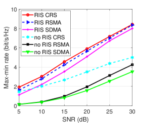
Fig. 5 illustrates the convergence of the proposed AO algorithm when and SNR is 15 dB. In general, the algorithm can converge with 50 iterations.
V Conclusion
In this work, we propose an RIS-aided CRS downlink transmission network. The transmit beamforming vector, the RIS phase matrix, the common rate and time slot allocation are jointly optimized to maximize the minimum rate among users. To solve this problem, we propose an AO algorithm that alternatively optimizes the phase matrix and the remaining variables. Numerical results show the proposed scheme which combines CRS and RIS enhances the spectral efficiency and user fairness.


References
- [1] Y. Mao, O. Dizdar, B. Clerckx, R. Schober, P. Popovski, and H. V. Poor, “Rate-splitting multiple access: Fundamentals, survey, and future research trends,” IEEE Commun. Surveys Tuts., 2022.
- [2] B. Clerckx, H. Joudeh, C. Hao, M. Dai, and B. Rassouli, “Rate splitting for MIMO wireless networks: A promising PHY-layer strategy for LTE evolution,” IEEE Commun. Mag., vol. 54, no. 5, pp. 98–105, May. 2016.
- [3] Y. Mao, B. Clerckx, and V. O. K. Li, “Rate-splitting multiple access for downlink communication systems: bridging, generalizing, and outperforming SDMA and NOMA,” EURASIP J. Wireless Commun. Netw., vol. 2018, no. 1, p. 133, May. 2018.
- [4] B. Clerckx, Y. Mao, R. Schober, and H. V. Poor, “Rate-splitting unifying SDMA, OMA, NOMA, and multicasting in MISO broadcast channel: A simple two-user rate analysis,” IEEE Wireless Commun. Lett., vol. 9, no. 3, pp. 349–353, Mar. 2020.
- [5] J. Zhang, B. Clerckx, J. Ge, and Y. Mao, “Cooperative rate splitting for MISO broadcast channel with user relaying, and performance benefits over cooperative NOMA,” IEEE Signal Process. Lett., vol. 26, no. 11, pp. 1678–1682, Nov. 2019.
- [6] Y. Mao, B. Clerckx, J. Zhang, V. O. K. Li, and M. A. Arafh, “Max-min fairness of k-user cooperative rate-splitting in MISO broadcast channel with user relaying,” IEEE Trans. Wireless Commun., vol. 19, no. 10, pp. 6362–6376, Oct. 2020.
- [7] P. Li, M. Chen, Y. Mao, Z. Yang, B. Clerckx, and M. Shikh-Bahaei, “Cooperative rate-splitting for secrecy sum-rate enhancement in multi-antenna broadcast channels,” in Proc. IEEE Annu. Symp. Pers. Indoor Mobile Radio Commun. (PIMRC), 2020.
- [8] C. Huang, A. Zapponeand, M. Debbahrouane, and C. Yuen, “Achievable rate maximization by passive intelligent mirrors,” in Proc. IEEE Int. Conf. Acoust. Speech Signal Process. (ICASSP), Apr. 2018.
- [9] A. Bansal, K. Singh, B. Clerckx, C.-P. Li, and M.-S. Alouini, “Rate-splitting multiple access for intelligent reflecting surface aided multi-user communications,” IEEE Trans. Veh. Technol., vol. 70, no. 9, pp. 9217–9229, Sep. 2021.
- [10] A. Bansal, K. Singh, and C.-P. Li, “Analysis of hierarchical rate splitting for intelligent reflecting surfaces-aided downlink multiuser miso communications,” IEEE open J. Commun. Soc., vol. 2, pp. 785–798, 2021.
- [11] H. Fu, S. Feng, and D. W. K. Ng, “Resource allocation design for IRS-aided downlink MU-MISO RSMA systems,” in Proc. IEEE Int. Conf. Commun. (ICC) Workshop, June 2021.
- [12] T. Fang, Y. Mao, S. Shen, Z. Zhu, and B.Clerckx, “Fully connected reconfigurable intelligent surface aided rate-splitting multiple access for multi-user multi-antenna transmission,” Proc. IEEE Int. Conf. Commun. (ICC) Workshop, 2022.
- [13] H. Li, Y. Mao, O. Dizdar, and B. Clerckx, “Rate-splitting multiple access for 6G–part III: Interplay with reconfigurable intelligent surfaces,” IEEE Commun. Lett., 2022.
- [14] H. Joudeh and B. Clerckx, “Sum-rate maximization for linearly precoded downlink multiuser MISO systems with partial CSIT: A rate-splitting approach,” IEEE Trans. Commun., vol. 64, no. 11, pp. 4847–4861, Nov. 2016.
- [15] E. Bjrnson, Z. Zdogan, and E. G. Larsson, “Intelligent reflecting surface versus decode-and-forward: How large surfaces are needed to beat relaying?” IEEE Wireless Commun. Lett., no. 2, 2020.