Re-Transmission Diversity Multiple Access based on SIC and HARQ-IR
Abstract
We consider multiple access with re-transmission diversity (RTxD) based on a hybrid automatic request (HARQ) protocol with incremental redundancy (IR) in this paper. In order to mitigate multiple access interference (MAI), we employ successive interference cancellation (SIC) at a receiver and derive conditions that all the signals from active users can be successfully decoded within a certain number of re-transmissions of IR blocks. We consider two special cases, and based on them we derive two multichannel random access schemes that have sub-channels in the power and rate domains. Through the analysis and simulations, we can show that the proposed RTxD random access schemes can outperform other existing similar RTxD random access schemes.
Index Terms:
random access; re-transmission diversity; HARQ; successive interference cancellationI Introduction
There have been various coordinated multiple access schemes to share a common radio resource block (in the frequency or time domain) in wireless communications, especially for uplink transmissions [1]. As opposed to coordinated multiple access, it is often desirable to consider uncoordinated multiple access to accommodate a number of users of low activity with limited radio resource for packet communications using random access schemes [2]. For example, slotted ALOHA [3] and carrier sense multiple access (CSMA) [4] are widely studied for random access. While random backoff plays a key role in mitigating multiple access interference (MAI), which results in packet collision, for most random access schemes (such as slotted ALOHA and CSMA), multiuser detection and other signal processing approaches can be used to mitigate MAI when packets from multiple users are collided in random access. Similar to IDMA, network-assisted diversity multiple access (NDMA) [5] employs multiuser detection with re-transmissions for diversity combining. In particular, if there are collided packets at a time, users re-transmit the collided packets times in total so that a receiver is able to separate them.
While re-transmission diversity111RTxD is used as the abbreviation of re-transmission diversity to differentiate it from repetition time diversity (RTD). (RTxD) is exploited to separate collided signals in NDMA, it has also been employed in link-layer protocols for single-user transmissions. For example, in hybrid automatic repeat request (HARQ) protocols, RTxD together with channel coding plays a crucial role in providing reliable transmissions over fading channels [6, 7]. HARQ can also be applied to random access [8], where RTxD with incremental redundancy (IR) blocks allows to achieve the channel capacity. It is shown in [9] that the rate optimization can improve the performance of ARQ protocols in terms of outage probability and throughput. In [10], a performance analysis of HARQ protocols is carried out under block-fading, where closed-form expressions are derived for the throughput and outage probability. In [11], closed-form expressions are obtained for the throughputs of various HARQ protocols including those in [9]. HARQ is applied to a multiuser system with multiple orthogonal channels in [12], where resource allocation is considered with HARQ to improve the network outage and fairness.
The notion of RTxD is also used to improve the probability of transmission success in slotted ALOHA [13]. In conjunction with RTxD, signal processing approaches at a receiver such as successive interference cancellation (SIC) can be used to suppress the MAI from collided packets [14, 15].
In this paper, we consider multiple access with both HARQ-IR and SIC that can exploit RTxD and mitigate MAI, respectively. The resulting RTxD multiple access scheme is similar to that in [8] except for SIC. It can also be seen as a generalization of that in [14] with re-transmissions of IR blocks instead of identical coded blocks for better performances. The proposed scheme can not only take advantage of IR to have a smaller number of re-transmissions, but also exploit SIC to effectively mitigate MAI. With the proposed scheme, we find the conditions to guarantee successful decoding of all active signals within a certain number of re-transmissions of IR blocks from active users. While we mainly focus on the application of the proposed scheme to random access in this paper, the proposed scheme can also be employed for coordinated multiple access where conditions for successful decoding of all active signals within a certain number of re-transmissions can be imposed by a scheduler. In this case, we can show that the spectral efficiency can be higher than that of orthogonal multiple access due to SIC.
The main contributions of the paper are as follows: i) We apply HARQ-IR to multiple access with SIC at a receiver to derive an RTxD multiple access scheme, which outperforms other existing random access schemes, and find conditions for successful decoding within a certain number of re-transmissions; ii) From those conditions with some special cases, we further derive two multichannel random access schemes that have sub-channels in the power domain and rate domain.
The rest of the paper is organized as follows. In Section II, we present the system model and the proposed scheme for RTxD multiple access with HARQ-IR and SIC. We analyze the length of frame or required number of re-transmissions for successful decoding and consider two special cases of the proposed scheme in Section III. With multiple power levels, we propose a multichannel random access scheme in Section IV. We also derive another multichannel random access scheme with multiple rates in Section V. Both random access schemes are based on two special cases studied in Section III. We present simulation results in Section VI and conclude the paper with some remarks in Section VII.
Notation: Matrices and vectors are denoted by upper- and lower-case boldface letters, respectively. stands for the identity matrix. and denote the statistical expectation and variance, respectively. () represents the distribution of circularly symmetric complex Gaussian (CSCG) (resp., real-valued Gaussian) random vectors with mean vector and covariance matrix .
II System Model
In this section, we consider a system consisting of a base station (BS) and multiple users for uplink transmissions by sharing a common channel. Denote by the number of users. We assume that a frame consists of multiple slots. At each frame, a subgroup of users can be active and send signals to the BS. Each active user employs HARQ-IR. For RTxD, an active user keeps sending IR blocks in every slots until the BS sends a positive acknowledgment (ACK). Note that in the conventional HARQ-IR scheme, each user may have an orthogonal radio resource block so that there is no interference from other users. On the other hand, in the proposed scheme, multiple active users share a common radio resource block for multiple access. Thus, the received signal during time slot is given by
| (1) |
where and represent the channel coefficient and IR block, respectively, from user over time slot to the BS, and is the background noise (note that the noise variance is normalized for convenience). In addition, denotes the index set of active users in the current frame. We assume that is invariant within a frame and denote by the number of active users, i.e., . For convenience, throughout the paper, we assume that , i.e., Gaussian codebooks are used for IR blocks, where is the transmission power of user and each IR block, , is a codeword. In addition, for convenience, we let and assume that is known at the BS.
It is clear that conventional HARQ-IR becomes a special case with . That is, the above multiple access scheme reduces to conventional HARQ-IR if there is only one user at a time, say user . In this case (i.e., conventional HARQ-IR), the minimum number of IR blocks required for successful decoding under the assumption of Gaussian codebooks can be given by [8, 16]
| (2) |
where is the (initial) rate of user and represents the number of re-transmissions. Note that is a random variable (stopping time). As mentioned earlier, multiple users can transmit signals using HARQ-IR without MAI as in (2) if they are assigned to orthogonal radio resource blocks.
At each time slot, the BS is to decode signals from users. As usual in HARQ protocols, if the BS fails to decode signals, it sends a negative acknowledgment (NACK). If the BS can decode certain users’ signals, it broadcasts ACK with the indices of those users. The users whose signals are decoded by the BS do not send signals in the rest of the current frame, while the other active users keep sending IR blocks. The decoding process at the BS is divided into multiple stages, and in each stage, we assume that the BS succeeds to decode signals from an active user with SIC. As a result, we can have
| (3) |
where represents the set difference (i.e., ), denotes the index set of active users whose signals are not decoded at stage , and represents the index of the user whose signals are successfully decoded at stage . Clearly, we have and the number of stages is (in this case, at each stage, we assume that only one user’s signal is decoded).
III The Length of Frame
In this section, we study the length of frame, denoted by , or the required number of re-transmissions of IR blocks from the last active users for successful decoding in the proposed RTxD multiple access scheme. Clearly, is a random variable that depends on the number of active users, their channel coefficients, and signal powers.
III-A The Length of Frame
The number of IR blocks required for stage 1 or the first successful decoding is given by
where
Here, is the signal-to-interference-plus-noise ratio (SINR) before SIC or at stage 0, which is given by
| (4) |
where is the power of MAI when the signal from user is to be decoded. As mentioned earlier, since represents the index of the first user whose signals can be successfully decoded at slot in stage 1, we have .
Denote by the received signal after SIC at stage during slot . Let . At stage , up to time slot , after SIC, can be updated from as follows:
| (5) | ||||
| (6) | ||||
| (7) |
Note that since the BS sends ACK to user , this user does not send any IR blocks during the rest of the current frame. That is, there is no signal from user for . Thus, we can claim that the resulting received signal at stage (after SIC) is given by
| (8) |
for all within the current frame. From this, we can define the SINR at stage as
| (9) |
The number of re-transmissions of IR blocks required for stage is now defined as
| (10) |
where
| (11) |
In addition, we have .
For example, assume that . Then, we have , where
If , user 1’s signal can be decoded first and canceled at time . In this case, at stage 1, the BS sends ACK to user 1. After SIC, the number of IR blocks for stage 2 becomes
Note that if , the BS sends ACK to user 2 too. Thus, at the end of slot , the BS can send ACK to users 1 and 2 simultaneously in this case. Otherwise, user 2 keeps sending IR blocks until the BS sends ACK at the end of slot .
From (10), the length of frame can be found as
| (12) |
If (i.e., conventional HARQ-IR), we have . We can also see that if , we have .
For comparison purposes, we can consider the length of frame when SIC is not used, which is similar to NDMA [5] with HARQ-IR or the approach in [8] where each active user runs his/her HARQ-IR protocol independently, but no SIC is used at the BS. Without SIC, the SINRs remain unchanged for all stages. Thus, the length of frame becomes
| (13) |
which is the maximum of the required numbers of IR blocks for all active users. It is easy to see that if . Furthermore, due to SIC, in general, we can show that .
Note that if identical coded blocks (rather than IR blocks) are repeatedly transmitted as in [14], (11) is modified as
| (14) |
Using Jensen’s inequality, we can show that , which results in a longer length of frame than that in (12). We may regard the approach222Note that in [14], the length of frame is fixed and an active user does not transmit packets for all slots in a frame, which are different from the proposed scheme in this section. Furthermore, no feedback within a frame is considered. Despite such differences, there are some common key features such as the use of SIC and multiple transmissions of packets from an active user within a frame. in [14] as a special case of the proposed scheme in this paper, since it can be obtained by replacing IR blocks with identical coded blocks.
III-B Special Cases
In this subsection, we consider two special cases of the proposed scheme. Based on those, we can further derive two variations of the proposed RTxD multiple access scheme in Sections IV and V.
III-B1 Equalized Overall Channel Gains
For convenience, let , which is referred to as the overall channel (power) gain of user . Suppose that all the overall channel gains are equalized as
| (15) |
i.e., the power of active user is given by .
Lemma 1
With equalized overall channel gains, the length of frame becomes the minimum positive integer of that satisfies
| (16) |
where the ’s are the ordered rates as follows:
Proof:
See Appendix A. ∎
III-B2 Equal Rate
We assume that the rates are all the same, i.e., . Denote by the th largest in , i.e.,
| (17) |
Lemma 2
With equal rate, the length of frame becomes the minimum positive integer of that satisfies
| (18) |
where is the MAI at stage , which is given by
| (19) |
Proof:
See Appendix B. ∎
Clearly, it is possible to guarantee a certain length of frame (or access delay) by assigning powers properly for a fixed . We will discuss a random access scheme based on the power allocation in the next section, i.e., Section IV.
We can also have the following result from Lemma 2.
Corollary 1
If there exists a positive integer that satisfies
| (20) |
where
| (21) |
we have for all and .
According to Corollary 1, we can see that if the SINRs lies in the region , all the signals can be decoded within re-transmissions.
IV Power-Domain Multiple Access
In this section, based on Corollary 1, we derive a multichannel random access scheme with distributed power allocation which suits to random access under the following assumption.
-
A1)
Each user knows his/her channel state information (CSI), i.e., channel power gain, .
Note that A1) is valid when the coherence time is sufficiently long (the channel gains remain unchanged within a frame) with time division duplexing (TDD) mode. In this case, each user is able to estimate his/her channel coefficient through downlink training (i.e., a pilot signal transmission from the BS) prior to the beginning of a frame based on the channel reciprocity.
IV-A Power Allocation for Random Access
We define multiple power levels, denoted by , as
| (22) |
where is the target SINR and . Here, is the number of power levels, which is a design parameter, and . Clearly, we have for any . In addition, after some manipulations, we can find that
| (23) |
For convenience, let . Define the regions for the channel (power) gain, , as that satisfy and . For convenience, is called the th channel power region. Suppose that the transmission power of user can be decided as follows:
| (24) |
In order to lower the transmission power by taking advantage of known CSI, we can assume , where the inequality of implies .
The power allocation in (24) is performed at each user without any coordination by the BS. With this distributed power allocation, a random access scheme can be considered. In this random access, a user decides the transmission power as in (24). If all active users decide different powers, all the signals can be decoded within a certain number of re-transmissions as follows.
Lemma 3
Suppose that the power allocation in (24) is employed for all active users and for all . If and each active user’s lies in a different , the length of frame is bounded as
| (25) |
Proof:
See Appendix C. ∎
The resulting random access is referred to as power-domain (or power division) multiple access (PDMA) in this paper. PDMA can be seen as a multichannel random access scheme with multiple sub-channels in the power-domain. The number of sub-channels in the power-domain is .
Note that as in (25), the number of re-transmissions is bounded by and can be shorter than this (when the number of active users is less than ) by taking advantage of HARQ-IR (i.e., if the BS succeeds to decode all the signals before re-transmissions, it sends ACK signals to all the active users and can proceed to the next frame).
To illustrate a specific power allocation scheme, we consider the following assumption.
-
A2)
The channel power gains are iid and they have the following distribution:
(26) where is the average channel power gain, i.e., . The resulting channels are independent Rayleigh fading channels.
Suppose that the probability that lies in is the same for all , i.e.,
| (27) |
In this case, under A2), it follows
| (30) |
where . If the ’s are decided to hold (27) with , this power region assignment can result in a high transmission power for under A2). To see this clearly, we can consider the average transmission power conditioned on . From (24), we have
In order to avoid this problem, the user of the channel power gain less than a threshold may not transmit signals. For example, for a given , if , user may not transmit signals. In this case, under A2), the conditional pdf of becomes
| (31) |
where . In addition, (27) is modified as
| (32) |
Then, after some manipulations, we can decide the ’s as follows:
| (33) |
In Fig. 1, we illustrate the division of the power domain with the ’s for a given distribution of , .

In PDMA, we can have the following result for the average transmission power per user.
Lemma 4
The average transmission power per user is upper-bounded as
| (34) |
Proof:
See Appendix D. ∎
In (34), we can see that the average transmission power can be high for a large as the upper-bound grows exponentially with . While it is not desirable to have a large in terms of the transmission power, more signals can be successfully transmitted for a larger in PDMA.
IV-B Outage Events
In this subsection, we consider outage events in PDMA. There are two different cases of outage events that result in a longer length of frame than as follows:
-
•
The first outage event is the event that . Then, there have to be multiple active users choosing the same power level. This event is referred to as overflow event.
-
•
The second outage event is that there are multiple users of the same power levels although . This event is referred to as power collision.
In order to see the performance in terms of the probability of outage events, we consider the following assumptions.
-
A3)
A user becomes active independently with access probability .
According to A3), the probability of overflow event becomes
| (35) |
Thus, in order to have a low probability of overflow event, it is desirable to have .
For the case of (32), the probability of power collision events conditioned on active users is given by [17]
| (36) |
where the approximation is reasonable when .
Lemma 5
Under A3), an upper bound on the expectation of , (i.e., the average probability of power collision) is given by
| (37) |
Proof:
See Appendix E. ∎
From (37) and (34), we can observe a trade-off between the transmission power and outage probability in terms of . That is, a larger results in a lower probability of power collision, while a small is desirable to have a low transmission power.
We have a few remarks as follows.
-
•
According to Lemma 3, it is expected that all the signals from active users can be decoded within re-transmissions if there is no outage event. However, there could be outage events and the BS may need to choose one of the following two options:
-
1.
the BS can allow the users to transmit IR blocks until all the signals from the users can be decoded;
-
2.
the BS can send the final ACK/NACK messages after re-transmissions and proceed to the next frame.
In the second option, the active users experiencing outages become backlogged users together with the users of low channel gains (i.e., ). Those users (of low channel gains and experiences outage events) can try to transmit IR blocks in the next frame immediately. This approach is called fast re-trial [18, 19], which can only be employed in multichannel random access schemes. Note that fast re-trial is possible as there are multiple sub-channels in the power domain in PDMA.
-
1.
-
•
While we mainly focus on random access in this section, it is possible to exploit multiple sub-channels in the power domain for coordinated multiple access with a scheduler to avoid outage events. For example, a scheduler at the BS can assign unique power levels to up to users at the cost of signaling overhead, which can guarantee a maximum length of frame, .
V Rate-Domain Multiple Access over Block-Fading Channels
In this section, we consider a variation of the RTxD random access based on HARQ-IR in Section II over block-fading channels that vary from one slot to another. In this case, (1) becomes
| (38) |
where is the channel coefficient from user to the BS at time slot . We assume that is independent. Note that we do not consider Assumption A1) in this section. Thus, instantaneous CSI is not exploited by users.
As in (4), for fast block-fading channels, we can have the initial SINR at stage 0 as follows:
| (39) |
where . For convenience, we assume that is decided to have the same average receive power at the BS for all as follows:
where . Furthermore, we consider the following assumption:
-
A2a)
We assume that has the same distribution for all , i.e., the ’s are assumed to be iid.
Then, for a given , the average sum rate becomes
| (40) |
where . If there is an active user of a rate , the average number of re-transmissions for successful decoding is equal to or less than . The signals from this user can be removed using SIC after successful decoding. If there is another user of a rate , the signals from this users can be decoded and this user’ average number of re-transmissions for successful decoding is equal to or less than . Based on this, we can consider a random access scheme based on HARQ-IR in the rate domain.
Suppose that there are rates that are given by
| (41) |
where is a design parameter and . The average sum rate (after re-transmissions) is given by
| (42) |
An active user can randomly choose one of the rates in and transmits IR blocks encoded at the selected initial rate. The resulting multichannel random access scheme is referred to as rate-domain multiple access (RDMA).
Lemma 6
In RDMA, suppose that the following two conditions hold:
| (43) | ||||
| (44) |
where . If and each active user’s rate is different, the number of re-transmissions is equal to or less than with a probability higher than or equal to .
Proof:
See Appendix F. ∎
For example, we may consider Rayleigh fading channels for as in A2). In this case, from [20, 21], we can show that , , where is the exponential integral function of order . Then, the rates in (41) become
| (45) |
Since , we can claim that , which implies that the condition in (43) can hold for Rayleigh fading channels.
The condition in (44) is valid under Assumption A2a) based on the weak law of large numbers [22]. In particular, for a sufficiently large and a small , there might be a small satisfying (44). Consequently, for independent Rayleigh fading channels, the signals from active users in RDMA can be decoded within re-transmissions with a high probability if and all the active users choose different initial rates.
Note that as in PDMA, there might be two outage events. Their probabilities (and approximation) are the same as those in (35), (36), and (37). An advantage of RDMA over PDMA is that the transmission power may not be high provided that all the ’s are sufficiently high.
We can consider an asymptotic performance of RDMA for a large to compare its achievable rate to the achievable rate of orthogonal multiple access with HARQ-IR as follows.
Lemma 7
Suppose that is sufficiently large so that and can be sufficiently small. Under A2a), the gain of RDMA over orthogonal multiple access in terms of rate can be bounded as
| (46) |
where and represent the average transmission rates of RDMA and orthogonal multiple access (that has the number of IR blocks in (2)), respectively, that can be achieved with the same average transmission power. Note that the upper-bound is achievable if and there are no outage events (i.e., if RDMA is used with a scheduler to keep and to avoid choosing the same rate by multiple users).
Proof:
See Appendix G. ∎
In (46), we see that RDMA can have a higher spectral efficiency than orthogonal multiple access (scheduled one without any interference) if . The following result shows that this is true.
Lemma 8
Under A2a), we have
| (47) |
Proof:
See Appendix H. ∎
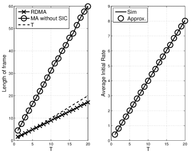
In Fig. 2, we show and for different values of when dB for independent Rayleigh fading channels. We can see that RDMA can provide a higher spectral efficiency than orthogonal multiple access.

We have the following remarks.
-
•
If channels are invariant within a frame, RDMA can exploit the channel reciprocity under A1) to take advantage of known CSI. In this case, as in PDMA, each active user can choose one of the available rates in according to the channel gain.
-
•
PDMA can also be used for block-fading channels where channel gains are varying for each slot. In this case, the transmission power is randomly chosen from a set of pre-determined powers.
VI Simulation Results
In this section, we present simulation results under A2) (i.e., for independent Rayleigh fading channels). For performance comparisons, we consider an RTxD random access scheme without SIC (but HARQ-IR is employed) [8], which has the length of frame in (13), and another random access scheme of re-transmissions of identical coded blocks based on [14], which has the length of frame in (14). For convenience, the former scheme is referred to as multiple access without SIC (MA without SIC) and the latter scheme is referred to as repetition with SIC.
Throughout this section, for PDMA, we assume that is decided to have . In addition, for RDMA, is set to .
Fig. 3 shows the average lengths of frame of PDMA, MA without SIC, and repetition with SIC for different values of when dB, , , , and (note that the value of is decided for given values of and from (25)). It is shown that PDMA can provide a smaller length of frame than the other schemes and the lengths of frame of all the schemes decrease with at the cost of the transmission power (as will be shown in Fig. 4 (a)). Since is set to 10, it is expected that the average length of frame of PDMA is smaller than 10. If is large (i.e., ), we can see that the average length of frame of PDMA can be smaller than 10. However, if is not large, there might be outage events that result in a longer length of frame than the desired one, 10.

In Fig. 4 (a), the average transmission power is shown for different values of . The transmission power increases with , which can be predicted by (34). As mentioned earlier, the lengths of frame of MA without SIC and repetition with SIC also decrease with as their transmission powers333For simulations of MA without SIC, we assume the same transmission power as that in PDMA. increase with . The probability of power collision decreases with in Fig. 4 (b) as expected by (37) (we note that (37) is a reasonable upper-bound on ).

(a) (b)
Fig. 5 shows the performances of PDMA for different values of when dB, , , , and . We can see that a large is desirable for a smaller length of frame of PDMA. In addition, the transmission power can be low at the cost of a longer transmission time.

(a) (b)
To see the impact of on the performances of PDMA, MA without SIC, and repetition with SIC, different values of are considered and simulation results are shown in Fig. 6 when dB, , , , and . As increases, the average lengths of frame of all the schemes increase as there are more active users, while PDMA could provide a lower length of frame than up to users. Note that since is fixed, as shown in Fig. 6 (b), the average transmission power is invariant with respect to .

(a) (b)
We now consider the performance of RDMA. Fig. 7 shows the performances of RDMA and MA without SIC for different values of when dB, , , and . RDMA performs better than MA without SIC in terms of the average length of frame as shown in Fig. 7 (a). In Fig. 7 (b), it is shown that the average initial rate decreases with , where the theoretical one is obtained from (42).

(a) (b)
To see the impact of on the performances of RDMA and MA without SIC, different values of are considered and simulation results are shown in Fig. 8 when dB, , , and . The gap between the average lengths of frame of RDMA and MA without SIC increases with as shown in Fig. 8 (a), which shows that RDMA performs much better than MA without SIC, especially for a large . We also see that the average length of frame of RDMA can be smaller than for large ’s, which demonstrates that RDMA can more likely guarantee that the required number of re-transmissions for successful decoding is less than or equal to when is sufficiently large.
(a) (b)
Finally, in Fig. 9, we show the normalized spectral efficiencies (i.e., the (average) initial rate per user over average length of frame) of PDMA, RDMA, and MA without SIC for different transmission powers with , dB, , , and . We can see that PDMA performs better than RDMA. This performance gain results from the power allocation with known CSI (in (24)) in PDMA. It is interesting to note that this gain vanishes when the transmission power is high. In both PDMA and RDMA, the spectral efficiency increases with the average transmission power. This implies that SIC can effectively mitigate interference from other active users. On the other hand, in MA without SIC, the increase of spectral efficiency becomes saturated when the transmission power increases. This saturation indicates that the spectral efficiency mainly depends on the MAI in MA without SIC and, as a result, the increase of the transmission power does not help improve the spectral efficiency unless some interference cancellation techniques (e.g., SIC) are employed.

VII Concluding Remarks
In this paper, we studied a multiple access scheme that are based on HARQ-IR and SIC to exploit RTxD and mitigate MAI, respectively. We found conditions that can guarantee a certain number of re-transmissions in the proposed multiple access scheme. Based on the derived conditions and two special cases, we considered two multichannel random access schemes, PDMA and RDMA, that have sub-channels in the power and rate domains, respectively. The analysis results showed that the proposed multiple access scheme can have a shorter length of frame than other existing similar schemes, which implies that the proposed multiple access scheme outperforms other existing ones in terms of the spectral efficiency. We also demonstrated that PDMA and RDMA can be used for coordinated multiple access. In this case, RDMA can have a higher spectral efficiency than orthogonal multiple access.
While we focused on some fundamental properties of the proposed multiple access schemes, we did not consider some possible extensions in this paper. For example, we may consider the case that the BS is equipped with multiple antennas (which may increase the spectral efficiency) and a hybrid approach of PDMA and RDMA in the future as further research topics.
Appendix A Proof of Lemma 1
The initial SINR is . The number of re-transmissions for stage 1 is
Thus, in stage 1, the signals of rate can be removed. Subsequently, we can show that
From this, we can see that the length of frame is the minimum positive integer of that satisfies (16).
Appendix B Proof of Lemma 2
From (17), it can be shown that the SINRs at stage 0 are given by
where , which demonstrates that the active user who will be decoded first is the user that has the highest channel gain, , since the rates are the same. Removing the signals from this user, we can also show that
From this, it is clear that the decoding order is the same as that in (17) (i.e., the order of the overall channel gains). Thus, at stage , from (19), the SINR of the signal to be decoded is given in (21). From this, we can see that the length of frame is the minimum positive integer of that satisfies (18).
Appendix C Proof of Lemma 3
Due to the power determination in (24), has to be one of , i.e., . In addition, since the ’s lie in different channel power regions and , , , should have different values. In addition, for the ordered overall channel gains, , since , we have . Note that the equality holds if . Thus, according to Lemma 2, the length of frame, , is less than or equal to , which completes the proof.
Appendix D Proof of Lemma 4
Appendix E Proof of Lemma 5
Using Jensen’s inequality, we can show that
Under A3), since is a binomial random variable, we have . From this, we can have (37).
Appendix F Proof of Lemma 6
Suppose that the active user who has the lowest initial rate is user . It can be shown that the sum rate of this user after re-transmissions is given by
which has the same statistical properties as those of as . Furthermore, user has the lowest rate among active users and all the rates are different, the rate of user has to be equal to or less than , i.e., . From (44), we have
| (49) |
Thus, at time (or after re-transmissions), the signals from user can be decoded and removed by SIC with a probability equal to or higher than .
Once user is removed, the user of the second lowest initial rate, which is less than or equal to , may have interfering signals. The sum rate of this user might be . Thus, as in (49), we can show that the signals from this user can be decoded and removed by SIC with a probability equal to or higher than . Consequently, all the signals from active users can be decoded within re-transmissions with a probability equal to or higher than .
Appendix G Proof of Lemma 7
Suppose that the number of active users in RDMA, , becomes and all users have different rates. Then, from (41), under A2a), the average rate of RDMA per user becomes . This is the maximum rate of RDMA as there are no outage events, which implies that
| (50) |
For orthogonal multiple access, we assume that the time slot is divided into sub-slots and in each sub-slot, one user can transmit signals using HARQ-IR without any interference. In this case, according to [8], for a large , the average (achievable) rate per user (with re-transmissions) becomes
| (51) |
with a high probability , where is decided to be times higher than that in RDMA (i.e., ) to have the same total power. From (50) and (51), we can have (46), which completes the proof.
Appendix H Proof of Lemma 8
Consider an optimization problem as follows:
| (52) | |||
| (53) |
where the ’s are iid and as in A2a). For convenience, assume that for all . If for all , becomes . On the other hand, if and , it becomes .
Since is concave, the maximum exists. To find the optimal solution, with a Lagrange multiplier, , we can show that the following equality has to be satisfied for all :
From this, since is symmetric with respect to , we can see that the optimal solution becomes . Thus, is the maximum, which implies (47).
References
- [1] D. Tse and P. Viswanath, Fundamentals of Wireless Communication. Cambridge University Press, 2005.
- [2] B. Bertsekas and R. Gallager, Data Networks. Englewood Cliffs: Prentice-Hall, 1987.
- [3] N. Abramson, “The throughput of packet broadcasting channels,” IEEE Trans. Communications, vol. 25, pp. 117–128, Jan 1977.
- [4] L. Kleinrock and F. Tobagi, “Packet switching in radio channels: Part i - carrier sense multiple-access modes and their throughput-delay characteristics,” IEEE Trans. Communications, vol. 23, pp. 1400–1416, December 1975.
- [5] M. K. Tsatsanis, R. Zhang, and S. Banerjee, “Network-assisted diversity for random access wireless networks,” IEEE Trans. Signal Processing, vol. 48, pp. 702–711, Mar 2000.
- [6] S. Lin and D. J. Costello, Jr, Error Control Coding: Fundamentals and Applications. Englewood Cliffs, N.J.: Prentice Hall, 1983.
- [7] S. B. Wicker, Error Control Systems for Digital Communication and Storage. Prentice Hall, 1995.
- [8] G. Caire and D. Tuninetti, “The throughput of hybrid-ARQ protocols for the Gaussian collision channel,” IEEE Trans. Inform. Theory, vol. 47, pp. 1971–1988, July 2001.
- [9] C. Shen, T. Liu, and M. P. Fitz, “On the average rate performance of hybrid-ARQ in quasi-static fading channels,” IEEE Trans. Communications, vol. 57, pp. 3339–3352, Nov 2009.
- [10] P. Wu and N. Jindal, “Performance of hybrid-ARQ in block-fading channels: a fixed outage probability,” IEEE Trans. Communications, vol. 58, pp. 1129–1141, Apr. 2010.
- [11] P. Larsson, L. K. Rasmussen, and M. Skoglund, “Throughput analysis of ARQ schemes in gaussian block fading channels,” IEEE Trans. Communications, vol. 62, pp. 2569–2588, July 2014.
- [12] B. Makki, T. Svensson, T. Eriksson, and M. S. Alouini, “Coordinated hybrid automatic repeat request,” IEEE Communications Letters, vol. 18, pp. 1975–1978, Nov 2014.
- [13] G. Choudhury and S. Rappaport, “Diversity aloha - a random access scheme for satellite communications,” IEEE Trans. Communications, vol. 31, pp. 450–457, March 1983.
- [14] E. Casini, R. D. Gaudenzi, and O. D. R. Herrero, “Contention resolution diversity slotted ALOHA (CRDSA): An enhanced random access schemefor satellite access packet networks,” IEEE Trans. Wireless Communications, vol. 6, pp. 1408–1419, April 2007.
- [15] G. Liva, “Graph-based analysis and optimization of contention resolution diversity slotted ALOHA,” IEEE Trans. Communications, vol. 59, pp. 477–487, February 2011.
- [16] J. Choi, J. Ha, and H. Jeon, “On the energy delay tradeoff of HARQ-IR in wireless multiuser systems,” IEEE Trans. Commununications, vol. 61, pp. 3518–3529, August 2013.
- [17] M. Mitzenmacher and E. Upfal, Probability and Computing: Randomized Algorithms and Probability Analysis. Cambridge University Press, 2005.
- [18] Y.-J. Choi, S. Park, and S. Bahk, “Multichannel random access in ofdma wireless networks,” IEEE J. Selected Areas in Communications, vol. 24, pp. 603–613, March 2006.
- [19] J. Choi, “On the adaptive determination of the number of preambles in RACH for MTC,” IEEE Communications Letters, vol. 20, pp. 1385–1388, July 2016.
- [20] M.-S. Alouini and A. J. Goldsmith, “Capacity of Rayleigh fading channels under different adaptive transmission and diversity-combining techniques,” IEEE Trans. Veh. Technol., vol. 48, pp. 1165–1181, July 1999.
- [21] H. Shin and J. H. Lee, “Capacity of multiple-antenna fading channels: Spatial fading correlation, double scattering, and keyhole,” IEEE Trans. Inform. Theory, vol. 49, pp. 2636–2647, Oct. 2003.
- [22] T. M. Cover and J. A. Thomas, Elements of Information Theory. NJ: John Wiley, second ed., 2006.