Quantum Magnetometer with Dual-Coupling Optomechanics
Abstract
An experimentally feasible magnetometer based on a dual-coupling optomechanical system is proposed, where the radiation-pressure coupling transduces the magnetic signal to the optical phase, and the quadratic optomechanical interaction induces a periodic squeezing effect. The latter not only amplifies the signal to be measured, but also accelerates the signal transducing rate characterized by an experimentally observable phase accumulation efficiency. In the vicinity of opto-mechanical decoupled time, the ultimate bound to the estimability of magnetic signal is proportional to , and then the optimized accuracy of estimation can be enhanced nearly 3 orders with a controllable squeezing parameter . Moreover, our proposal is robust against the mechanical thermal noise, and the sensitivity of a specific measurement can reach to the order of in the presence of dissipations and without ground state cooling of mechanical oscillator. Our proposal fundamentally broadens the fields of quantum metrology and cavity optomechanics, with potential application for on-chip magnetic detection with high precision.
Ultrasensitive magnetic detection has contributed immensely to a wide range of scientific areas from fundamental physics to advanced technologies, such as geological exploration, aerospace Bennett et al. (2021), biomedical imaging and diagnostics Hämäläinen et al. (1993); Lee et al. (2015); Murzin et al. (2020). Over the past few decades, various magnetometers have been developed, including the superconducting quantum interference devices (SQUID) based on superconducting effects Jaklevic et al. (1964); Erné et al. (1976); Kleiner et al. (2004), spin-exchange relaxation-free atomic magnetometers Allred et al. (2002); Kominis et al. (2003); Savukov et al. (2005); Xia et al. (2006), NV center magnetometers Taylor et al. (2008); Maze et al. (2008) and Hall-effect sensors Bending (1999). Normally, they require the elaborated operating conditions, such as the associated denoising technology and/or the complex signal read-out schemes Robbes (2006), which reduces their capability of on-chip integration.
Cavity optomechanical system (OMS) Aspelmeyer et al. (2014); Kippenberg and Vahala (2008); Aspelmeyer et al. (2012); Meystre (2013) offers an alternative platform for the precision measurements of mass Li and Zhu (2012); Lin et al. (2017); Bin et al. (2019), weak forces Clerk et al. (2010); Tsang and Caves (2010); Pontin et al. (2014); Armata et al. (2017); Qvarfort et al. (2018), and magnetic fields Forstner et al. (2012, 2014); Yu et al. (2016); Wu et al. (2017); Zhu et al. (2017); Li et al. (2018). Particularly, optomechanical magnetometer with high sensitivity has excellent quality of on-chip integration Li et al. (2021). Recently, the YIG sphere-based optomechanical magnetometer has been experimentally demonstrated in Ref. Colombano et al. (2020), which have attained extremely low sensitivity values. In such magnetometers, the existence of Joule and Villari effects of magnetostrictive transducer Olabi and Grunwald (2008), allows one to directly extract magnetic information by reading out the optical frequency shift (or transmission spectrum). Moreover, quantum metrology Giovannetti et al. (2004, 2006, 2011); Dowling and Seshadreesan (2015) points out that the quantum squeezing or entanglement Caves (1981); Ma et al. (2011); Baumgratz and Datta (2016); Degen et al. (2017); Engelsen et al. (2017); Nagata et al. (2007); Israel et al. (2014); Luo et al. (2017) could improve the accuracy of parameter estimation in physical systems from the shot-noise limit to the Heisenberg limit, i.e., the optimal precision scales from to with being the number of resources employed in the measurements. This has stimulated enormous interests in exploiting quantum resources in the atoms (or spins) Jones et al. (2009); Tanaka et al. (2015); Kómár et al. (2014); Hou et al. (2020) and optical systems Holland and Burnett (1993); Boto et al. (2000); Anisimov et al. (2010); Joo et al. (2011) for high-precision physical quantity measurements.
By applying quantum metrology to the detection of a static magnetic field, here we propose a quantum magnetometer based on a dual-coupling OMS, which has a periodic decoupling behavior between the optical and mechanical modes. The OMS supports two optical modes coupled simultaneously to the same mechanical mode, with radiation-pressure and quadratic optomechanical interactions, respectively Thompson et al. (2008); Sankey et al. (2010); Bhattacharya et al. (2008); Zhu et al. (2018). The radiation-pressure coupling acts as a signal transducer, encoding the magnetic signal received by the mechanical oscillator into the optical phase. The quadratic optomechanical interaction amplifies both the signal to be measured and the signal transducing rate via inducing a periodic squeezing effect on the mechanical oscillator, whose maximum squeezing strength is determined by a controllable squeezing parameter . By performing a homodyne detection on the optical phase within a wide time window around the first decoupled time , the magnetic signal could be estimated with high precision.
To qualitatively characterize the precision of magnetometer, we define a displaced phase accumulation efficiency (PAE) that is experimentally observable via state tomography technique. By presenting the exponentially increased quantum Fisher information (QFI), i.e., , we quantitatively demonstrate that the fundamental bound of measurement precision can be dramatically reduced even with a small squeezing parameter . The periodic opto-mechanical decoupling makes the classical Fisher information (CFI) robust against the mechanical environment at the decoupled time, which in turn allows the sensitivity of a specific measurement to saturate the fundamental bound and reach to the order of in the presence of system dissipations. Moreover, the sensitivity to the order of is predicted even in the case of the thermal phonon number . Our work establishes a connection between quantum metrology and dual-coupling optomechanics, which is suitable for detecting various fields that linearly interact with the mechanical oscillator.
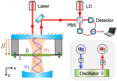
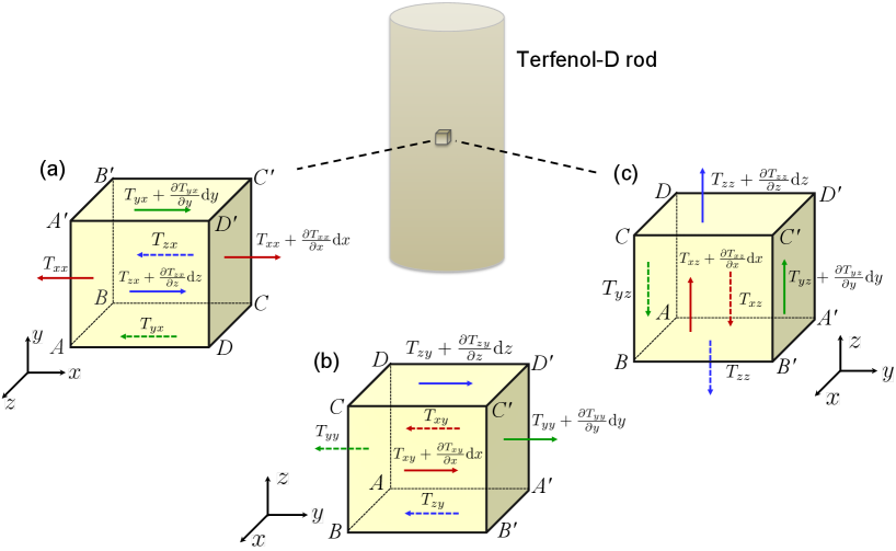
System and periodic mechanical squeezing.— We consider a dual-coupling optomechanical system depicted in Fig. 1 with Hamiltonian
| (1) |
where and are the annihilation operators of the cavity mode with frequency and the mechanical mode with frequency , respectively. The mechanical membrane is placed at a node (antinode) of cavity mode (), and then the fourth (fifth) term in Eq. (1) describes the radiation-pressure (quadratic optomechanical) interaction between modes () and with strength (). In the presence of a static magnetic field (along direction), the field-sensitive Terfenol-D expands, which leads to the change of the equilibrium position of the mechanical oscillator, thus generating an effective magnetic potential on the Hamiltonian, i.e., the last term of Equation (1) SM . The mechanical motion modulates the optical cavity field via the nonlinear radiation-pressure coupling. Meanwhile, the phase shift of the mechanical motions encoded with magnetic signal is transferred to the optical field. By reading out the phase shift of optical field via homodyne detection, we can extract the original magnetic information. Here is the position operator of the mechanical oscillator with mass , and is the magnetic actuation constant charactering how well the magnetic field is converted into a force applied on the oscillator. The symbol denotes the length of Terfenol-D rods, is magnetostrictive coefficient and is the Young’s modulus SM .
By considering the ancillary mode in the coherent state , the number operator can be approximately replaced by an algebraic number in the case of SM . Assuming the modes and are initially in the coherent state with , the instantaneous state of system is given by SM
| (2) |
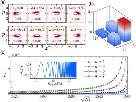
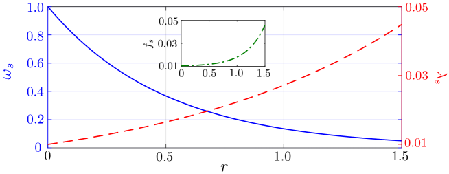
where with , , , , and a rotating frame with was adopted. The mechanical state reads with the defined squeezing operator and the squeezing parameter . Here is a displaced coherent state with . The expression of clearly shows that the mechanical mode is dynamically squeezed with the period , whose squeezing degree of quadrature is defined by . The maximum squeezing degree occurs at with the state SM . This periodic squeezing effect on the mechanical oscillator is induced by the quadratic optomechanical coupling, and can be qualitatively presented in the case of [see Fig. 2(a)].
Periodic-squeezing-enhanced phase accumulation efficiency.— As shown in Eq. (Quantum Magnetometer with Dual-Coupling Optomechanics), the magnetic signal is transduced into the optical phase during the evolution of system via the radiation-pressure interaction. Interestingly, at time (), Eq. (Quantum Magnetometer with Dual-Coupling Optomechanics) can be reduced to SM
| (3) |
which demonstrates that the optical and mechanical modes are periodically decoupled, meanwhile the magnetic signal to be measured is periodically encoded into the accumulated optical phase for a Fock state . Here the opto-mechanical decoupled period is double of the period of dynamical squeezing, i.e., , and hence the mechanical squeezing also disappears at the decoupled time .
The above unique property allows us to estimate the magnetic field by performing a homodyne detection [see Fig. 1] on the optical mode at the first decoupled time . To qualitatively describe the detection precision, here we define a displaced PAE
| (4) |
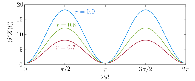
Obviously, the larger , i.e., the faster phase accumulation rate on the optical Fock state , the higher measurement accuracy of magnetometer should be obtained. As shown in Fig. 2(c), the is exponentially enhanced by increasing the coherent amplitude of the ancillary mode . This enhancement originally comes from the periodic squeezing of mechanical mode during one opto-mechanical decoupled period [see Fig. 2(a)]. The system Hamiltonian in the squeezed frame shown in Eq. (S17) of supplementary material SM clearly demonstrates that the mechanical squeezing effect not only accelerates the signal tranducing rate from phonon to photon (i.e., the radiation-pressure interaction ) Lü et al. (2015); Lemonde et al. (2016), but also amplifies the magnetic signal to be measured (i.e., the magnetic potential ).
More importantly, this well-defined PAE is experimentally observable via state tomography in the proper basis vectors. Specifically, expanding the system state in the subspace with basis vectors and (), we obtain four elements of density matrix SM , as shown in Fig. 2(b). The difference between two diagonal elements is denoted by , where . Then one can easily obtain the values of phase difference by directly measuring and , which ultimately leads to being experimentally observable. Moreover, the oscillation with increasing frequency of , shown in the insert of Fig. 2(c), is another evidence for the enhanced along with increasing the mechanical squeezing.
Quantum and classical Fisher information.— From a quantitative point of view, the fundamental bound to the sensitivity and the measurement-specific sensitivity of the proposed magnetometer are respectively decided by the QFI and CFI based on the Cramér-Rao inequality , where is the standard deviation with respect to an unbiased estimator , and is the number of repetition of the experiments Braunstein and Caves (1994).
Considering system state , the QFI with respect to the parameter reads , where Paris (2009); Tóth and Apellaniz (2014); Liu et al. (2019); Lu and Wang (2021); Liu et al. (2022). At the first decoupled time , the QFI reduces to SM
| (5) |
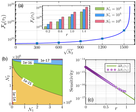
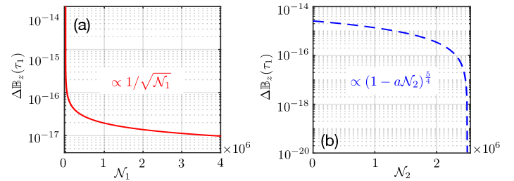
where is the mean photon number of cavity mode . It can be seen that the QFI is exponentially enhanced with power of , and hence increasing a small value of by changing can give rise to a large enhancement of the QFI. Figure 3(a) shows an enhancement with 7 orders of magnitude for the QFI, corresponding to a dramatic reduction of the optimal sensitivity . As shown in Fig. 3(b), the optimal sensitivity can reach to the order of for a wide parameter region in terms of the mean photon numbers and . Equation (Quantum Magnetometer with Dual-Coupling Optomechanics) also indicates that the resources and exert different influences on the ultimate lower bound of sensitivity SM . We note that the QFI at does not depend on the actual value of .
Next, let us calculate the CFI related to a specific measurement on the quadrature , where is the phase of local oscillator. At the first decoupled time , the CFI is given by SM
| (6) |
Evidently, it consists precisely with the QFI shown in Eq. (Quantum Magnetometer with Dual-Coupling Optomechanics) when () and is a real (imaginary) number, which means that the momentum (position) measurement can saturate the optimal sensitivity in the absence of system dissipation.
In the practical situation, the dissipation caused by the system-bath coupling should be taken into account. Then the dynamics of system is dominated by the master equation
| (7) |
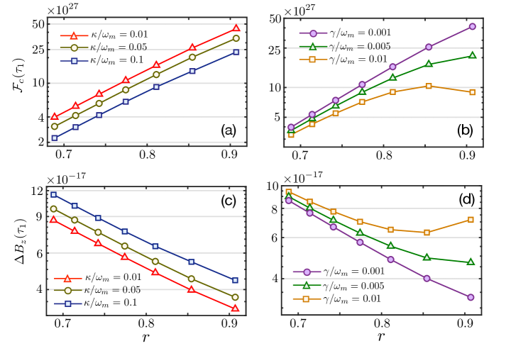
where is the cavity (mechanical) decay rate, is the thermal phonon number of the mechanical mode, and . Here we have considered the cavity mode being in the coherent state for Hamiltonian . Performing a momentum homodyne measurement (i.e., ) on cavity , in Fig. 3(c) and Fig. 4, we numerically demonstrate the influence of system dissipation on the sensitivity limit, i.e., , of magnetometer Johansson et al. (2012).
With the practical experimental parameters, Figure 3(c) shows that the specific sensitivity obtained in the presence of system decay and noise, still can fit well with the optimal one from the QFI without system dissipation. This consistency is only broken weakly when one increases the squeezing parameter to a large value. This can be explained as follows. On the one hand, system dissipation has little effect on the CFI in the case of weak squeezing parameter [see the inserts of Fig. 4]. More importantly, the periodic optomechanical decoupling makes the CFI robust against the mechanical thermal noise. As shown in Fig. 4(b), a high sensitivity reaching to the order of is allowed even when . This means that the mechanical ground state cooling is not necessary for obtaining high-precision magnetometer in our proposal. On the other hand, the strong mechanical squeezing amplifies the effect of mechanical dissipation on CFI via effectively heating the environment (see the insert of Fig. 4(b) and Fig. S5 in supplementary material SM ), which leads to the weak disagreement between the measurement-specific sensitivity limit and the fundamental bound of sensitivity in the case of large values of .
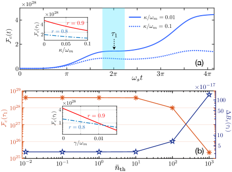
Discussion of experimental feasibility.— Regarding experimental implementations, while we have considered here a Febry-Pérot cavity with the membrane-in-the-middle configuration, our versatile proposal is not limited to this particular architecture. Based on the excellent controllability of the SQUID You and Nori (2011); Xiang et al. (2013), the transmission-line (TL) resonator coupled to a SQUID-terminated TL resonator is a promising platform to realize dual-coupling optomechanical system Johansson et al. (2014); Kim et al. (2015). Recently, the dual-coupling optomechanics was also demonstrated in photonic crystal cavities Kalaee et al. (2016); Brunelli et al. (2018) and whispering gallery microcavities Li et al. (2012). Based on recent optomechanical experiments Thompson et al. (2008); Sankey et al. (2010); Ockeloen-Korppi et al. (2018), here the system parameters can be chosen as g, kHz, kHz, Hz, kHz, Hz, and . Then, with a cycle time on tens of s, our work theoretically predicts that the sensitivity in the range of can be realized with the achievable squeezing parameter . Note that most of the above results are obtained in the case of performing the homodyne measurement at the first decoupled time . Fortunately, our proposal is robust against the detection time, i.e., the CFI in the vicinity of is nearly flat as shown in Figure 4(a). In other words, our proposal exhibits a wide time-window to perform measurement with sensitivity reaching to the order of .
Moreover, the experimental implementation of our proposal relies on the thin membrane held by Terfenol-D rods, which gives an effective magnetic potential on the Hamiltonian. The conversion efficiency from the applied magnetic field to an effective force on the mechanical oscillator, is determined by the magnetic actuation constant . The precise experimental determination of the magnetic actuation constant is of key importance for measuring afterwards accurate values of the magnetic field. This magnetic constant depends heavily on the specific geometrical configuration of the rods with respect to the membrane. To optimize the magnetostrictive effect, the applied magnetic field needs to be paralleled to the magnetostricitive direction of the Terfenol-D rods. In addition, here we considered the Terfenol-D rods of the length m, thus it is approximatively valid to consider the magnetostrictive material to be in the whole homogeneous magnetic field, which also allows the system to have a large actuation constant.
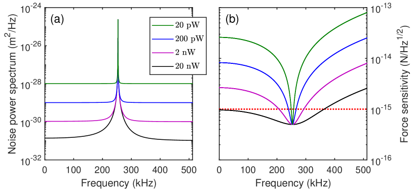
Despite here we focus on detecting a static magnetic field, our proposal, in principle, can also be applied to probe the alternating magnetic fields. The corresponding frequency response characteristics are discussed in Sec. VII of the supplementary material SM . Referring to the parameters used in optomechanical experiments Li et al. (2021); Thompson et al. (2008), we numerically simulate the displacement noise power spectrum and the corresponding force sensitivity at different probe powers (see Fig. S6 in the supplementary material). We find that the thermal-noise-limited frequency range covers kHz with the central resonant frequency 250 kHz in the case of the probe power at . Therefore, similar as a general optomechanical system Li et al. (2021), here the dual-coupling magnetometer also has a broad bandwidth, when it is used as a resonant sensor.
Conclusions.– We have presented a protocol to measure the weak magnetic field using dual-coupling optomechanics. The sensitivity could be enhanced to the order of by adjusting the photon numbers of two cavity modes. This enhancement originally comes from the periodic mechanical squeezing, which greatly amplifies both the signal to be measured and the transducing rate of signal. We stress out that this periodic squeezing effect is self-sustained, which avoids the complicated process of preparing squeezed states. Our proposal, with wide time-window of detection, is robust against the mechanical thermal noise, and hence the ground state cooling of mechanical mode is not necessary. This work might inspire the studies of high-precision measurements of various physical quantities based on dual-coupling optomechanical systems.
Acknowledgments.–We thank Bei-Bei Li for fruitful discussions and valuable comments. This work is supported by the National Key Research and Development Program of China grant 2021YFA1400700 and the National Science Foundation of China (Grant Nos. 11822502, 11974125, 11875029, 12175075 and 11805073).
References
- Bennett et al. (2021) J. S. Bennett, B. E. Vyhnalek, H. Greenall, E. M. Bridge, F. Gotardo, S. Forstner, G. I. Harris, F. A. Miranda, and W. P. Bowen, Precision magnetometers for aerospace applications: A review, Sensors 21, 5568 (2021).
- Hämäläinen et al. (1993) M. Hämäläinen, R. Hari, R. J. Ilmoniemi, J. Knuutila, and O. V. Lounasmaa, Magnetoencephalography-theory, instrumentation, and applications to noninvasive studies of the working human brain, Rev. Mod. Phys. 65, 413 (1993).
- Lee et al. (2015) H. Lee, T.-H. Shin, J. Cheon, and R. Weissleder, Recent developments in magnetic diagnostic systems, Chem. Rev. 115, 10690 (2015).
- Murzin et al. (2020) D. Murzin, D. J. Mapps, K. Levada, V. Belyaev, A. Omelyanchik, L. Panina, and V. Rodionova, Ultrasensitive magnetic field sensors for biomedical applications, Sensors 20, 1569 (2020).
- Jaklevic et al. (1964) R. C. Jaklevic, J. Lambe, A. H. Silver, and J. E. Mercereau, Quantum interference effects in josephson tunneling, Phys. Rev. Lett. 12, 159 (1964).
- Erné et al. (1976) S. N. Erné, H.-D. Hahlbohm, and H. Lübbig, Theory of rf-biased superconducting quantum interference device for nonhysteretic regime, J. Appl. Phys. 47, 5440 (1976).
- Kleiner et al. (2004) R. Kleiner, D. Koelle, F. Ludwig, and J. Clarke, Superconducting quantum interference devices: State of the art and applications, Proceedings of the IEEE 92, 1534 (2004).
- Allred et al. (2002) J. C. Allred, R. N. Lyman, T. W. Kornack, and M. V. Romalis, High-sensitivity atomic magnetometer unaffected by spin-exchange relaxation, Phys. Rev. Lett. 89, 130801 (2002).
- Kominis et al. (2003) I. K. Kominis, T. W. Kornack, J. C. Allred, and M. V. Romalis, A subfemtotesla multichannel atomic magnetometer, Nature 422, 596 (2003).
- Savukov et al. (2005) I. M. Savukov, S. J. Seltzer, M. V. Romalis, and K. L. Sauer, Tunable atomic magnetometer for detection of radio-frequency magnetic fields, Phys. Rev. Lett. 95, 063004 (2005).
- Xia et al. (2006) H. Xia, A. Ben-Amar Baranga, D. Hoffman, and M. V. Romalis, Magnetoencephalography with an atomic magnetometer, Appl. Phys. Lett. 89, 211104 (2006).
- Taylor et al. (2008) J. M. Taylor, P. Cappellaro, L. Childress, L. Jiang, D. Budker, P. R. Hemmer, A. Yacoby, R. Walsworth, and M. D. Lukin, High-sensitivity diamond magnetometer with nanoscale resolution, Nat. Phys. 4, 810 (2008).
- Maze et al. (2008) J. R. Maze, P. L. Stanwix, J. S. Hodges, S. Hong, J. M. Taylor, P. Cappellaro, L. Jiang, M. V. G. Dutt, E. Togan, A. S. Zibrov, A. Yacoby, R. L. Walsworth, and M. D. Lukin, Nanoscale magnetic sensing with an individual electronic spin in diamond, Nature 455, 644 (2008).
- Bending (1999) S. J. Bending, Local magnetic probes of superconductors, Advances in Physics 48, 449 (1999).
- Robbes (2006) D. Robbes, Highly sensitive magnetometers—a review, Sens. Actu. A: Phys. 129, 86 (2006).
- Aspelmeyer et al. (2014) M. Aspelmeyer, T. J. Kippenberg, and F. Marquardt, Cavity optomechanics, Rev. Mod. Phys. 86, 1391 (2014).
- Kippenberg and Vahala (2008) T. J. Kippenberg and K. J. Vahala, Cavity optomechanics: Back-action at the mesoscale, Science 321, 1172 (2008).
- Aspelmeyer et al. (2012) M. Aspelmeyer, P. Meystre, and K. Schwab, Quantum optomechanics, Physics Today 65, 29 (2012).
- Meystre (2013) P. Meystre, A short walk through quantum optomechanics, Ann. Phys. 525, 215 (2013).
- Li and Zhu (2012) J.-J. Li and K.-D. Zhu, Nonlinear optical mass sensor with an optomechanical microresonator, Appl. Phys. Lett. 101, 141905 (2012).
- Lin et al. (2017) Q. Lin, B. He, and M. Xiao, Mass sensing by detecting the quadrature of a coupled light field, Phys. Rev. A 96, 043812 (2017).
- Bin et al. (2019) S.-W. Bin, X.-Y. Lü, T.-S. Yin, G.-L. Zhu, Q. Bin, and Y. Wu, Mass sensing by quantum criticality, Opt. Lett. 44, 630 (2019).
- Clerk et al. (2010) A. A. Clerk, M. H. Devoret, S. M. Girvin, F. Marquardt, and R. J. Schoelkopf, Introduction to quantum noise, measurement, and amplification, Rev. Mod. Phys. 82, 1155 (2010).
- Tsang and Caves (2010) M. Tsang and C. M. Caves, Coherent quantum-noise cancellation for optomechanical sensors, Phys. Rev. Lett. 105, 123601 (2010).
- Pontin et al. (2014) A. Pontin, M. Bonaldi, A. Borrielli, F. S. Cataliotti, F. Marino, G. A. Prodi, E. Serra, and F. Marin, Detection of weak stochastic forces in a parametrically stabilized micro-optomechanical system, Phys. Rev. A 89, 023848 (2014).
- Armata et al. (2017) F. Armata, L. Latmiral, A. D. K. Plato, and M. S. Kim, Quantum limits to gravity estimation with optomechanics, Phys. Rev. A 96, 043824 (2017).
- Qvarfort et al. (2018) S. Qvarfort, A. Serafini, P. F. Barker, and S. Bose, Gravimetry through non-linear optomechanics, Nat. Commun. 9, 3690 (2018).
- Forstner et al. (2012) S. Forstner, S. Prams, J. Knittel, E. D. van Ooijen, J. D. Swaim, G. I. Harris, A. Szorkovszky, W. P. Bowen, and H. Rubinsztein-Dunlop, Cavity optomechanical magnetometer, Phys. Rev. Lett. 108, 120801 (2012).
- Forstner et al. (2014) S. Forstner, E. Sheridan, J. Knittel, C. L. Humphreys, G. A. Brawley, H. Rubinsztein-Dunlop, and W. P. Bowen, Ultrasensitive optomechanical magnetometry, Adv. Mater. 26, 6348 (2014).
- Yu et al. (2016) C. Yu, J. Janousek, E. Sheridan, D. L. McAuslan, H. Rubinsztein-Dunlop, P. K. Lam, Y. Zhang, and W. P. Bowen, Optomechanical magnetometry with a macroscopic resonator, Phys. Rev. Appl. 5, 044007 (2016).
- Wu et al. (2017) M. Wu, N. L.-Y. Wu, T. Firdous, F. Fani Sani, J. E. Losby, M. R. Freeman, and P. E. Barclay, Nanocavity optomechanical torque magnetometry and radiofrequency susceptometry, Nat. Nanotech. 12, 127 (2017).
- Zhu et al. (2017) J. Zhu, G. Zhao, I. Savukov, and L. Yang, Polymer encapsulated microcavity optomechanical magnetometer, Sci. Rep. 7, 8896 (2017).
- Li et al. (2018) B.-B. Li, J. Bílek, U. B. Hoff, L. S. Madsen, S. Forstner, V. Prakash, C. Schäfermeier, T. Gehring, W. P. Bowen, and U. L. Andersen, Quantum enhanced optomechanical magnetometry, Optica 5, 850 (2018).
- Li et al. (2021) B.-B. Li, L. Ou, Y. Lei, and Y.-C. Liu, Cavity optomechanical sensing, Nanophotonics 10, 2799 (2021).
- Colombano et al. (2020) M. F. Colombano, G. Arregui, F. Bonell, N. E. Capuj, E. Chavez-Angel, A. Pitanti, S. O. Valenzuela, C. M. Sotomayor-Torres, D. Navarro-Urrios, and M. V. Costache, Ferromagnetic resonance assisted optomechanical magnetometer, Phys. Rev. Lett. 125, 147201 (2020).
- Olabi and Grunwald (2008) A. Olabi and A. Grunwald, Design and application of magnetostrictive materials, Materials & Design 29, 469 (2008).
- Giovannetti et al. (2004) V. Giovannetti, S. Lloyd, and L. Maccone, Quantum-enhanced measurements: Beating the standard quantum limit, Science 306, 1330 (2004).
- Giovannetti et al. (2006) V. Giovannetti, S. Lloyd, and L. Maccone, Quantum metrology, Phys. Rev. Lett. 96, 010401 (2006).
- Giovannetti et al. (2011) V. Giovannetti, S. Lloyd, and L. Maccone, Advances in quantum metrology, Nat. Photon. 5, 222 (2011).
- Dowling and Seshadreesan (2015) J. P. Dowling and K. P. Seshadreesan, Quantun optical technologies for metrology, sensing, and imaging, J. Lightwave Technol. 33, 2359 (2015).
- Caves (1981) C. M. Caves, Quantum-mechanical noise in an interferometer, Phys. Rev. D 23, 1693 (1981).
- Ma et al. (2011) J. Ma, X. Wang, C. Sun, and F. Nori, Quantum spin squeezing, Phys. Rep. 509, 89 (2011).
- Baumgratz and Datta (2016) T. Baumgratz and A. Datta, Quantum enhanced estimation of a multidimensional field, Phys. Rev. Lett. 116, 030801 (2016).
- Degen et al. (2017) C. L. Degen, F. Reinhard, and P. Cappellaro, Quantum sensing, Rev. Mod. Phys. 89, 035002 (2017).
- Engelsen et al. (2017) N. J. Engelsen, R. Krishnakumar, O. Hosten, and M. A. Kasevich, Bell correlations in spin-squeezed states of 500 000 atoms, Phys. Rev. Lett. 118, 140401 (2017).
- Nagata et al. (2007) T. Nagata, R. Okamoto, J. L. O’Brien, K. Sasaki, and S. Takeuchi, Beating the standard quantum limit with four-entangled photons, Science 316, 726 (2007).
- Israel et al. (2014) Y. Israel, S. Rosen, and Y. Silberberg, Supersensitive polarization microscopy using noon states of light, Phys. Rev. Lett. 112, 103604 (2014).
- Luo et al. (2017) X.-Y. Luo, Y.-Q. Zou, L.-N. Wu, Q. Liu, M.-F. Han, M. K. Tey, and L. You, Deterministic entanglement generation from driving through quantum phase transitions, Science 355, 620 (2017).
- Jones et al. (2009) J. A. Jones, S. D. Karlen, J. Fitzsimons, A. Ardavan, S. C. Benjamin, G. A. D. Briggs, and J. J. L. Morton, Magnetic field sensing beyond the standard quantum limit using 10-spin noon states, Science 324, 1166 (2009).
- Tanaka et al. (2015) T. Tanaka, P. Knott, Y. Matsuzaki, S. Dooley, H. Yamaguchi, W. J. Munro, and S. Saito, Proposed robust entanglement-based magnetic field sensor beyond the standard quantum limit, Phys. Rev. Lett. 115, 170801 (2015).
- Kómár et al. (2014) P. Kómár, E. M. Kessler, M. Bishof, L. Jiang, A. S. Sørensen, J. Ye, and M. D. Lukin, A quantum network of clocks, Nat. Phys. 10, 582 (2014).
- Hou et al. (2020) Z. Hou, Z. Zhang, G.-Y. Xiang, C.-F. Li, G.-C. Guo, H. Chen, L. Liu, and H. Yuan, Minimal tradeoff and ultimate precision limit of multiparameter quantum magnetometry under the parallel scheme, Phys. Rev. Lett. 125, 020501 (2020).
- Holland and Burnett (1993) M. J. Holland and K. Burnett, Interferometric detection of optical phase shifts at the heisenberg limit, Phys. Rev. Lett. 71, 1355 (1993).
- Boto et al. (2000) A. N. Boto, P. Kok, D. S. Abrams, S. L. Braunstein, C. P. Williams, and J. P. Dowling, Quantum interferometric optical lithography: Exploiting entanglement to beat the diffraction limit, Phys. Rev. Lett. 85, 2733 (2000).
- Anisimov et al. (2010) P. M. Anisimov, G. M. Raterman, A. Chiruvelli, W. N. Plick, S. D. Huver, H. Lee, and J. P. Dowling, Quantum metrology with two-mode squeezed vacuum: Parity detection beats the heisenberg limit, Phys. Rev. Lett. 104, 103602 (2010).
- Joo et al. (2011) J. Joo, W. J. Munro, and T. P. Spiller, Quantum metrology with entangled coherent states, Phys. Rev. Lett. 107, 083601 (2011).
- Thompson et al. (2008) J. D. Thompson, B. M. Zwickl, A. M. Jayich, F. Marquardt, S. M. Girvin, and J. G. E. Harris, Strong dispersive coupling of a high-finesse cavity to a micromechanical membrane, Nature 452, 72 (2008).
- Sankey et al. (2010) J. C. Sankey, C. Yang, B. M. Zwickl, A. M. Jayich, and J. G. E. Harris, Strong and tunable nonlinear optomechanical coupling in a low-loss system, Nat. Phys. 6, 707 (2010).
- Bhattacharya et al. (2008) M. Bhattacharya, H. Uys, and P. Meystre, Optomechanical trapping and cooling of partially reflective mirrors, Phys. Rev. A 77, 033819 (2008).
- Zhu et al. (2018) G.-L. Zhu, X.-Y. Lü, L.-L. Wan, T.-S. Yin, Q. Bin, and Y. Wu, Controllable nonlinearity in a dual-coupling optomechanical system under a weak-coupling regime, Phys. Rev. A 97, 033830 (2018).
- Hong (2013) C. Hong, Application of a magnetostrictive actuator, Materials and Design 46, 617 (2013).
- (62) See more information in Supplementary Material.
- Lü et al. (2015) X.-Y. Lü, Y. Wu, J. R. Johansson, H. Jing, J. Zhang, and F. Nori, Squeezed optomechanics with phase-matched amplification and dissipation, Phys. Rev. Lett. 114, 093602 (2015).
- Lemonde et al. (2016) M.-A. Lemonde, N. Didier, and A. A. Clerk, Enhanced nonlinear interactions in quantum optomechanics via mechanical amplification, Nat. Commun. 7, 11338 (2016).
- Braunstein and Caves (1994) S. L. Braunstein and C. M. Caves, Statistical distance and the geometry of quantum states, Phys. Rev. Lett. 72, 3439 (1994).
- Paris (2009) M. G. A. Paris, Quantum esitimation for quantum technology, Int. J. Quantum Inf. 07, 125 (2009).
- Tóth and Apellaniz (2014) G. Tóth and I. Apellaniz, Quantum metrology from a quantum information science perspective, J. Phys. A: Math. Theor. 47, 424006 (2014).
- Liu et al. (2019) J. Liu, H. Yuan, X.-M. Lu, and X. Wang, Quantum fisher information matrix and multiparameter estimation, J. Phys. A: Math. Theor. 53, 023001 (2019).
- Lu and Wang (2021) X.-M. Lu and X. Wang, Incorporating heisenberg’s uncertainty principle into quantum multiparameter estimation, Phys. Rev. Lett. 126, 120503 (2021).
- Liu et al. (2022) J. Liu, M. Zhang, H. Chen, L. Wang, and H. Yuan, Optimal scheme for quantum metrology, Advanced Quantum Technologies 5, 2100080 (2022).
- Johansson et al. (2012) J. Johansson, P. Nation, and F. Nori, Qutip: An open-source python framework for the dynamics of open quantum systems, Comput. Phys. Commun. 183, 1760 (2012).
- You and Nori (2011) J. Q. You and F. Nori, Atomic physics and quantum optics using superconducting circuits, Nature 474, 589 (2011).
- Xiang et al. (2013) Z.-L. Xiang, S. Ashhab, J. Q. You, and F. Nori, Hybrid quantum circuits: Superconducting circuits interacting with other quantum systems, Rev. Mod. Phys. 85, 623 (2013).
- Johansson et al. (2014) J. R. Johansson, G. Johansson, and F. Nori, Optomechanical-like coupling between superconducting resonators, Phys. Rev. A 90, 053833 (2014).
- Kim et al. (2015) E.-j. Kim, J. R. Johansson, and F. Nori, Circuit analog of quadratic optomechanics, Phys. Rev. A 91, 033835 (2015).
- Kalaee et al. (2016) M. Kalaee, T. K. Paraïso, H. Pfeifer, and O. Painter, Design of a quasi-2d photonic crystal optomechanical cavity with tunable, large -coupling, Opt. Express 24, 21308 (2016).
- Brunelli et al. (2018) M. Brunelli, O. Houhou, D. W. Moore, A. Nunnenkamp, M. Paternostro, and A. Ferraro, Unconditional preparation of nonclassical states via linear-and-quadratic optomechanics, Phys. Rev. A 98, 063801 (2018).
- Li et al. (2012) H.-K. Li, Y.-C. Liu, X. Yi, C.-L. Zou, X.-X. Ren, and Y.-F. Xiao, Proposal for a near-field optomechanical system with enhanced linear and quadratic coupling, Phys. Rev. A 85, 053832 (2012).
- Ockeloen-Korppi et al. (2018) C. F. Ockeloen-Korppi, E. Damskägg, J.-M. Pirkkalainen, M. Asjad, A. A. Clerk, F. Massel, M. J. Woolley, and M. A. Sillanpää, Stabilized entanglement of massive mechanical oscillators, Nature 556, 478 (2018).
Supplementary Material for
“Quantum Magnetometer with Dual-Coupling Optomechanics”
Gui-Lei Zhu1, Jing Liu1,2, Ying Wu1, and Xin-You Lü
1School of Physics, Huazhong University of Science and Technology, Wuhan 430074, China
2MOE Key Laboratory of Fundamental Physical Quantities Measurement and PGMF,
Huazhong University of Science and Technology, Wuhan 430074, China
Overview of the Supplemental Material
In this Supplementary Material, we present the technical details of the dual-coupling optomechanical magnetometer considered in the main text. In Sec. S1, we list the main symbols and parameters used in this work. In Sec. S2, we give a detailed description of the mechanical responses of the magnetostrictive material exposed to external magnetic fields, and present the system Hamiltonian in the form of second quantization. We also derive the effective Hamiltonian in the squeezed frame when the ancillary cavity mode is in the coherent state. In Sec. S3, we present the detailed derivations of system evolution as well as the periodic squeezing effect during the dynamical evolution. The detailed derivation of state tomography at the first decoupled time is presented in Sec. S4. Moreover, in Sec. S5, we derive the QFI and the fundamental bound to the sensitivity of the proposed magnetometer. In Sec. S6, considering a momentum measurement on the cavity mode , we derive the CFI corresponding to the specific sensitivity limit of the proposed magnetometer. By numerically solving the master equation, we illustrate the influence of system dissipations on the CFI and the associated specific sensitivity. In Sec. S7, we discuss the frequency response characteristics (e.g., the bandwidth), when the proposed dual-coupling optomechanical magnetometer is used to detect the alternating magnetic fields as a resonant sensor.
S1 System Parameters
In Table 1, we list the main parameters used in our proposal. All of them are experimentally feasible in the state-of-the-art setups.
| Symbols | Parameters | Value |
|---|---|---|
| Effective mass of mechanical oscillator | Thompson et al. (2008) | |
| Mechanical frequency | Thompson et al. (2008) | |
| Radiation-pressure coupling strength | ||
| Quadratic optomechanical coupling strength | ||
| Mechanical decay rate | ||
| Cavity decay rate | ||
| Thermal phonon occupation | ||
| Spring constant | Thompson et al. (2008) | |
| The length of Terfenol-D rods | 630 | |
| Magnetostrictive coefficient along axis | Verhoeven et al. (1990) | |
| Young’s modulus of Terfenol-D | ||
| Magnetic actuation constant | ||
| Mean photon number of cavity mode | ||
| Mean photon number of cavity mode | ||
| Squeezing parameter |
S2 System Hamiltonian
The quantum system considered in this work is a dual-coupling optomechanical system, where two optical modes simultaneously coupled to the same mechanical oscillator, with the Hamiltonian
| (S1) |
where , and are the annihilation operators of optical cavity modes (with frequency ) and the mechanical oscillator (with frequency ). Here and are the radiation-pressure coupling and quadratic optomechanical coupling strengths, respectively. The magnetostrictive potential has been included in the last term on the right-hand side. Let us first discuss in detail the generation of magnetostrictive potential.
S2.1 Generation of magnetostrictive potential
Schematic setup of our proposal is shown in Fig. 1 of the main text. We start by describing the connection between strain and the magnetic force acting on Terfenol-D rods. The Terfenol-D rods are subjected to a magnetic field with body force density , where and are unit vectors along and axes, respectively. We divide up this object into infinitesimally small cubic volume element, with its edges aligned with the coordinate axes, as shown in Fig. S1. The small volume element has the size of . Essentially, the cube is acted upon the forces from the surrounding solid, and the magnetostrictive stress will vary with position. Therefore, we expand the stress tensor T in a Taylor series as a function of position within the cube. In a static equilibrium condition, the forces along coordinate axes are balanced [see Fig. S1], which is given by Cle
| (S2) | |||
| (S3) | |||
| (S4) |
When , the above equations can be simplified as
| (S5) | |||
| (S6) | |||
| (S7) |
Next, we assume a homogeneous magnetic field oriented in the direction, and neglect the shear strain in the direction perpendicular to the tension. Then the magnetostrictive material only stretch along direction with magnetostrictive coefficient , and the magnetostrictive-induced stress tensor T has only a single component . Simplifying Eqs. (S5-S7), we obtain the body force density
| (S8) |
Under the action of the magnetic field, the magnetostrictive actuators stretch and further move the mount of suspended membrane (see Fig. 1 shown in main text). The displacement of an infinitesimally small cubic volume element at initial position r and time is Briant et al. (2003)
| (S9) |
where is the position-dependent mode shape function of eigenmode , which is normalized by with being the spatial volume of oscillator. In addition, depends on the force applied on the membrane. Here, we consider the membrane having a single mechanical eigenmode with frequency and effective mass . The driving force received by the mechanical oscillator is Forstner et al. (2012)
| (S10) |
where
| (S11) |
is the magnetic actuation constant charactering how well the magnetic field is converted into an applied force on the oscillator. Here is the length of Terfenol-D rod and is the Young’s modulus of Terfenol-D. The potential caused by the magnetic field can be written as
| (S12) |
where is the mechanical position operator. So far, we have obtained the magnetostrictive potential.
S2.2 Hamiltonian in the squeezed frame
By considering the ancillary mode in a coherent state , the system Hamiltonian can be reduced to
| (S13) |
In deriving Hamiltonian (S13), we have assumed . Even though the coherent state is not the eigenstate of photon number operator , the relative fluctuation is
| (S14) |
It is clearly shown that the higher , the smaller relative fluctuation. In our calculations, we considered , whose fluctuation is much smaller than mean-photon number and can be neglected safely.
Next, we apply a Schrieffer-Wolff transformation to Eq. (S13) with squeezing operator and squeezing parameter . In view of
| (S15) | |||
| (S16) |
we obtain the Hamiltonian in the squeezed frame is
| (S17) |
where , and . Here is the constant term and will be omitted in the following discussions for the sake of simplicity. In Fig. S2 we plot the effective mechanical frequency and optomechanical coupling strength versus the squeezing parameter . Evidently, increasing the parameter enables an exponential reduction of mechanical frequency, but an exponential enhancement of the radiation-pressure optomechanical coupling. Moreover, from the fourth term of Hamiltonian we observe that the magnetic signal to be measured is exponentially amplified [also see the insert of Fig. S2], which directly gives rise to the enhancement of estimation precision of magnetic field.
S3 System dynamics with periodic mechanical squeezing
S3.1 Periodic opto-mechanical decoupling
Starting from the original Hamiltonian Eq. (S13) under the condition of applying the mean field approximation for mode , we can write the evolution operator of system as
| (S18) |
where
| (S19) | ||||
| (S20) |
are the rescaled parameter, and , with . In derivating Eq. (S3.1), we have adopted a rotating frame with where . Under the condition that the optical and mechanical modes are initially in the coherent state with , the state at time is
| (S21) |
where . Here is the displacement operator, and we have used . By tracing out the mechanical part, we obtain the reduced cavity state
| (S22) |
Interestingly, at time , the parameters and , and then Eq. (S21) is reduced to
| (S23) |
By tracing out the mechanical mode, the corresponding reduced density matrix becomes
| (S24) |
It is shown from Eq. (S3.1) that, at time , the state of mechanical part back to its initial state (i.e., ). This demonstrates that the mechanical and optical modes completely decoupled at this time. Meanwhile the signal to be measured has been transferred into the phase . The period of optical-mechanical decoupling is .
S3.2 Periodic mechanical squeezing effect
As shown in the main text, there is a periodic squeezing effect on the mechanical mode associated with the system evolution, which is also demonstrated in Eq. (S21). To qualitatively illustrate this periodic squeezing effect, for simplicity, we consider cavity in vacuum state and the auxiliary cavity with amplitude , and neglect the magnetostrictive potential for a while. Then system Hamiltonian (S13) can be simplified to
| (S25) |
Applying a squeezing transformation with , the resulting Hamiltonian (S25) in squeezed frame is then of the form
| (S26) |
where . Accordingly, the time evolution operator reads
where . The instantaneous state of system is
| (S27) |
where with , and . To visualize the periodic squeezing behavior, we illustrated the instantaneous squeezing degree of mechanical mode in Fig. 2(a) of the main text. The detailed derivation is shown in the following. Instantaneous mean values of and with being a dimensionless position operator, are
| (S28) |
| (S31) |
Then we obtain the variance of
| (S33) |
Fig. S3 clearly shows that evolves with a period . It reaches the minimum at and the maximum at . For a certain squeezing parameter , we define the instantaneous squeezing degree , and its maximum value is
| (S34) |
S4 State tomography
As discussed in the main text, the well-defined displaced phase-accumulation-efficiency is experimentally observable. Specifically, by projecting the system density matrix on the basis vectors , where , with Fock state of cavity mode , we obtain
| (S35) |
As above we can obtain the other elements
| (S36) |
| (S37) |
| (S38) |
These matrix elements are shown in Fig. 2(b) of the main text. The difference of diagonal elements is
| (S39) |
Evidently, we can obtain the phase difference by directly measuring and , and then is experimentally observable.
S5 Quantum Fisher information and ultimate bound of sensitivity
In this section, we will present the detailed derivation of QFI in our model. From Eq. (S3.1), we can obtain the state at time reads
| (S40) |
As discussed before, the optical and mechanical modes absolutely decoupled at time , and all information about is transduced into optical phase . Starting from the system state , the QFI is given by Paris (2009); Tóth and Apellaniz (2014); Liu et al. (2019)
| (S41) |
Taking the partial derivative of Eq. (S40) with respect to , we obtain
| (S42) |
and
| (S43) |
In derivating Eq. (S5), we have used the following Taylor series expansion
| (S44) | |||
| (S45) | |||
| (S46) |
Following the same method introduced above, we can obtain
| (S47) |
Substituting Eqs. (S5) and (S47) to Eq. (S41) and using , we obtain
| (S48) |
where . To clearly see the dependence of QFI on the mean photon number, we do the following expansion
| (S49) |
where . Then can also be expressed as
| (S50) |
According to the Cramér-Rao inequality, the QFI gives the ultimate lower limit of parameter estimation. Obtaining this lower bound requires the adoption of optimal measurements for the system, but it does not reveal which specific measurement is required to achieve it. The ultimate bound of sensitivity is given by
| (S51) |
Fig. S4 clearly shows the different scaling of with respect to the resources and . Evidently, resources and jointly determine the ultimate sensitivity.
S6 CFI and specific sensitivity
S6.1 CFI without dissipation
In this section, let us offer the detailed derivation of the CFI, i.e., Eq. (6) used in the main text. Normally, the CFI, corresponding to a specific measurement of , is given by
| (S52) |
where represents the conditional probability of measuring relied on parameter . With the positive-operator valued measure elements , we obtain . Here we consider a general homodyne measurement on the traced-out cavity state with the observable operator , where is the phase of local oscillator. The cases of and correspond to the position and momentum measurements, respectively. Then the conditional probability becomes
| (S53) |
where is the eigenstate of . Using the inner product with being the Hermite polynomials of order , we can rewrite Eq. (S53) as
| (S54) |
Substituting Eq. (S6.1) into Eq. (S52), we obtain the analytical expression of CFI at time is
| (S55) |
and it can be reduced further as
| (S56) |
S6.2 CFI and specific sensitivity limit with system dissipation
In this subsection, let us present the detailed derivation for the CFI in the case of including system dissipation. In a practical experimental setup, the dissipation caused by the system-bath coupling should be considered. Then the full dynamics of the system satisfy the following master equation
| (S57) |
where is the cavity (mechanical) decay rate, and is the thermal phonon number of mechanical mode. Hamiltonian is shown in Eq. (S13). Applying a squeezing transformation to Eq. (S6.2) with and , we obtain
| (S58) | |||||
where , and the Lindblad superoperators read
| (S59) |
We can numerically calculate by . Once we numerically obtain the density matrix, we can further calculate the CFI.
Next we discuss the effect of system dissipations on the CFI and specific sensitivity limit . By numerically solving the master equation (S58) Johansson et al. (2012), we can obtain the CFI at time and the sensitivity in the presence of system dissipations. In addition to the main results shown in the main text, here we supplement some numerical results indicating the influences of squeezing parameter and system decay rates on the CFI and sensitivity in Figs. S5. It is shown that, for a certain squeezing parameter , the increased cavity decay leads to a decline of CFI . In spite of this, its corresponding sensitivities still maintain at the order of [see Fig. S5(c)].
In Fig. S5(b) we plot varying with squeezing parameter , for different mechanical decays. Specifically, for a small squeezing parameter, mechanical dissipation exerts little influence on the CFI. The increasing squeezing parameter amplifies the noise coming from the mechanical bath which causes the influence of mechanical decay becomes larger. This is definitely different from the effect of optical decay exerted on the CFI [see Fig. S5(a)]. Even though the mechanical decay reduces achievable CFI, numerically simulation has clearly shown that the measurement maintains a high accuracy in the presence of dissipation [see Figs. S5(d)]. In other words, the measurement sensitivity of our proposal is insensitive to the system dissipation due to the mechanical oscillator and optical cavity decoupled at detection time .
S7 Frequency response of resonant dual-coupling magnetometer
In the main text, we proposed a scheme to measure the dc magnetic fields (or static magnetic fields) in a dual-coupling optomechanical system. We calculated the quantum and classical Fisher information and , and then obtained the fundamental bound to the sensitivity . This sensitivity gives the theoretical lower limit of the measurement precision based on our proposal, which is several orders of magnitude lower than that achieved in recent experiments Forstner et al. (2012); Li et al. (2021); Colombano et al. (2020). Note that, besides detecting a static magnetic field discussed in the main text, in principle, our proposal can also work as a resonant sensor to be applied to detect the alternating magnetic fields. In the following, we will estimate the frequency response characteristics including the bandwidth issue, when the proposed dual-optomechanical system is used to detect the alternating magnetic fields.
In cavity optomechanical magnetometers, the magnetostrictive material expands, exerting a force upon the mechanical oscillator. The mechanical motion modulates the optical cavity field via the radiation-pressure coupling. Meanwhile, the phase shift of the mechanical motions encoded with magnetic signal is transferred to the optical field, which enables us to optically readout mechanical motions. The combination of mechanical and optical resonances provides enhanced mechanical response to applied forces and optical readout with high precision. Experimentally, the sensitivity of such a magnetometer is defined as the minimum detectable signal, and can be quantified by the noise equivalent signal. Thus, the performance of the optomechanical magnetometer relies on how efficiently the magnetic signal drives the mechanical modes above the experiment noise level. Generally speaking, the noise sources in the optomechanical systems mainly consist of the thermal noise from the thermal environment with nonzero temperature and the photon shot noise from the probe laser.
For simplicity, we consider a single mode of mechanical resonance, whose response to an external force in the frequency domain is quantified by the mechanical susceptibility of the resonator with effective mass , frequency and mechanical decay rate . The magnetometer sensor is essentially a force sensor, whose sensitivity of displacement at the frequency is determined by , where the noise spectrum is defined as . According to the fluctuation dissipation theorem, a mechanical resonator with frequency experiences a thermal noise force Aspelmeyer et al. (2014) at a temperature , and the corresponding thermal force power spectrum reads Li et al. (2021)
| (S60) |
The displacement noise power spectrum from the laser shot noise,
| (S61) |
where is the intracavity photon number Aspelmeyer et al. (2014), and are the frequency and power of the probe field, respectively. Here is the total cavity loss rate, refers to the loss rate associated with the input coupling, is the optical detection efficiency, and is the optomechanical coupling strength.
In Fig. S6, we numerically simulate the displacement noise power spectrum and the corresponding force sensitivity at different probe powers. It can be seen from Fig. S6(a) that these noise power spectra show a peak at resonance, i.e., . With the increase of probe power, the shot noise is suppressed effectively [see Eq. (S61)]. Meanwhile, the peak of the force sensitivity also occurs at resonance [ses Fig. S6(b)], which is determined by the mechanical decay rate . The red dotted curve in Fig. S6(b) denotes the frequency range in which the sensitivity is better than twice of the peak sensitivity, which is defined as the bandwidth Li et al. (2021). It can be seen that, the larger the probe power is, the broader bandwidth is. For example, when the probe power is , the thermal-noise-limited frequency range covers kHz with the central resonant frequency 250 kHz. Therefore, similar as a general optomechanical system Li et al. (2021), here the dual-coupling magnetometer also has a broad bandwidth, when it is used as a resonant sensor.
References
- Thompson et al. (2008) J. D. Thompson, B. M. Zwickl, A. M. Jayich, F. Marquardt, S. M. Girvin, and J. G. E. Harris, Nature 452, 72 (2008).
- Verhoeven et al. (1990) J. D. Verhoeven, E. D. Gibson, O. D. Mcmasters, and J. E. Ostenson, Metallurgical Transactions A 21, 2249 (1990).
- (3) A. N. Cleland, Foundations of Nanomechanics: From Solid-State Theory to Device Applications (Springer, New York, 2003).
- Briant et al. (2003) T. Briant, P.-F. Cohadon, A. Heidmann, and M. Pinard, Phys. Rev. A 68, 033823 (2003).
- Forstner et al. (2012) S. Forstner, S. Prams, J. Knittel, E. D. van Ooijen, J. D. Swaim, G. I. Harris, A. Szorkovszky, W. P. Bowen, and H. Rubinsztein-Dunlop, Phys. Rev. Lett. 108, 120801 (2012).
- Paris (2009) M. G. A. Paris, Int. J. Quantum Inf. 07, 125 (2009).
- Tóth and Apellaniz (2014) G. Tóth and I. Apellaniz, J. Phys. A: Math. Theor. 47, 424006 (2014).
- Liu et al. (2019) J. Liu, H. Yuan, X.-M. Lu, and X. Wang, J. Phys. A: Math. Theor. 53, 023001 (2019).
- Johansson et al. (2012) J. Johansson, P. Nation, and F. Nori, Comput. Phys. Commun. 183, 1760 (2012).
- Li et al. (2021) B.-B. Li, L. Ou, Y. Lei, and Y.-C. Liu, Nanophotonics 10, 2799 (2021).
- Colombano et al. (2020) M. F. Colombano, G. Arregui, F. Bonell, N. E. Capuj, E. Chavez-Angel, A. Pitanti, S. O. Valenzuela, C. M. Sotomayor-Torres, D. Navarro-Urrios, and M. V. Costache, Phys. Rev. Lett. 125, 147201 (2020).
- Aspelmeyer et al. (2014) M. Aspelmeyer, T. J. Kippenberg, and F. Marquardt, Rev. Mod. Phys. 86, 1391 (2014).