QoE-Driven Video Transmission: Energy-Efficient Multi-UAV Network Optimization
Abstract
This paper is concerned with the issue of improving video subscribers’ quality of experience (QoE) by deploying a multi-unmanned aerial vehicle (UAV) network. Different from existing works, we characterize subscribers’ QoE by video bitrates, latency, and frame freezing and propose to improve their QoE by energy-efficiently and dynamically optimizing the multi-UAV network in terms of serving UAV selection, UAV trajectory, and UAV transmit power. The dynamic multi-UAV network optimization problem is formulated as a challenging sequential-decision problem with the goal of maximizing subscribers’ QoE while minimizing the total network power consumption, subject to some physical resource constraints. We propose a novel network optimization algorithm to solve this challenging problem, in which a Lyapunov technique is first explored to decompose the sequential-decision problem into several repeatedly optimized sub-problems to avoid the curse of dimensionality. To solve the sub-problems, iterative and approximate optimization mechanisms with provable performance guarantees are then developed. Finally, we design extensive simulations to verify the effectiveness of the proposed algorithm. Simulation results show that the proposed algorithm can effectively improve the QoE of subscribers and is 66.75% more energy-efficient than benchmarks.
Index Terms:
Video transmission, QoE, multi-UAV network, network optimization, energy efficiency1 Introduction
Compared to traditional terrestrial wireless networks, unmanned aerial vehicle (UAV) networks can provide a more rapid and flexible networking capability and have stronger resistance to natural disasters. In the case that terrestrial base stations (BSs) in hot spots are insufficient to handle burst flows or terrestrial communication infrastructure in remote areas cannot provide effective coverage, UAV networks with UAVs acting as aerial access points or relay nodes have been considered as a significant complement to terrestrial wireless networks [2, 3, 4, 5]. UAVs can actively establish line-of-sight (LoS) propagation links among them and terrestrial subscribers such that the network transmission performance can be significantly enhanced. Overall, UAV networks are widely employed in emergency communications and some dynamic traffic demand scenarios due to the UAV endurance improvement, the cost reduction, the advantages of flexible deployment, and the rapid recovery of communication services [6, 7, 8]. Besides, UAV networks have been considered as significant components of the air-space-ground integrated information network, which is recognized as a crucial development direction for 6G [9].
Consequently, UAV networks have recently received extensive attention from both academia and industry, and a large number of studies on UAV-assisted communications in terrestrial networks have been proposed during the past several years [10, 11, 12, 13, 14, 15, 16]. UAV networks can provide various types of services, among which video streaming media has been the preferred and dominant way of presenting information, particularly in the field of emergency rescue [17]. Additionally, with the development of broadband mobile networks and the proliferation of smart mobile devices, video streaming accounts for an increasing share of network traffic. Predictably, the share will rise further in the coming 6G era. Therefore, the research on video transmission in UAV networks is not only important for the rapid popularization of UAV networks in emergency communications, but also has theoretical guidance and practical reference significance for promoting the application and development of 6G.
Video transmission is characterized by the transmission of a large amount of information and the sequential playback, which leads to high requirements on the network for high throughput and low latency, especially in light of the trend toward high definition. The quality of video streaming transmission is closely related to the performance of networks. However, the uncertainty of the link quality of UAV networks caused by dynamic network topology, complex signal interference, and time-varying channel fading pose a great challenge to video transmission research in UAV networks [18].
1.1 State of the Art
Many recent studies on UAV network optimization for effective video transmission have been conducted. For example, in [19], the authors introduced a relay placement mechanism to find the ideal locations for UAVs acting as relay nodes, and thus avoided the effects of UAV movements on the video dissemination. The authors in [20] investigated the joint optimization of UAV trajectory and transmission rate allocation for reliable video streaming delivery in UAV networks. In [21], the authors considered the joint optimization of the UAV deployment and the content placement of a cache-enabled UAV for the maximization of link throughput when delivering multimedia data. In conclusion, the above works of transmitting video streams using UAV networks mainly focused on improving the link throughput by optimizing the UAVs’ locations, trajectories, and network resources without considering the proprietary characteristics of video streaming.
QoE, which can effectively capture the unique characteristics of video streaming, is an important measure of the performance of video transmission. Recently, many researchers have paid attention to the QoE-driven UAV network optimization. For instance, in [22], the authors created a QoE utility model and studied an average QoE maximization problem for video transmission in a UAV relay system by optimizing the system bandwidth and power allocation. However, the work assumed that QoE depended only on the video transmission rate. In [23], the authors proposed a QoE-driven dynamic pseudo analog wireless video broadcasting scheme, and the goal was to maximize the peak signal-to-noise ratio (PSNR) of a subscriber’s reconstructed videos by jointly optimizing the UAV’s transmit power and trajectory. Nevertheless, the evaluation metric (exactly, PSNR), which does not consider the overall video sequences, is typically used to quantify the distortion degree of video images. For video streaming, the key performance indicators include video bitrates, frame freezing, and latency.
To this end, the authors in [17] studied a scenario of the UAV-assisted live video streaming transmission and modeled the QoE using latency, video resolution, and smoothness. The authors in [24] presented a QoE-guided content delivery framework for providing subscribers with on-demand content in a multi-UAV network and aimed to maximize the QoE by improving the average end-to-end delay for each subscriber and the average throughput of each UAV. The work in [25] proposed to model QoE by the bitrate together with the frozen time of videos and formulated a problem of optimizing the system bandwidth along with UAVs’ transmit power to maximize the total long-term QoE. Compared with the previous works [22, 23], the studies in [17, 24, 25] exploited more indicators in constructing a QoE model. However, the energy efficiency of the UAV networks were not investigated in [17, 22, 23, 24, 25]. Compared to traditional BSs, UAVs are sharply energy-sensitive, and then it is essential to optimize the energy consumption of the UAV networks.
Therefore, the work in [26] jointly optimized video level selection and power allocation to maximize the energy efficiency of a UAV network, which was defined as the ratio of video bitrate to UAV power consumption. The authors in [27] jointly optimize subscriber communication scheduling, UAV trajectory, transmit power, and bandwidth allocation to maximize the energy efficiency of the UAV network and satisfy subscribers’ QoE requirements. Besides, the issue of energy-efficient trajectory optimization for aerial video surveillance under QoS constraints was investigated in [28]. Although the issue of energy-efficient UAV video streaming was investigated in [26, 27, 28], they just discussed the case of deploying a single UAV, which had restricted coverage, limited communication capacity, and stringent energy limitation. The availability of a single UAV network is also not guaranteed during the entire mission. In contrast, multiple or a swarm of UAVs can serve subscribers collaboratively to achieve communications of higher throughput and lower latency. The availability and efficiency of communications can also be improved by deploying a multi-UAV network. Nevertheless, the scheduling of communication resources of a multi-UAV network is much more challenging than that of a single UAV network [29]. The problem of deploying a multi-UAV network to provide efficient services for subscribers by jointly optimizing the association among UAVs and subscribers, UAVs’ trajectories, and UAVs’ transmit power was investigated in [30]. However, this work did not look into the particularities of video transmission. The authors in [31] designed an intelligent and distributed allocation mechanism to allocate uplink bandwidth for multi-UAV video streaming. Nevertheless, they just aimed to resolve the insufficiency of wireless channel resources when a cluster of UAVs executed the video shooting and uploading mission, nor did they consider the interference between UAVs.
1.2 Motivations and Contributions
From the above works [17, 18, 19, 20, 21, 22, 23, 24, 25, 26, 27, 28], we observe that optimizing the resource allocation to improve the video transmission performance of UAV networks has become an important and popular research topic. However, the issue of improving subscribers’ QoE, including video bitrates, latency, and frame freezing by controlling a multi-UAV network is not investigated. This paper proposes to completely control multiple UAVs in terms of their trajectories, transmit power, and serving UAV selection to proactively alter downlink video transmission channels. In this way, it is desired to achieve a significant improvement in the video transmission performance of the multi-UAV network, including higher video bitrates, lower latency, and alleviated frame freezing. The main contributions of this paper are summarized as follows:
1) We mathematically model the QoE of subscribers based on the comprehensive analysis of the characteristics of the multi-UAV network and video transmission. In particular, a novel video streaming utility model adaptively matching the video bitrate and the playback bitrate requirements of subscribers is designed. Besides, the time-varying startup and rebuffering latency is investigated and modeled, and a constraint on the minimum time-averaged achievable bitrate is enforced to alleviate frame freezing.
2) A dynamic multi-UAV network is desired to be deployed to deliver video streams to subscribers, considering the restricted UAV communication coverage. To this end, we formulate the problem of dynamically deploying a multi-UAV network to deliver video streams to subscribers as a sequential-decision problem. The goal of this problem is to maximize the QoE of subscribers and minimize the total power consumption of the multi-UAV network through the joint optimization and control of UAV transmit power, serving UAV selection, and UAV trajectory. The formulated problem is confirmed to be NP-hard or non-tractable, and solving the sequential-decision problem as a whole encounters the curse of dimensionality.
3) Considering the advantages of the Lyapunov technique in tackling sequential-decision optimization problems, we develop a Lyapunov-based network optimization algorithm with provable performance guarantees to solve the optimization problem. First, we decompose the optimization problem into several repeatedly optimized sub-problems to avoid the curse of dimensionality. Nevertheless, the sub-problems are still difficult to solve as they are mixed-integer and non-convex. We then introduce the key idea of iterative optimization to tackle the mixed-integer issue and explore Taylor expansions to identify the convex approximation of the non-convex feasible regions of the sub-problems.
4) Finally, we compare the proposed algorithm with various benchmarks to verify its effectiveness and design extensive simulations to discuss the impact of diverse parameters on the performance of the algorithm. Simulation results show that the proposed algorithm can effectively improve the QoE of subscribers and is 66.75% more energy-efficient than benchmarks.
| Acronyms | Meaning | ||
| 2D | Two-dimensional | ||
| 6G | Sixth-Generation mobile networks | ||
| AtG | Air-to-ground | ||
| BSs | Base stations | ||
| CUMTP |
|
||
| CUTR | Circular UAV TRajectory | ||
| LoS | Line-of-sight | ||
| NNAS | Nearest Neighbor ASsociation | ||
| NLoS | Non-line-of-sight | ||
| NP-hard | Non-deterministic Polynomial hard | ||
| PSNR | Peak signal-to-noise ratio | ||
| QoE | Quality of experience | ||
| RHS | Right-hand-side | ||
| SUMTP | Stationary UAV with maximum transmit power | ||
| SUDE | Stationary UAV DEployment | ||
| UAV | Unmanned aerial vehicle | ||
| VSS | Video source station |
| Notation | Description | Notation | Description | ||||
|---|---|---|---|---|---|---|---|
| , | Set of UAVs and set of subscribers | Horizontal location of UAV at time slot | |||||
|
|
||||||
| Location of subscriber at time slot | Channel gain from UAV to subscriber at time slot | ||||||
|
|
||||||
|
Achievable bitrate of subscriber at time slot | ||||||
|
Instantaneous transmit power of UAV at time slot | ||||||
|
Minimum safety distance between any two UAVs | ||||||
|
UAV’s maximum flight distance in a time slot | ||||||
| Required playback bitrate of subscriber |
|
||||||
| Duration of a time slot | Total latency for all subscribers at time slot |
2 system model and Problem formulation
2.1 System Model
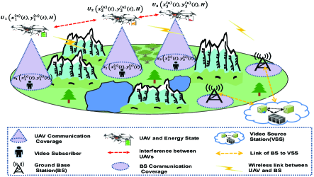
This paper considers an application scenario for providing high-quality video streaming services for a number of ground subscribers by deploying a multi-UAV network, as shown in Fig. 1. In the considered scenario, there is a ground content provider acting as a video source station (VSS), several ground BSs, a multi-UAV network consisting of flying UAVs, the set of which is denoted by , and subscribers, the set of which is . The content provider has the capabilities of video collection, video transcoding, as well as video streaming push and can provide adaptive streaming services for subscribers. In this scenario, we investigate the issue that subscribers cannot directly access the VSS through BSs, mainly because of severe signal blocking. Considering that UAVs can establish LoS links with BSs, we propose to dynamically deploy a multi-UAV network with UAVs acting as flying relays to forward video streams from BSs to subscribers.
To facilitate the mathematical model of the video transmission task, the time domain is discretized into a sequence of time slots, denoted by . As the communication coverage of UAVs is limited, the trajectories of UAVs will be continuously optimized to provide transmission services for subscribers fairly. We denote the time-varying two-dimensional (2D) horizontal coordinate of UAV at time slot by . Denote the location of subscriber at time slot by . All UAVs are deployed at the same altitude, , and the altitudes of all subscribers are negligible compared to . Thus, the distance between UAV and subscriber at time slot can be given by . Considering the stringent QoE requirements of subscribers, it is critical to provide video streaming services via air-to-ground (AtG) LoS links. The reliability and the throughput of non-line-of-sight (NLoS) propagation links cannot be guaranteed for video streaming services. High energy consumption will also be required to compensate for attenuation of NLoS propagation [32, 33]. Besides, according to the research results in [34], the probability of LoS propagation can exceed when the elevation angle between a UAV and a ground subscriber is greater than a threshold , which is related to the propagation environment, such as rural area, urban area, and dense urban. Therefore, the following condition can be held in order to approximate the establishment of a LoS link between a UAV and a ground subscriber.
| (1) |
The channel gain of an AtG LoS link can be calculated by the free-space path loss model[18], where denotes the channel gain from UAV to subscriber at time slot , and respectively represent transmitting and receiving antenna gains, is the speed of light, is the carrier frequency, and is a far-field reference distance. Let , can be rewritten as
| (2) |
Owing to the movement of UAVs and their limited coverage, a subscriber’s serving UAV will be time-varying. We denote the serving UAV selection set at time slot as . For any , indicates that subscriber can select UAV as its serving UAV at time slot ; otherwise, . We assume that at time slot , a subscriber can select at most one UAV as its serving UAV, and a UAV is allowed to deliver video streams to at most one subscriber. Mathematically, we have
| (3) |
As all UAVs share the frequency resource in the considered scenario, a subscriber will receive its intended signal from UAV and interference caused by other UAVs at each time slot. For subscriber , the strength of its received interference can be calculated by where denotes the instantaneous transmit power of UAV at time slot . Then, the signal-to-interference-plus-noise ratio (SINR) experienced by subscriber at time slot can be given by , where is the noise power. According to Shannon’s channel capacity formula, we can calculate the achievable bitrate of subscriber at time slot by
| (4) |
For subscriber , its time-averaged achievable bitrate during the first time slots can be given by .
It is worth noting that the onboard energy of UAVs is limited and needs to be efficiently utilized. In this paper, we mainly consider the communication power consumption of UAVs (exactly, for forwarding video streams) and model the total communication power consumption of UAV at time slot as [32]
| (5) |
where is the onboard circuit power consumption of UAV . The time-averaged transmit power of UAV in the first time slots can be computed by . Accordingly, the time-averaged total communication power consumption of UAV in the first time slots can be written as . The upper-bounded constraints of and can be written as and , where and denote the maximum instantaneous total power consumption and the maximum time-averaged total power consumption of UAV , respectively[35].
2.2 QoE Model
QoE has become an acknowledged performance evaluation standard in video streaming services. The accurate analysis of the key factors influencing QoE will be beneficial for enhancing subscriber satisfaction and improving the utilization of network resources. In the research field of video streaming, high resolution, fluency, low latency, and smoothness of video streaming are four universal factors affecting QoE. These influencing factors, however, are challenging to be optimized simultaneously, especially in a time-varying multi-UAV network. Meanwhile, the dominant influencing factors are diverse for various network services. For example, some applications are sensitive to latency, while others are greatly affected by packet loss ratio. The smoothness of video streaming is closely related to subscribers’ switching strategies towards video streaming of diverse quality and cannot be directly optimized by controlling the multi-UAV network. Considering the time-varying characteristics of the multi-UAV network and the continuous playback requirements of video streaming, we create a novel QoE model incorporating the video bitrate, the latency, and the frame freezing in this paper.
The decoding capabilities and screen sizes of subscriber terminals may be different, and their playback bitrate requirements for the same video streaming may be diverse. In this case, implementing adaptive transmission and playback of video streaming is an effective way of improving QoE. Based on the throughput of the multi-UAV network and the receiving capabilities of subscribers, we design an adaptive video streaming utility model that implements the adaptive matching between subscribers’ required playback bitrates and video bitrates. For a subscriber, its available video bitrate is upper-bounded by its achievable bitrate; otherwise, packet loss or frame freezing will occur. Therefore, the video streaming utility model for all subscribers , which also represents the profit of the multi-UAV network, can be written as
| (8) |
where , represents the required playback bitrate of subscriber , represents the total bandwidth, and , are both positive values that are different for various types of applications.
Latency, especially the startup latency and the rebuffering latency in video streaming, is a crucial factor affecting QoE. The startup latency and the rebuffering latency are closely related to subscribers’ achievable bitrates. The greater the achievable bitrate, the shorter the latency to receive a sufficient amount of video data. Latency is also greatly affected by a subscriber’s selection of serving UAV in the considered application scenario. Hence, the startup and rebuffering latency (briefly, latency) model for any subscriber at time slot is given by
| (9) |
where denotes the duration of a time slot, and is the length of transmitted video data in a time slot. According to (9), we will obtain the latency , when subscriber can select a certain UAV as its serving UAV at time slot ; otherwise, the latency is , namely the interval of one time slot. denotes the total latency of all subscribers at time slot .
The exhaustion of resources in a subscriber’s playback buffer will lead to annoying frame freezing. When the playback bitrate remains unchanged, either the decrease of link throughput or the link interruption can result in the exhaustion of buffer resources. To tackle this issue, it is essential to constrain the time-averaged achievable bitrate by
| (10) |
where, denotes the threshold of time-averaged achievable bitrate of subscriber . In order to meet this constraint, the optimization of UAV trajectories and network resources is desired and should be investigated.
2.3 Problem Formulation
Considering that UAVs are energy-sensitive, our goal is to maximize subscribers’ QoE and minimize the total power consumption of the multi-UAV network. To achieve this goal, we propose to jointly optimize the serving UAV selection , the UAVs’ trajectories , and the UAVs’ transmit power . According to the above analysis, the optimization problem can be mathematically formulated as follows
| (11a) | |||
| (11b) | |||
| (11c) | |||
| (11d) | |||
| (11e) | |||
| (11f) | |||
| (11g) | |||
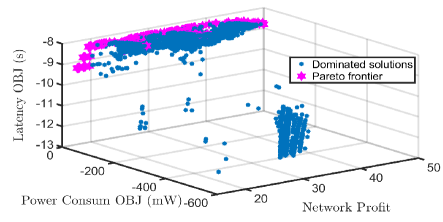
where and are both positive values that reflect the trade-off among the network profit, the total latency, and the total power consumption. One can choose and based on preferences of network operators and subscribers and the Pareto frontier of the formulated multi-objective optimization problem, as depicted in Fig. 2.
The formulated problem is confirmed to be a sequential-decision optimization problem, the solution of which is highly challenging. The video streaming utility model in the objective function is a logarithm function of time-averaged achievable bitrates of subscribers during the first time slots, which not only makes the problem highly time-coupled but also greatly increases the computational complexity of solving the problem. For example, the number of time-varying decision variables of the problem will grow exponentially with the increase of time slot . As a result, to solve this problem directly by exploring some conventional optimization algorithms is unacceptable in terms of computational complexity. Besides, this optimization problem includes the summation term of 2-norm, complex fractional terms, continuous and integer variables, logarithmic-quadratic functions, and non-convex constraints. Thus, the formulated problem is also a mixed-integer non-convex optimization problem that may be NP-hard or even undecidable [37].
To alleviate this highly challenging problem, we first employ the Jensen’s inequality to decouple the time-coupled objective function. Next, considering the advantages of Lyapunov optimization approach in tackling time-averaged problems, we decompose the sequential-decision problem into multiple repeatedly optimization sub-problems at different time slots using the Lyapunov approach. In this way, the curse of dimensionality can be effectively tackled, and the computational complexity of solving the original problem can be greatly reduced. Next, we transform the complex fractional terms into rotated quadratic cones by introducing some slack variables. Finally, alternative and approximate optimization mechanisms with provable performance guarantees are explored to handle the mixed-integer and the non-convex properties of the sub-problems, respectively.
3 Lyapunov-Based Optimization Framework
Observe that there is a logarithmic term of the time-averaged achievable bitrates in the objective function, which significantly hinders the theoretical analysis of the formulated problem. To tackle this issue, we introduce a set of auxiliary variables to transform the logarithmic term. In particular, define an auxiliary vector , let , and , where , we then have . In addition, we define an auxiliary function . By the Jensen’s inequality, the following expression holds, . Based on this inequality, the original problem (11) can be transformed into the following problem.
| (12a) | |||
| (12b) | |||
| (12c) | |||
| (12d) | |||
| (12e) | |||
Remark 1: On one hand, owing to the utilization of Jensen’s inequality, the maximum value of the objective function of (12) is not greater than that of (11). On the other hand, (12a) can obtain the maximum value of (11a) by letting , with being a collection of optimal time-averaged achievable bitrates in (11). Therefore, (12) and (11) are equivalent.
The transformed problem (12), however, is still difficult to be solved due to the existence of time-averaged terms. To this end, the Lyapunov drift-plus-penalty technique is explored to handle the time-averaged terms. We introduce three sets of virtual queues , , , and define
| (13) |
| (14) |
| (15) |
In this way, to enforce the three groups of time-averaged constraints (12b), (12c), and (12d), the following stability requirement should be satisfied.
| (16) |
where .
According to the Lyapunov optimization approach, the Lyapunov function , which is nonnegative and can be regarded as a scalar measure of constraint violation at time slot , is usually defined as the sum of square of all virtual queues. For the convenience of calculation, is defined as .
Correspondingly, the expression of Lyapunov drift-plus-penalty can be written as , where is a Lyapunov drift, is a penalty function, and is a non-negative coefficient, weighing a trade-off between the constraint violation and optimality. Thus, can be chosen properly to ensure that the time average of the penalty function is arbitrarily close to the optimum. According to (13), (14), and (15), we can obtain the following expressions
| (17) |
| (18) |
| (19) |
With (17)-(19) and , the upper bound of the drift-plus-penalty function at time slot can be given by
| (20) |
As a consequence, the minimization of the drift-plus-penalty item can be approximated by minimizing its upper bound, i.e., the right-hand-side (RHS) expression of (20). Then, the optimization problem can be greedily solved by minimizing the upper bound of the drift-plus-penalty function at each time slot. From (20), we can also observe that its RHS expression can be decomposed into three types of independent items, including constant items, auxiliary variable-related items, and resource optimization-related items (exactly, the UAVs’ transmit power , the UAVs’ trajectories , and the serving UAV selection ).
In summary, the Lyapunov-based optimization framework of mitigating (12) can be decomposed into the following repeated optimization sub-problems of a two-layered structure.
-
•
Auxiliary-variable-layer optimization: Optimize (21) to obtain the optimal for .
(21a) (21b) -
•
Resource-layer optimization: The serving UAV selection, the UAVs’ transmit power, and the UAVs’ trajectories will be obtained by solving the following multi-objective optimization sub-problem.
(22a) (22b)
4 Problem solution and Algorithm Design
4.1 Solution to the Auxiliary-Variable-Layer Sub-problem
As the auxiliary function is the total of all individual logarithmic functions, we can then divide this sub-problem into individually optimized sub-problems, each of which can be formulated as
| (23a) | |||
| (23b) | |||
(23a) is a convex function of , and its closed-form solution can be obtained by calculating the derivative. Let , we can obtain
| (24) |
4.2 Solution to the Resource-Layer Sub-problem
It can be observed that (22) includes some logarithmic-quadratic terms and non-convex constraints. It is also a multi-objective optimization problem involving both integer and continuous decision variables. As a result, (22) is difficult to be solved directly. To this end, an iterative optimization scheme is adopted to solve (22) in this paper.
4.2.1 Solution to serving UAV selection sub-problem
Given UAVs’ trajectories and UAVs’ transmit power , the serving UAV selection at time slot can be optimized by solving the following sub-problem.
| (25a) | |||
| (25b) | |||
It can be confirmed that (25) is an integer linear programming problem, and some optimization tools such as MOSEK can be employed to alleviate this sub-problem effectively.
4.2.2 Solution to the UAVs’ transmit power control sub-problem
For any given serving UAV selection , UAVs’ trajectories , and UAVs’ transmit power at the previous time slot , the UAVs’ transmit power can be optimized by solving the following sub-problem.
| (26a) | |||
| (26b) | |||
To simplify the expression of the objective function, we introduce the slack variable , and let . Moreover, we can observe that (26a) includes a latency-related item with being the denominator of the fraction, which greatly hinders the theoretical analysis of (26). To tackle this issue, we introduce the slack variable and let . Specifically, we can transform the latency-related sub-problem in (26a) into the following optimization problem.
| (27a) | |||
| (27b) | |||
| (27c) | |||
| (27d) | |||
According to (4) and (27), the UAVs’ transmit power optimization sub-problem (26) can be reformulated as
| (28a) | |||
| (28b) | |||
| (28c) | |||
The constraint (28b), however, is non-convex, and thus (28) is a non-convex optimization sub-problem. To solve this problem effectively, we need to approximate the non-convex constraint as a convex constraint [38]. The following Proposition presents the approximation results.
Proposition 1.
Given a local point , , one can approximately transform the non-convex constraint (28b) into the following convex one
| (29) |
where, , , and .
Proof.
Please refer to Appendix A. ∎
Based on the relaxation transformation results and the approximation results in Proposition 1, (26) can be approximately transformed into a convex sub-problem. To facilitate the optimization of the approximated convex sub-problem using some convex optimization tools such as MOSEK, we further transform it into a conic problem in the following Lemma.
Lemma 1.
Based on the above approximation results, (26) can be approximately transformed into the following conic problem by introducing a family of auxiliary variables.
| (30a) | |||
| (30b) | |||
| (30c) | |||
| (30d) | |||
Proof.
Please refer to Appendix B. ∎
4.2.3 Solution to the UAV trajectory optimization sub-problem
Given serving UAV selection , UAVs’ transmit power , and UAVs’ trajectories at the previous time slot , the UAVs’ trajectories can be optimized by mitigating the following problem
| (31a) | |||
| (31b) | |||
Similar to the derivation in subsection 4.2.2, after introducing the slack variables and , the optimization problem (31) can be reformulated as
| (32a) | |||
| (32b) | |||
| (32c) | |||
(32) is not convex due to the existence of non-convex constraints (6) and (32b). Therefore, it is quite difficult to obtain its optimal solution.
For constraint (6), it is non-convex. Similar to the analysis and derivation in Proposition 1, the first-order Taylor expansion can be performed to calculate the lower bound of its left-hand-side (LHS) term.
| (33) |
where and denote the 2D horizontal location of the -th and -th UAV at the -iteration of the approximation method explored in Proposition 1, respectively.
For the non-convex constraint (32b), it is much more complex than (6). The following Proposition presents its approximated constraints.
Proposition 2.
Given a local point , , by introducing a slack variable , we can approximately transform the non-convex constraint (32b) into the following convex constraints
| (34) |
| (35) |
where , , and .
Proof.
Please refer to Appendix C. ∎
Based on the above derivation, we can approximately transform the non-convex UAV trajectory optimization sub-problem (31) into a convex one. We further transform the approximate sub-problem into a conic problem in the following Lemma, which can be effectively solved by calling MOSEK.
Lemma 2.
Based on the above approximation results, (31) can be approximately transformed into the following conic problem by introducing a family of slack variables.
| (36a) | |||
| (36b) | |||
| (36c) | |||
| (36d) | |||
| (36e) | |||
Proof.
Please refer to Appendix D. ∎
4.3 Algorithm Design
Based on the above theoretical analysis and derivation, we can summarize the main steps of solving (22) in the following algorithm. Besides, the following Lemma presents the convergence of the algorithm.
Lemma 3.
The iterative optimization Algorithm 1 is convergent.
Proof.
Please refer to Appendix E. ∎
Recall that (11) can be decomposed into two repeated optimization sub-problems. We obtained the closed-form solution of the auxiliary-variable-layer sub-problem. The resource-layer sub-problem can be solved by calling Algorithm 1. We can then summarize the steps of solving (11) in Algorithm 2.
The computational complexity of Algorithm 2 has two main contributors at each time slot, i.e., the auxiliary-variable-layer optimization and the resource-layer optimization. The computational complexity of solving the auxiliary-variable-layer optimization sub-problem is . For the resource-layer optimization, it can be further decomposed into three sub-problems, including serving UAV selection optimization, UAV transmit power optimization, and UAV trajectory optimization sub-problems. The computational complexity of solving the linear integer serving UAV selection optimization sub-problem by a branch-and-bound method is . Both UAV transmit power optimization and trajectory optimization sub-problems are approximately transformed into convex programming; thus, the computational complexities of solving the approximate UAV transmit power optimization and trajectory optimization sub-problems by an interior method are and , respectively [39]. Besides, an iterative optimization scheme is explored to solve the resource-layer optimization sub-problem, and hence, the computational complexity of solving the resource-layer optimization sub-problem is in the worst-case.
5 Simulation and Result Analysis
5.1 Comparison Algorithms and Parameter Setting
In this section, we conduct simulations to verify the effectiveness of the proposed algorithm, and compare it with the following five benchmark algorithms: 1) Nearest Neighbor ASsociation (NNAS) algorithm: It implements the UAV trajectory and transmit power optimization method in [18]. Meanwhile, each UAV only establishes a communication link (if available) with its nearest ground subscriber in the NNAS algorithm. 2) Stationary UAV DEployment (SUDE) algorithm: UAVs hover steadily over the randomly generated locations, as in [25]. Meanwhile, the serving UAV selection and UAV transmit power are optimized using the schemes designed in the proposed algorithm. 3) Stationary UAV with maximum transmit power (SUMTP) algorithm: In SUMTP, UAVs hover steadily over a random selection of locations and deliver video streams with the maximum transmit power. Besides, it adopts the same serving UAV selection scheme as the proposed algorithm. 4) Circular UAV TRajectory (CUTR) algorithm: As in [29], each UAV flies in a circular trajectory with a speed of two m/s. The distance between any two neighboring UAVs is ( is the number of deployed UAVs) km at the initial time. Besides, CUTR adopts the similar serving UAV selection and UAV transmit power optimization schemes as the proposed algorithm. 5) Circular UAV trajectory with the maximum transmit power (CUMTP) algorithm: The difference between CUMTP and CUT is that CUMTP adopts the scheme of the maximum transmit power.
We consider a mountainous suburb area of size m2, where ground subscribers walk randomly in the area. The radio frequency propagation parameters are: carrier frequency GHz, light speed m/s, noise power dBm, total bandwidth MHz, far field reference distance m, antenna transmitting gains , and antenna receiving gains . The values of parameters related to UAVs are set: the maximum instantaneous total power mW, the maximum time-averaged total power mW, circuit power mW, the minimum safety distance m, the maximum flight distance in one time slot m, elevation angle threshold , and fixed flight altitude m. Several parameters related to video transmission are: the length of transmitted video data in a time slot Mb, a turntable game in [29] is called to set the required playback bitrate of subscriber with bps/Hz, let the minimum time-averaged achievable bitrate , and the duration of a time slot s. More system parameters are listed as below: the video streaming utility model parameters and ; , , , , and the maximum number of optimization iteration .
5.2 Performance Evaluation
In this subsection, we design extensive simulations to comprehensively verify the performance of the proposed algorithm, including the stability verification, the QoE performance, and the energy efficiency of the algorithm. To weaken the impact of randomly initialized parameters (e.g., UAV transmit power and locations) on the performance of algorithms, we run all algorithms for ten times, and then their average values are compared.
5.2.1 Results of stability and UAVs’ trajectories
In this simulation, we test the stability of proposed algorithm. The stability refers to the stability of the introduced virtual queues and is defined as , , and .
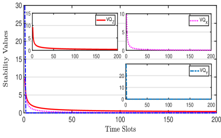
In Fig. 3, we plot the stability trends of the introduced virtual queues. From this figure it can be observed that the obtained stability values of virtual queues are upper bounded over the whole period and tend to zero as time slot increases. According to the definition of mean-rate stability, we can say that the virtual queues are mean-rate stable, and then the time average-related constraint (16) can be satisfied. It also indicates that the frame freezing can be alleviated.
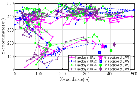
Further, Fig. 4 shows the trajectories of four UAVs in the first 100 time slots and their final positions.
5.2.2 Results of QoE
The QoE performance of the proposed algorithm is verified by comparing it with other five benchmarks. As the frame freezing constraint will not be violated, we mathematically define the QoE as in this simulation, where the network profit and represents the total latency. Recall the definition of the objective function, the latency experienced by an unassociated subscriber in a time slot is , the total latency can then be calculated by .
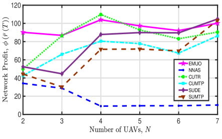
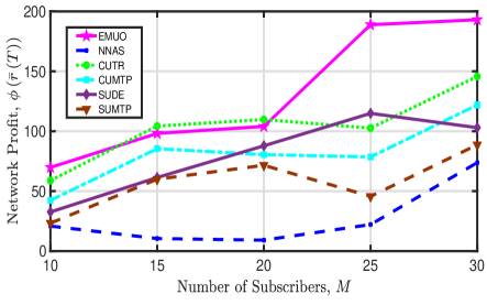
Network Profit: In Fig. 5, we plot the tendency of the achieved network profit versus the number of UAVs and the number of subscribers. From this figure we have the following observations: 1) The proposed EMUO algorithm achieves a high network profit, and it is hard to conclude the tendency of the achieved network profit when varying the number of UAVs. On one hand, more UAVs indicate that more subscribers can simultaneously receive video streams, and then greater network profit might be achieved. On the other hand, the signal interference becomes stronger and the corresponding achievable bitrate of each subscriber is reduced when increasing the number of UAVs; thus, a smaller network profit might also be obtained. Mainly owing to the joint trajectory optimization and power optimization, EMUO achieves greater network profit with the increase of the number of subscribers. 2) For NNAS, it is unable to provide services for subscribers fairly and achieves the smallest network profit. Further, its achieved network profit decreases with an increasing number of UAVs due to stronger signal interference. Yet, NNAS has the potential to achieve higher profit when there are more subscribers in the considered area. 3) For CUTR, its obtained network profit will increase with when . Nevertheless, when , strong signal interference leads to the decrease in the achievable bitrates of subscribers and thus reduces the profit. Diverse from CUTR, CUMTP utilizes the maximum transmit power to deliver video streams. However, constrained by the LoS propagation condition, the coverage range of a UAV cannot be extended by choosing the maximum transmit power. Meanwhile, CUMTP will cause strong signal interference, and thus low network profit is obtained. 4) Similar to the two circular UAV trajectory-based algorithms, SUDE achieves higher network profit than SUMTP. The comparison results indicate that maximizing the transmit power of UAVs cannot effectively increase the network profit, and it is essential to optimize the UAV transmit power.
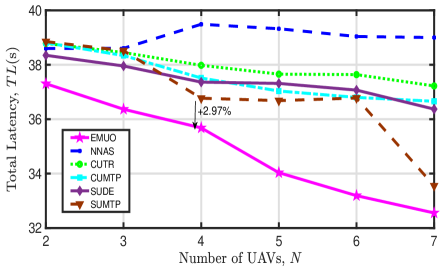
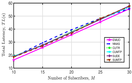
Total latency: The tendency of the total latency of all subscribers versus various numbers of UAVs is illustrated in Fig. 6. From this figure we can observe that: 1) The proposed EMUO algorithm achieves the lowest total latency. 2) For all comparison algorithms except NNAS, more UAVs will lead to the reduction in total latency. This is because more subscribers can simultaneously receive video streams in a time slot when deploying more UAVs. For NNAS, it undermines the fairness of video transmission, and many subscribers have to wait for a long time to receive video streams from UAVs. 3) When there are more subscribers, the achieved total latency of all comparison algorithms will increase as subscribers have to wait to be served. 4) The achieved latency of CUTR and SUDE cannot be significantly reduced when increasing the number of UAVs. Although more subscribers can be simultaneously served, signal interference grows stronger and thus achievable bitrates of subscribers decrease. 5) The achieved latency of EMUO can be reduced by at least 2.97% compared with other algorithms. This indicates that the adverse impact of signal interference can be effectively alleviated through joint serving UAV selection optimization, UAV trajectory optimization, and UAV transmit power optimization.
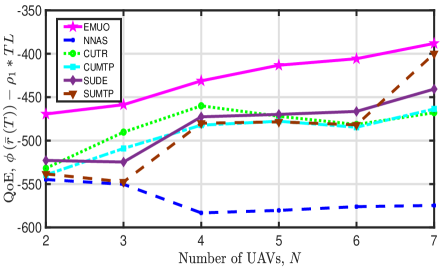
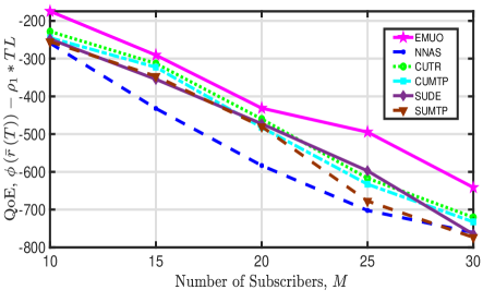
QoE: Besides, we depict the achieved QoE of all comparison algorithms when varying the number of UAVs and subscribers in Fig. 7. The following observations can be obtained from this figure: 1) The proposed EMUO algorithm outperforms the other comparison algorithms and achieves the largest QoE. When increasing the number of UAVs, the achieved QoE of EMUO increases mainly due to the rapid decrease in the total latency. 2) For NNAS, as it obtains the smallest network profit and higher latency, its achieved QoE is the smallest. The large performance difference between NNAS and EMUO verifies the significance of performing serving UAV selection optimization. 3) The obtained QoE of SUDE and SUMTP decrease with an increasing number of subscribers mainly due to the rapid increase in the generated latency. Additionally, for the two stationary UAV-based algorithms, UAVs are randomly and uniformly deployed and hover over the considered area. In this case, although the deployment locations of UAVs remain unchanged, more subscribers can be covered and served when the number of UAVs increases; and thus, higher QoE is obtained. 4) The obtained QoE of both CUTR and CUMTP decrease with an increasing number of subscribers. For CUTR, its achieved QoE, however, shows an oscillation caused by special UAV trajectories and irregular signal interference when increasing the number of UAVs. Besides, when the number of UAVs exceeds four, the obtained QoE of CUMTP cannot be effectively improved. Recalling the results in Fig. 5(a), we can say that circular UAV trajectory-based algorithms cannot obtain high and stable QoE when the number of UAVs is large.
5.2.3 Results of energy efficiency
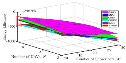
Similarly, we compare the proposed algorithm with all other comparison algorithms to evaluate its performance in terms of energy efficiency, which is defined as , where represents the total power consumption of all UAVs.
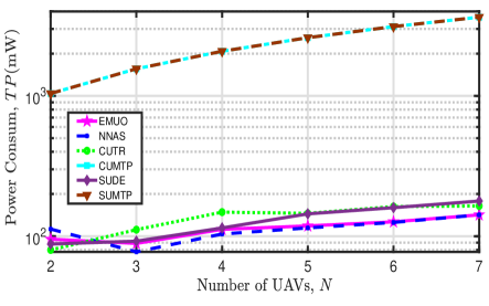
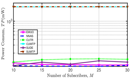
First, we plot the total power consumption of the multi-UAV network by implementing different algorithms in Fig. 8. The following observations can be obtained from this figure: 1) The two maximum-power-based algorithms, i.e., CUMTP and SUMTP, will consume the largest total power. 2) When , the power consumption of all comparison algorithms will increase with an increasing number of UAVs as each UAV will consume circuit and transmit power to serve subscribers. 3) Both signal interference and channel fading will affect the transmit power consumption. When , NNAS consumes the lowest transmit power. This fact indicates that power consumption due to anti-channel fading dominates the transmit power consumption. From the perspective of optimizing power consumption, the above fact further justifies the necessity of enabling LoS propagation for video transmission. 4) The total power consumption of the two trajectory-optimized algorithms, i.e., EMUO and NNAS, decrease with an increasing when . This is because the increase in the number of subscribers leads to the reduction in the distances among UAVs and subscribers and then the weakening of channel fading. When there are more subscribers (e.g., ), NNAS suggests to transmit videos using great power to improve subscribers’ achievable bitrates and reduce latency, as shown in Fig. 6(b).
Second, the influence of the number of UAVs and the number of subscribers on the achieved energy efficiency of all comparison algorithms is depicted in Fig. 9. From this figure, we can have the following observations: 1) Given any UAV number, the energy efficiency achieved by all comparison algorithms decrease with an increasing number of subscribers mainly owing to the rapid reduction in their achieved QoE. 2) When the number of UAVs equals two and the number of subscribers is fifteen, the achieved energy efficiency of EMUO is slightly smaller than that of CUTR. 3) Except for the above case, EMUO is the most energy-efficient algorithm. For instance, the energy efficiency of the multi-UAV network can be improved by up to by running EMUO. 4) Except for the two maximum-power-based algorithms, NNAS obtains the smallest energy efficiency. It is interesting to observe that CUTR is energy-efficient than SUDE when and , and the performance of the two comparison algorithms is reversed when and . In this case, its achieved energy efficiency can be greater than that of the proposed EMUO. Therefore, the above results recommend the following UAV trajectory design scheme: considering the simple UAV movement control, it may be a good choice to deploy UAVs with circular trajectories when the number of UAVs is small and subscribers are sparsely distributed in the considered area.
5.2.4 Results of fairness
Finally, we verify the fairness of the proposed algorithm by comparing all algorithms. To this end, the popular Jain’s fairness index is taken as the evaluation indicator, which can be calculated by .
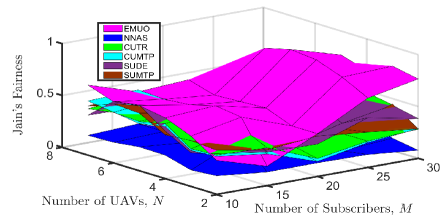
The achieved fairness indexes of all comparison algorithms when varying the number of UAVs and the number of subscribers are shown in Fig. 10. The following observations can be obtained from this figure: 1) Compared with other algorithms, the multi-UAV network can provide fairer video transmission services for subscribers by running EMUO when and . When and , EMUO is overwhelmed by CUTR regarding service fairness. 2) As explained above, the option of maximizing the UAV transmit power will not result in higher service fairness. 3) Likewise, the achieved Jain’s fairness index of CUTR is larger than that of SUDE when and , and SUDE can achieve a higher fairness value than CUTR when and . 4) NNAS undermines the fairness brought by the UAV trajectory optimization and obtains the smallest fairness value.
In summary, when there are few UAVs and subscribers are sparsely distributed, deploying UAVs with circular trajectories can be an acceptable proposal to achieve energy-efficient video transmission. On the contrary, when there are more UAVs or subscribers, a joint UAV trajectory, transmit power, and serving UAV selection optimization scheme for video transmission will be more energy-efficient.
6 Conclusion
In this paper, we investigated the issue of energy-efficient multi-UAV network optimization for subscribers’ QoE-driven video transmission. In particular, considering the time-varying characteristic of the multi-UAV network and the differentiated requirements of subscribers, we first designed a novel QoE model simultaneously considering the video bitrate, the latency, and the frame freezing. Next, we formulated the UAV video transmission problem as a sequential-decision problem to maximize the QoE of subscribers and minimize the total power consumption of the multi-UAV network through the joint optimization and control of UAV transmit power, serving UAV selection, and UAV trajectories. Further, we developed an energy-efficient multi-UAV network optimization algorithm with provable performance guarantees to solve the challenging problem by introducing the key ideas of Lyapunov optimization, iterative optimization, and Taylor expansions. Finally, extensive simulation results showed that the proposed algorithm can effectively improve the QoE of subscribers and is 66.75% more energy-efficient than benchmarks. Although we create a QoE model incorporating the video bitrate, the latency, and the frame freezing, the modeling of subscriber’s playback buffer state is not investigated in this paper. How to integrate the buffer state into the QoE model is challenging and deserves further research in the near future.
References
- [1] K. Wu, P. Yang, X. Cao, and Z. Yu, “QoE-driven UAV video transmission in a multi-UAV network,” in The 12th IEEE/CIC International Conference on Communications in China (ICCC 2023), Dalian, China, August 10-12, 2023. IEEE/CIC, 2023, pp. 1–6.
- [2] G. Geraci, A. García-Rodríguez, M. M. Azari, A. Lozano, M. Mezzavilla, S. Chatzinotas, Y. Chen, S. Rangan, and M. D. Renzo, “What will the future of UAV cellular communications be? A flight from 5G to 6G,” IEEE Commun. Surv. Tutorials, vol. 24, no. 3, pp. 1304–1335, 2022.
- [3] A. Baltaci, E. Dinc, M. Ozger, A. Alabbasi, C. Cavdar, and D. Schupke, “A survey of wireless networks for future aerial communications (FACOM),” IEEE Commun. Surv. Tutorials, vol. 23, no. 4, pp. 2833–2884, 2021.
- [4] V. Hassija, V. Chamola, A. Agrawal, A. Goyal, N. C. Luong, D. Niyato, F. R. Yu, and M. Guizani, “Fast, reliable, and secure drone communication: A comprehensive survey,” IEEE Commun. Surv. Tutorials, vol. 23, no. 4, pp. 2802–2832, 2021.
- [5] X. Cao, P. Yang, M. Alzenad, X. Xi, D. Wu, and H. Yanikomeroglu, “Airborne communication networks: A survey,” IEEE Journal on Selected Areas in Communications, vol. 36, no. 9, pp. 1907–1926, 2018.
- [6] Z. Chang, H. Deng, L. You, G. Min, S. Garg, and G. Kaddoum, “Trajectory design and resource allocation for multi-UAV networks: Deep reinforcement learning approaches,” IEEE Trans. Netw. Sci. Eng., 2022, in Press. DOI: 10.1109/TNSE.2022.3171600.
- [7] M. K. Shehzad, A. Ahmad, S. A. Hassan, and H. Jung, “Backhaul-aware intelligent positioning of UAVs and association of terrestrial base stations for fronthaul connectivity,” IEEE Trans. Netw. Sci. Eng., vol. 8, no. 4, pp. 2742–2755, 2021.
- [8] J. Xu, K. Ota, and M. Dong, “Big data on the fly: UAV-mounted mobile edge computing for disaster management,” IEEE Trans. Netw. Sci. Eng., vol. 7, no. 4, pp. 2620–2630, 2020.
- [9] F. Tang, Y. Kawamoto, N. Kato, and J. Liu, “Future intelligent and secure vehicular network toward 6G: Machine-learning approaches,” Proc. IEEE, vol. 108, no. 2, pp. 292–307, 2020.
- [10] Y. Jiang, Y. Ma, J. Liu, L. Hu, M. Chen, and I. Humar, “MER-wearnet: Medical-emergency response wearable networking powered by UAV-assisted computing offloading and WPT,” IEEE Trans. Netw. Sci. Eng., vol. 9, no. 1, pp. 299–309, 2022.
- [11] T. Cai, Z. Yang, Y. Chen, W. Chen, Z. Zheng, Y. Yu, and H. Dai, “Cooperative data sensing and computation offloading in UAV-assisted crowdsensing with multi-agent deep reinforcement learning,” IEEE Trans. Netw. Sci. Eng., vol. 9, no. 5, pp. 3197–3211, 2022.
- [12] J. Wang, C. Jin, Q. Tang, N. N. Xiong, and G. Srivastava, “Intelligent ubiquitous network accessibility for wireless-powered MEC in UAV-assisted B5G,” IEEE Trans. Netw. Sci. Eng., vol. 8, no. 4, pp. 2801–2813, 2021.
- [13] H. Shimada, Y. Kawamoto, and N. Kato, “Novel computation and communication resources allocation using relay communications in UAV-mounted cloudlet systems,” IEEE Trans. Netw. Sci. Eng., vol. 8, no. 4, pp. 3140–3151, 2021.
- [14] A. Hanyu, Y. Kawamoto, and N. Kato, “Adaptive channel selection and transmission timing control for simultaneous receiving and sending in relay-based UAV network,” IEEE Trans. Netw. Sci. Eng., vol. 7, no. 4, pp. 2840–2849, 2020.
- [15] J. Liu, X. Zhao, P. Qin, S. Geng, and S. Meng, “Joint dynamic task offloading and resource scheduling for WPT enabled space-air-ground power Internet of Things,” IEEE Trans. Netw. Sci. Eng., vol. 9, no. 2, pp. 660–677, 2022.
- [16] M. Nikooroo and Z. Becvar, “Optimization of total power consumed by flying base station serving mobile users,” IEEE Trans. Netw. Sci. Eng., vol. 9, no. 4, pp. 2815–2832, 2022.
- [17] L. A. binti Burhanuddin, X. Liu, Y. Deng, U. Challita, and A. Zahemszky, “QoE optimization for live video streaming in UAV-to-UAV communications via deep reinforcement learning,” IEEE Trans. Veh. Technol., vol. 71, no. 5, pp. 5358–5370, 2022.
- [18] C. Zhan, H. Hu, X. Sui, Z. Liu, J. Wang, and H. Wang, “Joint resource allocation and 3D aerial trajectory design for video streaming in UAV communication systems,” IEEE Trans. Circuits Syst. Video Technol., vol. 31, no. 8, pp. 3227–3241, 2021.
- [19] D. Rosário, J. A. Filho, D. do Rosário, A. Santos, and M. Gerla, “A relay placement mechanism based on UAV mobility for satisfactory video transmissions,” in 16th Annual Mediterranean Ad Hoc Networking Workshop, Med-Hoc-Net 2017, Budva, Montenegro, June 28-30, 2017. IEEE, 2017, pp. 1–8.
- [20] L. Zhu, C. Zhan, and H. Hu, “Transmission rate allocation for reliable video transmission in aerial vehicle networks,” in 14th International Wireless Communications & Mobile Computing Conference, IWCMC 2018, Limassol, Cyprus, June 25-29, 2018. IEEE, 2018, pp. 30–35.
- [21] B. Jiang, J. Yang, H. Xu, H. Song, and G. Zheng, “Multimedia data throughput maximization in Internet-of-Things system based on optimization of cache-enabled UAV,” IEEE Internet Things J., vol. 6, no. 2, pp. 3525–3532, 2019.
- [22] H. Hu, C. Zhan, J. An, and Y. Wen, “Optimization for HTTP adaptive video streaming in UAV-enabled relaying system,” in 2019 IEEE International Conference on Communications, ICC 2019, Shanghai, China, May 20-24, 2019. IEEE, 2019, pp. 1–6.
- [23] X. Tang, X. Huang, and F. Hu, “QoE-driven UAV-enabled pseudo-analog wireless video broadcast: A joint optimization of power and trajectory,” IEEE Trans. Multim., vol. 23, pp. 2398–2412, 2021.
- [24] A. Bera, S. Misra, and C. Chatterjee, “QoE analysis in cache-enabled multi-UAV networks,” IEEE Trans. Veh. Technol., vol. 69, no. 6, pp. 6680–6687, 2020.
- [25] Y. Chen, H. Zhang, and Y. Hu, “Optimal power and bandwidth allocation for multiuser video streaming in UAV relay networks,” IEEE Trans. Veh. Technol., vol. 69, no. 6, pp. 6644–6655, 2020.
- [26] Z. Zhang, Q. Zhang, J. Miao, F. R. Yu, F. Fu, J. Du, and T. Wu, “Energy-efficient secure video streaming in UAV-enabled wireless networks: A safe-DQN approach,” IEEE Trans. Green Commun. Netw., vol. 5, no. 4, pp. 1892–1905, 2021.
- [27] F. Zeng, Z. Hu, Z. Xiao, H. Jiang, S. Zhou, W. Liu, and D. Liu, “Resource allocation and trajectory optimization for QoE provisioning in energy-efficient UAV-enabled wireless networks,” IEEE Trans. Veh. Technol., vol. 69, no. 7, pp. 7634–7647, 2020.
- [28] C. Zhan, H. Hu, S. Mao, and J. Wang, “Energy-efficient trajectory optimization for aerial video surveillance under QoS constraints,” in IEEE INFOCOM 2022 - IEEE Conference on Computer Communications, London, United Kingdom, May 2-5, 2022. IEEE, 2022, pp. 1559–1568.
- [29] P. Yang, K. Guo, X. Xi, T. Q. S. Quek, X. Cao, and C. Liu, “Fresh, fair and energy-efficient content provision in a private and cache-enabled UAV network,” IEEE J. Sel. Top. Signal Process., vol. 16, no. 1, pp. 97–112, 2022.
- [30] Y. Xu, T. Zhang, Y. Liu, D. Yang, L. Xiao, and M. Tao, “Cellular-connected multi-UAV MEC networks: An online stochastic optimization approach,” IEEE Trans. Commun., vol. 70, no. 10, pp. 6630–6647, 2022.
- [31] C. He, Z. Xie, and C. Tian, “A QoE-oriented uplink allocation for multi-UAV video streaming,” Sensors, vol. 19, no. 15, p. 3394, 2019.
- [32] J. Ji, K. Zhu, D. Niyato, and R. Wang, “Joint cache placement, flight trajectory, and transmission power optimization for multi-UAV assisted wireless networks,” IEEE Trans. Wirel. Commun., vol. 19, no. 8, pp. 5389–5403, 2020.
- [33] ——, “Joint trajectory design and resource allocation for secure transmission in cache-enabled UAV-relaying networks with D2D communications,” IEEE Internet Things J., vol. 8, no. 3, pp. 1557–1571, 2021.
- [34] A. Al-Hourani, K. Sithamparanathan, and S. Lardner, “Optimal LAP altitude for maximum coverage,” IEEE Wirel. Commun. Lett., vol. 3, no. 6, pp. 569–572, 2014.
- [35] P. Yang, X. Xi, K. Guo, T. Q. S. Quek, J. Chen, and X. Cao, “Proactive UAV network slicing for URLLC and mobile broadband service multiplexing,” IEEE J. Sel. Areas Commun., vol. 39, no. 10, pp. 3225–3244, 2021.
- [36] Q. Wu, Y. Zeng, and R. Zhang, “Joint trajectory and communication design for multi-UAV enabled wireless networks,” IEEE Trans. Wirel. Commun., vol. 17, no. 3, pp. 2109–2121, 2018.
- [37] P. Belotti, C. Kirches, S. Leyffer, J. T. Linderoth, J. R. Luedtke, and A. Mahajan, “Mixed-integer nonlinear optimization,” Acta Numer., vol. 22, pp. 1–131, 2013.
- [38] G. Scutari, F. Facchinei, and L. Lampariello, “Parallel and distributed methods for constrained nonconvex optimization-part I: Theory,” IEEE Transactions on Signal Processing, vol. 65, no. 8, pp. 1929–1944, 2017.
- [39] Y. Ye, Interior point algorithms: theory and analysis. Toronto, ON, Canada: Wiley, 2011, vol. 44.
Appendix A Proof of Proposition 1
Firstly, we can rewrite the LHS expression of (28b) as
| (37) |
(37) is the sum of a concave function and a convex function and is non-concave. We then explore a successive convex approximate (SCA) method to handle the non-convexity of the corresponding constraint (28b). The core idea of SCA is to obtain a local approximate solution of a non-convex original problem by iteratively solving a series of convex optimization problems with different initial points. Since these local convex problems have the similar geometric characteristics as the non-convex problem, they can be regarded as the approximation of the non-convex problem at the given local points.
Next, we discuss how to obtain the approximation function of non-concave function. Based on the following assumption, we can obtain the approximation function.
Assumption 1.
A function is assumed to be the approximation function of the non-concave function (), when the following conditions hold [38]
-
•
is continuous in .
-
•
is concave in for all .
-
•
Function value consistency: for all .
-
•
Gradient consistency: for all .
-
•
Lower bound: for all , .
In other words, we can approximate an original function with its lower-bound that has the same first-order behavior at each iteration. This is what the SCA method does.
Based on the principle of SCA method, let , and for any local point , which denotes the transmit power of the -th UAV at the -th iteration when exploring the SCA method, we can obtain the lower bound of by the first-order Taylor expansion, i.e.,
| (38) |
Appendix B Proof of Lemma 1
Without loss of generality, we assume that the video access service of subscriber is relayed by a UAV, (29) can then be simplified as
| (39) |
Considering that is a complex logarithmic function, we then introduce a family of auxiliary variables to transform (39) into convex cones. In particular, (39) can be rewritten as
| (40) |
To simplify this expression, we introduce three auxiliary variables , , (), and let
| (41a) | |||
| (41b) | |||
| (41c) | |||
It turns out that (41a)-(41c) are linear constraints. According to the standard form of an exponential cone , (40) can take a different form
| (42) |
Similarly, we can rewrite (27b) into the following expression of a standard rotated quadratic cone
| (43) |
where, .
Appendix C Proof of Proposition 2
However, (44) is not a convex constraint w.r.t . Fortunately, is concave w.r.t . Therefore, a slack variable , can be introduced to alleviate the problem. The LHS expression of (44) can be rewritten as
| (45) |
Observe that the above expression is a sum of a convex function and a concave function. To tackle the non-convex constraint, we explore the SCA method. Let . For any given local point , which denotes the 2D horizontal location of the -th UAV at the -th iteration of the SCA method, we can obtain the lower bound of via conducting the first-order Taylor expansion, i.e.,
| (46) |
Additionally, for the introduced non-convex inequality , we can calculate the lower bound of its RHS term by
| (47) |
Appendix D Proof of Lemma 2
In this appendix, we discuss how to transform some complex constraints into standard convex cones by introducing some slack variables and prove the equivalence of the transformation. For the complex constraint (34), we introduce a variable to slack the Euclidean norm in it and let
| (48) |
By referring to the similar proof in Appendix B, (48) can be rewritten as the following rotated quadratic cone constraint.
| (49) |
Next, we should prove the equivalence of exploring the slack variable scheme. In particular, we should prove that (34) is equivalent to (48) and (50).
| (50) |
For (34), if the constraint (48) is active, it is not hard to know that the feasible regions generated by (48) and (50) are the same as (34). On the contrary, when (31) is optimized under the constraints of (48) and (50), if there is a UAV or a subscriber such that (48) is non-active, we can always decrease towards without changing the value of (31a) and violating (50). Therefore, (34) is equivalent to (48) and (50).
Considering that the term in (34) consists of a complex logarithmic function, we introduce a slack variable to handle it and let
| (51) |
Further, by introducing the variables and and letting their exponential functions and , we can rewrite (51) as the following constraint
| (52) |
As the following equivalent transformation holds,
| (53) |
we can transform (52) into the following set of convex constraints
| (54a) | |||
| (54d) | |||
Similarly, by introducing the slack variable and letting
| (55) |
we can obtain the following exponential cone constraint
| (56) |
Similar, the equivalence of introducing the slack variable can be guaranteed.
Finally, with (48) and (51), the complex (34) can be transformed into the following linear constraint.
| (57) |
Besides, by referring to the standard expression of a quadratic cone, we can rewrite (1) as
| (59) |
where, is a quadratic cone of .
Likewise, (7) can be rewritten as the following quadratic cone constraint
| (60) |
Appendix E Proof of Lemma 3
Given a local point (, , ) at the -th iteration, and denote the corresponding value of (22a) at this point as . By solving (25) we can obtain a solution such that . Given the local point (, , ), we can obtain an updated solution by optimizing (30) and have . Similarly, given the updated local point (, , ), we can obtain a new local point (, , ) by optimizing (36) at the -th iteration and have . To this end, we can conclude that . Further, it can be confirmed that (22a) is low-bounded. Therefore, the iterative optimization Algorithm 1 is convergent. This completes the proof.