Put the Bear on the Chair! Intelligent Robot Interaction
with Previously Unseen Chairs via Robot Imagination
Abstract
In this paper, we study the problem of autonomously seating a teddy bear on a previously unseen chair. To achieve this goal, we present a novel method for robots to imagine the sitting pose of the bear by physically simulating a virtual humanoid agent sitting on the chair. We also develop a robotic system which leverages motion planning to plan SE(2) motions for a humanoid robot to walk to the chair and whole-body motions to put the bear on it. Furthermore, to cope with cases where the chair is not in an accessible pose for placing the bear, a human assistance module is introduced for a human to follow language instructions given by the robot to rotate the chair and help make the chair accessible. We implement our method with a robot arm and a humanoid robot. We calibrate the proposed system with 3 chairs and test on 12 previously unseen chairs in both accessible and inaccessible poses extensively. Results show that our method enables the robot to autonomously seat the teddy bear on the 12 previously unseen chairs with a very high success rate. The human assistance module is also shown to be very effective in changing the accessibility of the chair. Video demos and more details are available at https://chirikjianlab.github.io/putbearonchair/.
I INTRODUCTION
Object affordances describe potential interactions with an object [1]. They are related to the object functionality. For example, a chair is able to afford the functionality of sitting. Thus, it possesses the sitting affordance. For robots operating in unstructured environments and interacting with previously unseen objects, e.g., personal robots, the understanding of object affordances is very desirable [2]. It allows robots to understand how to interact with them efficiently and intelligently. Reasoning about object affordances can also help robots discover the potential of an object to afford a functionality, despite it not being a typical instance of the object class to which the functionality is related (e.g., the improvised chair assembled with books and boxes in Fig. 5(d)). Independently identifying affordances represents a higher level of robot intelligence.
To address the problem of affordance reasoning, we introduced the interaction-based definition (IBD) which defines objects from the perspective of interactions instead of appearances in our previous work [3]. In particular, IBD defines a chair as “an object which can be stably placed on a flat horizontal surface in such a way that a typical human is able to sit (to adopt or rest in a posture in which the body is supported on the buttocks and thighs and the torso is more or less upright) on it stably above the ground”.
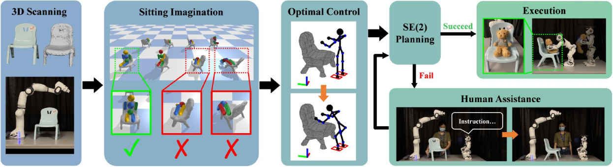
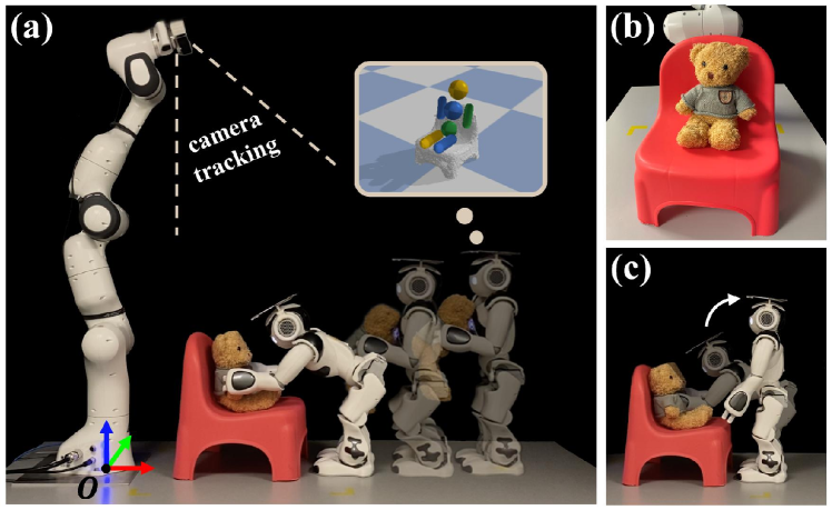
In this paper, we go beyond our previous work. We propose a novel method for robots to imagine how to sit on a previously unseen chair, i.e., the sitting pose for the chair. We develop a robotic system, with a Franka Emika Panda robot arm and a NAO humanoid robot, to actualize the understanding of the sitting affordance by autonomously seating a teddy bear on the chair (Fig. 1). To “put the bear on the chair”, the robot needs to carry the bear to the chair and seat the bear on it. To accomplish this task, the robot first needs to understand the sitting affordance of the chair, i.e., how the chair can be sat. Also, the robot needs to plan a whole-body motion to seat the bear on the chair. Moreover, if the chair is in an inaccessible pose (e.g., when the chair is facing a wall), the robot should be able to reason the accessibility and understand how to make it accessible. In this paper, we introduce a simple but efficient human assistance module with closed-loop visual feedback to enable the robot to instruct a human to rotate the chair and make it accessible for seating the bear. Fig. 2 shows the pipeline of our method. Results show that our method enables the robot to autonomously seat the bear on 12 previously unseen chairs with diverse shapes and appearances in 72 trials, including both accessible and inaccessible chair poses, with a success rate of . Also, our human assistance module is shown to be very effective. It successfully changes the accessibility of the chair for seating the bear with a success rate in 36 trials with inaccessible poses. To our knowledge, this work is the first to physically seat an agent on a previously unseen chair in the real world. The aim of this work is to examine how well the robots are able to accomplish this challenging task by leveraging different components of robotics. We envision promising future applications of our method for robots operating in household environments and interacting with humans.
This work differs from our previous work [3] in various ways. Rather than classifying whether a previously unseen object is a chair or not, in this work, we assume the given object is known as a chair a priori, as such can be determined from [3]. Also, unlike [3] which focuses on perceiving the sitting affordance without real-robot experiments, this work goes beyond by actualizing the understanding of affordances with physical experiments. The main contributions of the paper are as follows:
-
•
A method for robots to imagine the sitting pose for a previously unseen chair.
-
•
A human assistance module to enable the robot to reason about the accessibility of a chair and interact with a human to change the accessibility if necessary.
-
•
A robotic system which is able to autonomously seat a teddy bear on a previously unseen chair for sitting.
II RELATED WORK
Object Affordance of Chairs. The class of chairs is an important object class in human life. The exploration of sitting affordance has become popular in recent decades [4, 5, 6, 3, 7]. Hinkle and Olson [4] simulate dropping spheres onto objects and classify objects into containers, chairs, and tables based on the final configuration of spheres. Grabner et al. [5] fit a humanoid mesh onto an object mesh and exploit the vertex distance and the triangle intersection to evaluate the object affordance as a chair for chair classification. Instead of object classification, we use object affordances to understand the interaction with a chair.
Affordance Reasoning. There is a growing interest in reasoning object affordances in the field of computer vision [8, 9, 10, 11, 12, 13, 14, 2, 15] and robotics [16, 17, 18, 19, 20, 21, 22, 2, 23]. Stoytchev [16] introduces an approach to ground tool affordances via dynamically applying different behaviors from a behavioral repertoire. [17, 18, 9, 10, 14] use convolutional neural networks (CNNs) to detect regions of affordance in an image. Ruiz and Mayol-Cuevas [11] predict affordance candidate locations in environments via the interaction tensor. In contrast to detecting different types of affordances, we focus on understanding the sitting affordance and use it for real robot experiments.
Physics Reasoning. Reasoning of physics has also been introduced to the study of object affordances [3, 19, 24, 25, 26, 27]. Battaglia et al. [24] introduce the concept of an intuitive physics engine which simulates physics to explain human physical perception of the world. Zhu et al. [26] employ physical simulations to infer forces exerted on humans and learn human utilities from videos. The digital twin [28] makes use of physical simulations to optimize operations and predict failures in manufacturing. We do not infer physics or use it to predict outcomes, but exploit physics to imagine interactions with objects to perceive object affordances.
III METHODS
III-A Problem Formulation
Throughout the paper, we assume the given unseen chair is upright and the back of the agent is supported while sitting. The virtual agent in the imagination is an articulated humanoid body (Fig. 3(a)). To seat the agent on the chair, we need to know 1) the sitting pose where and specify the rotation and position of the agent’s base link in the world frame and 2) the joint angles of the agent. However, the real agent is a teddy bear of which the joints have large damping coefficients. The joints can be considered fixed and the joint angles are already close to those of a sitting configuration (Fig. 1(b)). Thus, in this paper, we simplify the problem to just finding .
According to the interaction-based definition (IBD) of chairs (Sec. I), the torso is more or less upright when sitting. Thus, we further simplify the problem by restricting . denotes the rotation about the z-axis of the world frame and is the yaw angle of the base link. denotes the initial rotation which sets the agent to an upright sitting configuration with its face facing towards the x-axis of the world frame. That is, given an unseen chair, the problem becomes finding the position and the yaw angle of the base link in the world frame for sitting. We denote the direction indicated by in the xy-plane as the sitting direction. The base link of the agent is the pelvis link.
III-B Revisit of Sitting Affordance Model (SAM)
In sitting imagination (Sec. III-C), we simulate a virtual humanoid agent sitting on the chair in physical simulations. The resultant configuration of the agent at the end of the simulation is denoted as . The sitting affordance model (SAM) [3] evaluates whether is a correct sitting by comparing it with a key configuration . We briefly review SAM here and further details can be found in [3].
The evaluation is based on four criteria. 1) Joint Angle Score. The joint angles of a configuration can be described with a vector where denotes the total number of the agent’s joints. The joint angle score is defined as . denotes the weight of the -th joints. () is the -th element of (). Lower is better. 2) Link Rotation Score. According to IBD, the torso is more or less upright. Thus, SAM considers the link rotation in the world frame when evaluating . The link rotation score is defined as . is the weight for the -th link. () is the z-axis unit vector of the -th link frame in (). Lower is better. 3) Sitting Height. Sitting height is also an important factor in sitting. SAM takes into account in the evaluation of . 4) Contact. SAM counts the number of contact points of the agent’s links which can be described with a vector where denotes the total number of links.
is classified as a correct sitting if the following are all satisfied: , , , . , , , and are four thresholds. is a binary function which outputs 1 if 1) the total number of contact points is larger than some thresholds and 2) the number of contact points for lower and upper body links are both larger than zeros, and 0 if otherwise.
III-C Sitting Imagination
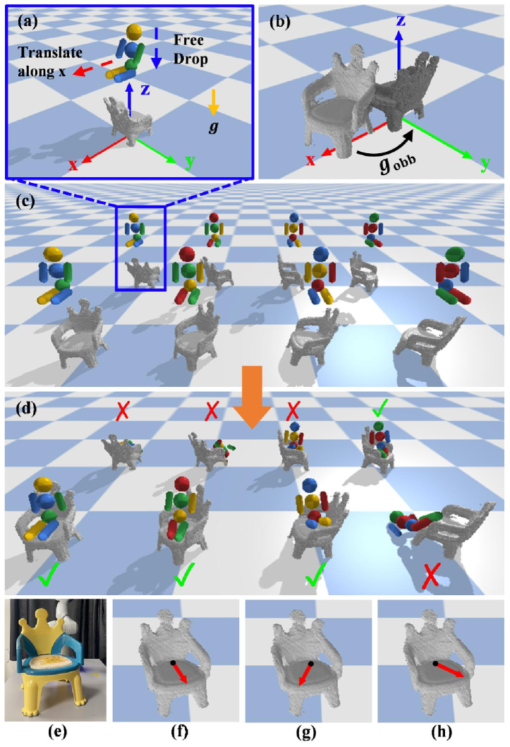
We physically simulate the agent sitting on the chair in different rotations to find and for sitting (Fig. 3). Given the 3D model of the chair, we first compute the minimum volume oriented bounding box (OBB) [29]. As in [3], we then apply a rigid body transformation to the model (Fig. 3(b)). horizontally translates the chair to align the OBB center with the origin of the world frame in the xy-plane. rotates the chair about the z-axis to align the OBB with the coordinate system of the world frame. We apply because we notice that the back of the chair is heuristically coincident with one of the OBB faces which benefits the finding of correct sittings in the imagination. After applying , we attach the world frame as the body frame of the chair.
The rotation of the chair in the simulation is enumerated by setting and (Fig. 3(c)). Note that is a rotation about the z-axis in the world frame. We drop the agent from above the chair to simulate sitting (Fig. 3(d)). Before the drop, the agent is set to a pre-sitting configuration facing the x-axis (Fig. 3(a)). The base link of the agent is placed on a plane 15cm above the chair OBB. For each rotation, we first sample three positions on the plane to drop: the origin and two positions with a translation of along the x-axis from the origin, respectively. is scaled linearly with respect to the size of the OBB. If no more than one correct sitting is found for all rotations, four extra positions are sampled to drop: positions with and translations along the x-axis from the origin, respectively. The reason we start sampling drops close to the origin of the plane, which is aligned with the center of the OBB horizontally, is that most chairs have their seats positioned close to the OBB center. However, the seats for some chairs are closed to the OBB peripheral. Thus, if not enough correct sittings can be found, our search expands towards the peripheral. In total, we simulate 24 drops if no extra drops are needed and 56 drops if otherwise.
The rotation with the largest number of correct sittings is selected as the best rotation for sitting. If more than one rotation has the largest (Fig. 3(f)(g)(h)), we select the one with the smallest averaged value of (lower is better). The sitting pose in the world frame is:
| (1) | |||
| (2) |
where and the inverse ; and are the weighted average of the agent’s position and yaw angle relative to the chair frame of all the correct sittings with the chair rotated by . The weight is the reciprocal value of of the sitting.
III-D Motion Planning
We assume the motion of seating the bear is quasi-static. Due to the complexity of the motion constraints, we formulate the planning of this motion as a trajectory optimization problem [30]:
| (3) | ||||
| subject to | Kinematics constraints | (4) | ||
| Stability constraints | (5) | |||
| Collision constraints | (6) |
where . Kinematics constrains describe the state transition and limit the magnitude of joints and control inputs. Stability constrains confine the horizontal projection of the robot center of mass (COM) to the supporting polygon formed by the feet. Collision constraints ensure that the trajectory is collision-free.
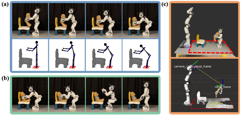
The initial configuration of the robot is a pre-defined standing posture (Fig. 4(a)). The goal configuration is generated via a constrained optimization [30]:
| (7) | ||||
| subject to | Kinematics constraints | (8) | ||
| Stability constraints | (9) | |||
| Collision constraints | (10) |
The cost (Eq. (7)) aims to minimize 1) which is the distance between the COM horizontal projection and the center of the supporting polygon and 2) which is the bending angle of the torso. A less bending torso exerts less torque on the motors, making uprighting the body easier after seating the bear. Kinematics constraints ensure that the bear sits in the imagined sitting pose when the robot is in the goal configuration .
IV SYSTEM PIPELINE
Fig. 2 shows the pipeline of our method. The robot arm first scans and reconstructs the 3D model of the chair (Sec. V-A). The sitting imagination is then conducted to find the imagined sitting pose (Sec. III-C). With , we first determine the goal pose for the NAO to walk to and place the bear. The rotation of is set such that the NAO faces the opposite of the sitting direction indicated by . The position of is on a horizontal ray which originates from the projection of on the xy-plane and points towards the sitting direction. It is initially set such that the NAO is away from . If the NAO is in collision with the chair, we move it along the ray until it is collision-free. After that, if the distance between the NAO and is too large, we move horizontally along the ray and make it closer to the robot due to the robot workspace constraint. We then pre-plan the motion to seat the bear and check the validity of . To reduce the planning time, the motion is simplified as a bilaterally symmetric motion – the motion of the left-half body is symmetric to that of the right-half. The bear is held in hands facing the sitting direction at the beginning of the motion (Fig. 4(a)). We restrict the motion to be an motion, in which only the pitch joints are activated, to maintain the facing of the bear throughout the motion.
The trajectory to walk to is then planned. If is out of the planning arena or blocked by obstacles, no plans will be made. In this case, the NAO gives a language instruction to instruct a human to assist with rotating the chair about the vertical axis such that the sitting direction points towards the NAO where there are no obstacles in between (Fig. 2). The instruction is generated from a template: “Please rotate the chair about the vertical axis for degrees”. . is the multiple of 30 degrees closest to the precise rotation angle such that the sitting direction is pointing towards the NAO. We use multiples of 30 degrees instead of the precise angle because it is easier for humans to understand. The pose of the chair is tracked by iterative closest point (ICP) [34]. The transformation of the chair in the human rotation is denoted as . The imagined sitting pose and the goal are updated and transformed by after the rotation. The robot then tries to plan a trajectory to the updated . This process is repeated until a valid trajectory is found. In practice, we regard the trial as a failure if no trajectories can be found after three rotations. When a valid trajectory is found, the NAO is controlled to walk and follow the waypoints along the trajectory via a PID controller. The walking motion is controlled by the NAOqi SDK111https://developer.softbankrobotics.com/nao6/naoqi-developer-guide/naoqi-apis. The bear is passed to the NAO manually before it starts walking. When the NAO arrives at , a whole-body motion is planned to place the bear based on the robot current pose. Finally, the robot executes the motion, releases the bear, and uprights its body (Fig. 4(b)).
V EXPERIMENTS
Fig. 1(a) shows the experiment setup. A PrimeSense Carmine 1.09 RGB-D camera is mounted on the robot arm. Besides scanning the chair, the camera is also used for tracking the chair and the NAO. The NAO is tracked with an ArUco tag attached on top of its head.
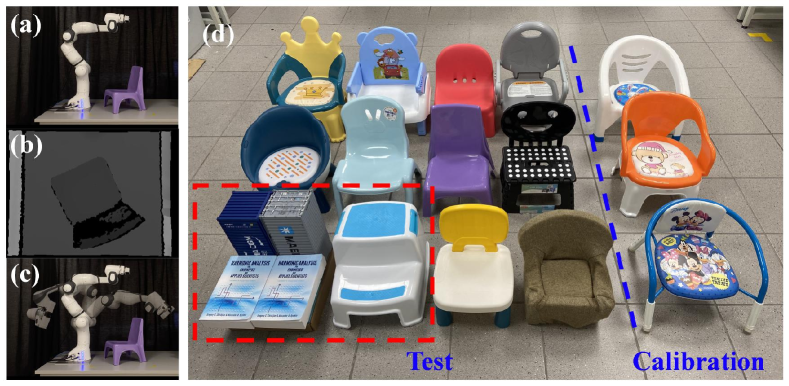
V-A 3D Scanning
In the experiment, the chair is placed randomly in a 5050cm2 squared area in front of the robot arm in its upright pose. The robot arm moves to 9 pre-defined collision-free configurations to capture depth images of the scene (Fig. 5(a)(b)(c)). The pose of the camera at each view is obtained from the forward kinematics of the robot arm. This allows us to use TSDF Fusion [35] to densely reconstruct the scene and the point cloud. The chair is segmented from the scene by plane segmentation in the PCL library [36].
V-B Data
Our dataset contains 15 chairs with diverse shapes and appearances (Fig. 5(d)). They are designed for children aged from 0 to 3. We choose small chairs because the size of the chair is restricted by the workspace of the NAO and the robot arm. If the chair is too tall, the NAO will be too short to put the bear on it; if the chair is too large, the robot arm will not be able to scan it. We use 3 chairs (calibration set) to calibrate the simulation and the motion planning and control. The rest 12 chairs (test set), which are unseen by the robot, are used for testing.
V-C Physical Simulation
Pybullet [37] is used as the physics engine for sitting imagination. The chair and the virtual humanoid agent are imported with the URDF files which specify the mass, COM, inertia matrix, friction coefficient, and joint properties. The collision in the simulation is modelled as inelastic. The physics attributes of the chair is computed with Meshlab [38]. As the chairs in the dataset are designed for children, we set the height and weight of the agent in the simulation accordingly [39].
VI RESULTS & DISCUSSIONS
We implement our method with Robot Operating System (ROS) on a computer running Intel Core i9-10920X @ 3.5GHz CPU. Our unoptimized implementation takes about 70s, 4s, and 29s for 3D scanning and reconstruction, sitting imagination, and motion planning, respectively. The walking and seating motions take about 67s and 24s, respectively.
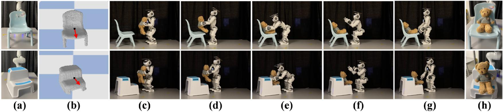
Accessible. In the first set of experiments, the chair is placed such that it is accessible for seating the bear. The sitting direction points towards the NAO with a deviation within a range of degrees. No human assistance is needed in this case. For each chair in the test set, we place it in 3 different poses for testing (36 trials in total) (Fig. 6).
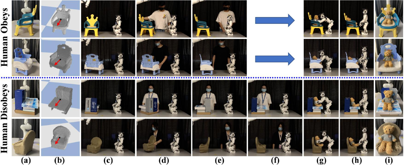
Inaccessible + Human Obeys. In the second set of experiments, the chair is placed such that it is inaccessible. The sitting direction of the chair either points towards 1) the robot arm or 2) to the edges of the planning arena (Fig. 7(a)). In both cases, no valid trajectories can be found in the initial configuration. Human assistance is needed to rotate the chair and make it accessible. We recruit 6 volunteers to participate in the experiments. For each chair in the test set, we place it in 2 different inaccessible poses (24 trials in total). We ask the human to obey the instruction given by the NAO throughout the whole trial (Fig. 7).
Inaccessible + Human Disobeys. There exist many uncertainties in human assistance (e.g., the human is distracted or misunderstands the instruction), resulting in inaccessibility even after a rotation. In this set of experiments, we want to test the robustness of our method in addressing these uncertainties. For each chair in the test set, we place it in an inaccessible pose as in the Inaccessible + Human Obeys setting (12 trials in total). We ask the human to deliberately disobey the first instruction given by the NAO and obey the following instructions (Fig. 7).
We recruit 15 annotators to annotate the experiment results. Each trial is annotated by five different annotators. For each trial, we show the experiment video and the images of the bear at the end of the trial. The annotator is then asked 1) “Do you think the robot has been successful in seating the bear on the chair?” For the trial with human assistance, we also 2) “Is the chair accessible after the human assistance?” The results on the test set are shown in the Tab. I.
| (1) Seating Bear Success | ||||
| Experiment | Trial | Positive Annotation Num. | ||
| Num. | = 5 | 4 | 3 | |
| Accessible | 36 | 26 | 34 | 34 |
| Inaccessible + Human Obeys | 24 | 18 | 22 | 23 |
| Inaccessible + Human Disobeys | 12 | 10 | 10 | 11 |
| Total | 72 | 54 | 66 | 68 |
| (2) Chair Accessible After Human Assistance | ||||
| Experiment | Assist. | Positive Annotation Num. | ||
| Num. | = 5 | 4 | 3 | |
| Inaccessible + Human Obeys | 23 | 23 | 23 | 23 |
| Inaccessible + Human Disobeys | 11 | 10 | 11 | 11 |
| Total | 34 | 33 | 34 | 34 |
In table (1) of Tab. I, we show the number of trials with at least 5, 4, and 3 positive annotations to the first question. We count the trial as successful if the sitting imagination found the sitting pose and more than half of all the 5 annotations (at least 3) are positive. In general, we are able to achieve a very high success rate of on the 12 unseen chairs in the test set (68 out of 72). The step stool accounts for all the 4 failure cases in the 72 trials. The sitting imagination fails to find the sitting pose because the depth of the seat is too small. A successful trial of the step stool is shown in Fig. 6. Remarkably, the success rate of all the 6 trials of the improvised chair is . This opens up a promising potential of our imagination method to discover the affordance of an object which can afford the sitting functionality despite it not being a typical chair.
In table (2), we show the total number of trials with human assistance and the number of trials with at least 5, 4, and 3 positive annotations to the second question. The goal of human assistance is to make the chair accessible for placing the bear. We evaluate the accessibility of the chair at the end of human assistance. We only count the trial in which human assistance is involved, i.e., we disregard the failure trials where the sitting imagination fails to find the sitting pose and no instructions will be given. We consider the chair accessible if more than half of all the annotations are positive. The results show that our human assistance module is very effective – it achieves a success rate in making the chair accessible in all the trials with successful sitting imagination.
VII CONCLUSIONS & FUTURE WORK
We propose a novel method for robots to imagine the sitting pose for a previously unseen chair. We develop a robotic system which is able to seat a teddy bear on the chair autonomously via robot imagination. Moreover, we introduce a module for robots to ask a human to assist with changing the accessibility of the chair when it is in an inaccessible pose. Results show that our method enables the robot to seat the bear on 12 previously unseen chairs in 72 trials with a very high success rate. The human assistance module is also shown to be very effective in making the chair accessible from inaccessible poses. Future work can focus on exploring more versatile whole-body motion planning methods for seating the bear on chairs.
ACKNOWLEDGMENT
The authors thank Yuanfeng Han for discussions, all the volunteers for the human assistance in the experiments, and all the annotators for the human annotations.
References
- [1] J. J. Gibson, The Ecological Approach to Visual Perception. Boston, MA, USA: Houghton Mifflin, 1979.
- [2] L. Bogoni and R. Bajcsy, “Interactive recognition and representation of functionality,” Computer Vision and Image Understanding, vol. 62, no. 2, pp. 194–214, 1995.
- [3] H. Wu, D. Misra, and G. S. Chirikjian, “Is That a Chair? Imagining Affordances Using Simulations of an Articulated Human Body,” in 2020 IEEE International Conference on Robotics and Automation (ICRA), 2020, pp. 7240–7246.
- [4] L. Hinkle and E. Olson, “Predicting object functionality using physical simulations,” in 2013 IEEE/RSJ International Conference on Intelligent Robots and Systems (IROS), 2013, pp. 2784–2790.
- [5] H. Grabner, J. Gall, and L. Van Gool, “What makes a chair a chair?” in Proceedings of the IEEE Conference on Computer Vision and Pattern Recognition (CVPR), 2011, pp. 1529–1536.
- [6] V. Seib, M. Knauf, and D. Paulus, “Detecting Fine-grained Sitting Affordances with Fuzzy Sets.” in Proceedings of the 11th Joint Conference on Computer Vision, Imaging and Computer Graphics Theory and Applications (VISIGRAPP 2016), 2016, pp. 289–298.
- [7] E. Bar-Aviv and E. Rivlin, “Functional 3D Object Classification Using Simulation of Embodied Agent,” in Proceedings of the British Machine Vision Conference (BMVC), 2006, pp. 307–316.
- [8] A. Myers, C. L. Teo, C. Fermüller, and Y. Aloimonos, “Affordance detection of tool parts from geometric features,” in 2015 IEEE International Conference on Robotics and Automation (ICRA), 2015.
- [9] J. Sawatzky, A. Srikantha, and J. Gall, “Weakly Supervised Affordance Detection,” in Proceedings of the IEEE Conference on Computer Vision and Pattern Recognition (CVPR), 2017, pp. 2795–2804.
- [10] A. Roy and S. Todorovic, “A Multi-scale CNN for Affordance Segmentation in RGB Images,” in European Conference on Computer Vision (ECCV). Springer, 2016, pp. 186–201.
- [11] E. Ruiz and W. Mayol-Cuevas, “Geometric Affordance Perception: Leveraging Deep 3d Saliency With the Interaction Tensor,” Frontiers in Neurorobotics, vol. 14, p. 45, 2020.
- [12] Y. Zhu, A. Fathi, and L. Fei-Fei, “Reasoning about Object Affordances in a Knowledge Base Representation,” in European Conference on Computer Vision (ECCV), 2014, pp. 408–424.
- [13] S.-B. Ho, “Representing and using functional definitions for visual recognition,” Ph.D. dissertation, The University of Wisconsin-Madison, 1987.
- [14] C. Desai and D. Ramanan, “Predicting Functional Regions on Objects,” in Proceedings of the IEEE Conference on Computer Vision and Pattern Recognition Workshops, 2013, pp. 968–975.
- [15] A. Bansal, S. S. Rambhatla, A. Shrivastava, and R. Chellappa, “Detecting human-object interactions via functional generalization,” in Proceedings of the AAAI Conference on Artificial Intelligence, vol. 34, no. 07, 2020, pp. 10 460–10 469.
- [16] A. Stoytchev, “Behavior-Grounded Representation of Tool Affordances,” in 2005 IEEE International Conference on Robotics and Automation (ICRA), 2005, pp. 3060–3065.
- [17] T.-T. Do, A. Nguyen, and I. Reid, “AffordanceNet: An End-to-End Deep Learning Approach for Object Affordance Detection,” in 2018 IEEE International Conference on Robotics and Automation (ICRA), 2018, pp. 5882–5889.
- [18] F.-J. Chu, R. Xu, and P. A. Vela, “Learning Affordance Segmentation for real-World Robotic Manipulation via Synthetic Images,” IEEE Robotics and Automation Letters, vol. 4, no. 2, pp. 1140–1147, 2019.
- [19] H. Wu and G. S. Chirikjian, “Can I pour into it? Robot Imagining Open Containability Affordance of Previously Unseen Objects via Physical Simulations,” IEEE Robotics and Automation Letters, vol. 6, no. 1, pp. 271–278, 2020.
- [20] P. Abelha and F. Guerin, “Learning how a tool affords by simulating 3D models from the web,” in 2017 IEEE/RSJ International Conference on Intelligent Robots and Systems (IROS), 2017, pp. 4923–4929.
- [21] L. Piyathilaka and S. Kodagoda, “Affordance-map: Mapping human context in 3D scenes using cost-sensitive SVM and virtual human models,” in 2015 IEEE International Conference on Robotics and Biomimetics (ROBIO), 2015, pp. 2035–2040.
- [22] R. Bajcsy, “Active perception,” Proceedings of the IEEE, vol. 76, no. 8, pp. 966–1005, 1988.
- [23] H. Kjellström, J. Romero, and D. Kragić, “Visual object-action recognition: Inferring object affordances from human demonstration,” Computer Vision and Image Understanding, vol. 115, no. 1, pp. 81–90, 2011.
- [24] P. W. Battaglia, J. B. Hamrick, and J. B. Tenenbaum, “Simulation as an engine of physical scene understanding,” Proceedings of the National Academy of Sciences, vol. 110, no. 45, pp. 18 327–18 332, 2013.
- [25] Y. Zhu, Y. Zhao, and S.-C. Zhu, “Understanding Tools: Task-Oriented Object Modeling, Learning and Recognition,” in Proceedings of the IEEE Conference on Computer Vision and Pattern Recognition (CVPR), 2015.
- [26] Y. Zhu, C. Jiang, Y. Zhao, D. Terzopoulos, and S.-C. Zhu, “Inferring Forces and Learning Human Utilities from Videos,” in Proceedings of the IEEE Conference on Computer Vision and Pattern Recognition (CVPR), 2016, pp. 3823–3833.
- [27] L. Kunze and M. Beetz, “Envisioning the qualitative effects of robot manipulation actions using simulation-based projections,” Artificial Intelligence, vol. 247, pp. 352–380, 2017.
- [28] S. Boschert and R. Rosen, “Digital Twin—The Simulation Aspect,” in Mechatronic Futures, 2016, pp. 59–74.
- [29] M. Dawson-Haggerty et al., “Trimesh,” https://trimsh.org/, 2019–2021.
- [30] Y. Han, R. Li, and G. S. Chirikjian, “Can I lift it? Humanoid robot reasoning about the feasibility of lifting a heavy box with unknown physical properties,” in 2020 IEEE/RSJ International Conference on Intelligent Robots and Systems (IROS), 2020, pp. 3877–3883.
- [31] J. J. Kuffner and S. M. LaValle, “RRT-Connect: An efficient approach to single-query path planning,” in 2000 IEEE International Conference on Robotics and Automation (ICRA), vol. 2, 2000, pp. 995–1001.
- [32] I. A. Şucan, M. Moll, and L. E. Kavraki, “The Open Motion Planning Library,” IEEE Robotics & Automation Magazine, vol. 19, no. 4, pp. 72–82, 2012.
- [33] J. Pan, S. Chitta, and D. Manocha, “FCL: A general purpose library for collision and proximity queries,” in 2012 IEEE International Conference on Robotics and Automation (ICRA), 2012, pp. 3859–3866.
- [34] P. J. Besl and N. McKay, “A method for registration of 3-D shapes,” IEEE Transactions on Pattern Analysis and Machine Intelligence, vol. 14, no. 2, pp. 239–256, 1992.
- [35] B. Curless and M. Levoy, “A Volumetric Method for Building Complex Models from Range Images,” in Proceedings of the 23rd annual conference on Computer graphics and interactive techniques, 1996, pp. 303–312.
- [36] R. B. Rusu and S. Cousins, “3D is here: Point Cloud Library (PCL),” in 2011 IEEE International Conference on Robotics and Automation (ICRA), 2011, pp. 1–4.
- [37] E. Coumans and Y. Bai, “Pybullet, a python module for physics simulation for games, robotics and machine learning,” http://pybullet.org, 2016–2021.
- [38] P. Cignoni, M. Callieri, M. Corsini, M. Dellepiane, F. Ganovelli, and G. Ranzuglia, “Meshlab: an Open-Source Mesh Processing Tool.” in Eurographics Italian Chapter Conference, vol. 2008, 2008, pp. 129–136.
- [39] M. D. Onis, “The WHO child growth standards.” Pediatric nutrition in practice, pp. 254–269, 2008.