Progressive tearing and cutting of soft-bodies in high-performance virtual reality
Abstract.
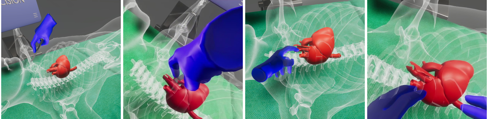
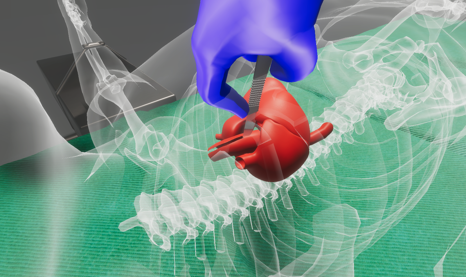
We present an algorithm that allows a user within a virtual environment to perform real-time unconstrained cuts or consecutive tears, i.e., progressive, continuous fractures on a deformable rigged and soft-body mesh model in high-performance 10ms. In order to recreate realistic results for different physically-principled materials such as sponges, hard or soft tissues, we incorporate a novel soft-body deformation, via a particle system layered on-top of a linear-blend skinning model. Our framework allows the simulation of realistic, surgical-grade cuts and continuous tears, especially valuable in the context of medical VR training. In order to achieve high performance in VR, our algorithms are based on Euclidean geometric predicates on the rigged mesh, without requiring any specific model pre-processing. The contribution of this work lies on the fact that current frameworks supporting similar kinds of model tearing, either do not operate in high-performance real-time or only apply to predefined tears. The framework presented allows the user to freely cut or tear a 3D mesh model in a consecutive way, under 10ms, while preserving its soft-body behaviour and/or allowing further animation.
1. Introduction
Since their inception, rigged animated models (Magnenat-thalmann et al., 1988) have become a major research topic in real-time computer graphics. Experts have been experimenting with various animation and deformation techniques, pushing the boundaries of realism and real-time performance. As the industry of Virtual, Augmented Reality (VR, AR) rapidly grows, the term of full user-immersion is being researched extensively. Fully-immersive virtual reality systems mainly aim to enable users to experience and perceive the virtual environments as real (Protopsaltis and Papagiannakis, 2020). To maintain user immersion at all times, these VR systems must produce and project a high number of frames per second, which implies that the computational latency for each frame should be minimal. In this regard, increasingly more complex and optimized algorithms are being developed. Sophisticated computer graphics tools involve the ability to perform cuts, tears and drills on the surface of a skinned model (Bruyns et al., 2002; Kamarianakis and Papagiannakis, 2021). Such algorithms are aiming to increase user immersion and to be used as sub-modules of even more complex operations. However, their scale-up for the extreme real-time conditions of virtual reality environments utilizing mobile, all-in-one un-tethered head-mounted displays (HMDs), remains an active field of research.
The need to interact in a shared virtual environment with other participants in the upcoming metaverse pushes the envelope for more realistic deformation simulations that lead to more complex techniques and interaction paradigms. In the physical world, certain deformable objects, e.g., a soft or hard tissues, are deformed naturally when external forces are applied on them. To preserve immersion and avoid the uncanny valley in VR, the rigid object’s physical behavior needs to be replicated in VR too (Terzopoulos et al., 1987; Macklin et al., 2014; Papagiannakis et al., 2018). One way to accomplish this is via the so-called soft-body mesh deformation (Papagiannakis et al., 2020), a suite of algorithms that essentially dictates how the vertices of a mesh should affect one another when an external force is applied anywhere on the surface of the model.
Performing interactive cuts on a model is not something new; However, most techniques are not suitable for applications requiring high frame-rates as they are based on finite-element methods. Moreover, implemented cuts in such applications are in most cases constrained: camera, model or user degrees of freedom, i.e. the user cannot freely cut anywhere on the model; a set of predefined cuts and their animations are usually produced and placed in the virtual environment by VR designers or artists, and each one is played when triggered by the user’s specific and constrained actions.
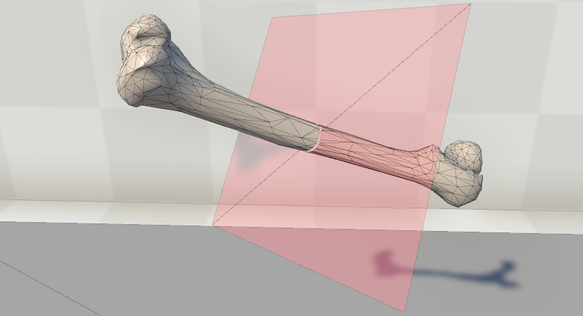
In this work, we propose a framework that allows the user to perform realistic tears, i.e., small cuts, on the surface of a model. Our algorithms are based on pure geometric operations on the surface mesh, and therefore are amenable to yield real-time results in VR, even in low-spec devices such as mobile VR head-mounted displays (HMDs). The significance of our work lies on the fact that in the current state-of-the-art, similar tears on a rigged 3D model in VR are predefined via linear-blend skinning animations, in order to allow them to playback in real-time. Our methods can be implemented in modern game engines such as Unity3D and Unreal Engine; convincing results are illustrated in the video accompanying this work (also, see Fig. 1). The specific calculations must be performed in real-time within a 10-20 ms to preserve user immersion. The ongoing research for increased realism in virtual environments heavily impacts educational and training applications, especially the ones regarding VR medical training (and beyond) (Papagiannakis et al., 2022).
2. Previous Related Work
(Parker and O’Brien, 2009) proposes a simplified version of previous FEM techniques for use in video-games and real-time simulations. They utilize a linearized semi-implicit solver and a well-mastered and optimized parallelized implementation on CPU of the conjugate gradient method. The adopted approach avoids re-meshing, by constraining the fracture on the faces of the simulation elements. It requires the duplication of vertices, while further introduces “splinters” that hide the produced artifacts. The embedded fracture model relies on maximum tensile stress criterion, element splitting according to a fracture plane, and local re-meshing to ensure a conforming mesh. This approach leads to a fast and robust fracture simulation for stiff and soft materials.
(Mitchell et al., 2015) proposed a cutting algorithm, based on (Sifakis et al., 2007), that allows arbitrary cracks and incisions of tetrahedral deformable meshes. In their work, the utilization of low resolution meshes assists the efficient simulation of the model, while preserving the surface detail by embedding a high-resolution material boundary mesh, for rendering and collision handling. The method allows the accurate cutting of high-resolution embedded meshes, arbitrary cutting of existing cuts, and progressive cuttings during object deformation. The utilized algorithm is based the virtual node algorithm, that duplicates elements intersecting with the cutting geometry, rather than splitting them. The extended algorithm allows arbitrarily generalized cutting surfaces at smaller scales than tetrahedron resolution, and improves the shortcoming of the original algorithm, that restricted one cut per face and did not handle degenerate cases. The algorithm is based on embedding cracks in virtual elements, which limits the accuracy of the crack propagation computations. In this work several offline progressive cutting use cases were simulated by the proposed algorithm.
Aiming to model physical object cutting behavior, (He et al., 2022) proposes an algorithm for highly realistic virtual cutting simulation, showing the contact effect before the cutting occurs, that considers deformable objects’ fracture resistance. It utilizes a versatile energy-based cutting fracture evolution model, based on Griffith’s energy. It introduces a tailored cut-incision evolution scheme that constraints the cutting tool’s interaction with the deformable object, by evaluating the stage at which the cutting starts. To allow the surface indentation prior to cutting, the adapted model uses a material-aware scheme to generate the appropriate realistic and consistent behavior of the cutting tool, and the visual indentation deformation of the object. The designed framework is based on the co-rotational linear FEM model to support large deformations of soft objects and also adopt the composite finite element method (CFEM) to balance between simulation accuracy and efficiency. Additionally, it handles the collision and cut incorporation in the same way as the current FEM-based cutting methods using hexahedral elements. The experimental results show that realistic cutting simulations of various deformable objects with various materials and geometrical characteristics that introduce small computational cost for desktop systems.
Li et al. (Li et al., 2021) propose real-time tearing and cutting operations on deformable surfaces using local Cholesky factorization updates in the global pass of a projective dynamics solver. These updates assist the handling of the simulations with topology changes. This adopted approach involves addition of new vertices, topological changes, and re-meshing operations, and allows effective gradual and progressive updates, which is common in real-time physics based simulations.
3. Our Approach
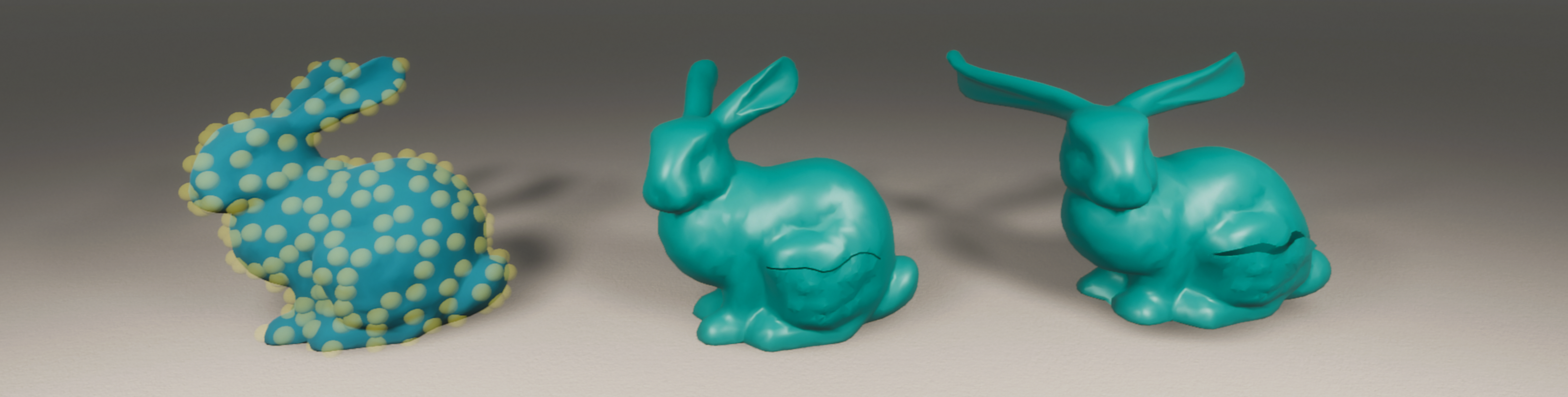
Our methodology is based on the techniques of (Kamarianakis and Papagiannakis, 2021), where the authors describe simple cut and tear operations on a 3D mesh using basic geometric operations. Our optimized tearing module (see Section 3.1) allow for progressive uninterrupted tears i.e., the user can freely perform tears successively similar to a surgeon’s tearing gesture. Furthermore, our cutting module (see Section 3.2) performs straight cuts, producing two (or more) fully deformable sub-meshes. Both modules operate on deformable meshes, using geometric algebra operations. To accomplish the so-called soft-body mesh deformation, we have developed a suitable particle decomposition on the model’s vertices based on (Nealen et al., 2006), where the model’s vertices are clustered into groups, and physics particles are assigned on each group to handle forces and collisions (see Section 3.3). Upon mesh import, the particles are generated as described in Section 3.3.1, thus enabling soft-body behaviour in the original model. The pipeline used to properly simulate this behaviour in a modern game engine is provided in Section 3.3.2. After performing a tear (see Section 3.1) or cut operation (see Section 3.2) on the model, apart from the partial re-meshing that the model undergoes, a subsequent update of the nearby particles, involving affected vertices, is also required (see Section 3.3.3). This crucial step increases the realism of the torn model, as it allows proper visual simulation, such as deforming or animating, of the torn area. Finally, in Section 3.3.4, we propose an optional step towards optimizing the visual outputs of a torn soft-body model.
Via the proposed algorithms, we are able to perform real-time continuous tears on a soft-body model and update the underlying particle decomposition to obtain highly realistic results in VR. Our methods were designed with the lowest possible computational complexity to yield real-time results and high frame-rates in VR. Lastly, proper handling and weight assignment (Kamarianakis and Papagiannakis, 2021) to the tear-generated vertices allow us to tear not only rigid but also skinned models, where in the latter case, further animation is still feasible.
3.1. The Tear Algorithm
In order to achieve real-time tearing results, we have opted for basic geometric primitives, e.g., face-plane intersections and face ray-casting, as basic building blocks for our algorithms. This approach allows for fast identification of the faces affected by the tear.
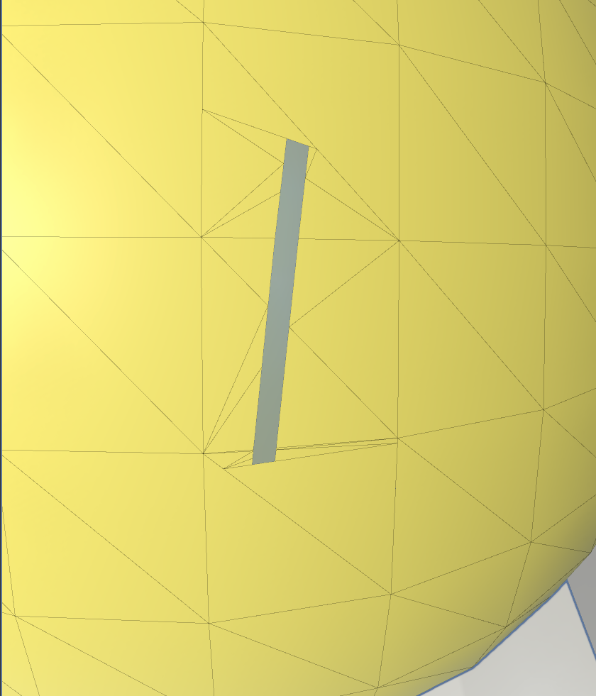
In our implementation, the tear width is user defined. In non-zero settings, a destructive tear takes place: faces that fall in the tear-gap are completely or partially clipped, i.e., removed from the model. Partially clipped faces are calculated by their intersections with the tear-gap surrounding box which is defined by “connecting” consecutive bounding-boxes of single tear segments.
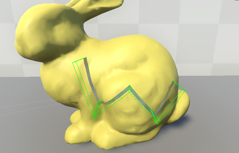
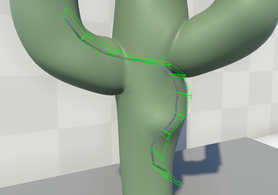
In case of a single tear segment, such a bounding box is aligned and bounded by the scalpel’s endpoints in its final position and the scalpel’s intersection with the model in its initial position; the width of the box is equal to the user defined tear width (see Fig. 5). As the user moves the scalpel, freely tearing the model, several scalpel’s positions are sampled at specific time or distance intervals, defining multiple consecutive tears segments. In case of abrupt movements in the scalpel’s trajectory, the algorithm forces extra sampling on the scalpel’s position. To avoid jagged edges on the tearing path, the algorithm makes sure that consecutive bounding boxes do not overlap, by utilizing non rectangular bounding boxes instead (see Fig. 5).
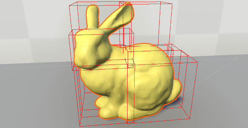
To further optimize the performance of the tear algorithm, the mesh is segmented into smaller groups, called mesh sections. Each mesh section is defined as an axis aligned bounding box and contains groups of the mesh faces. This division of the mesh into smaller sections reduces significantly the Tear algorithm running time, as the affected mesh section is only a small subset of the entire mesh (see Fig. 4). The number and size of these sections are user defined.
Some comments on the steps of the tear algorithm are found below.
-
•
In Line 8, the affected mesh sections are identified and searched for faces to be added to the search list . This reduces running times, especially in complex models with a large number of vertices.
- •
- •
- •
3.2. The Cut Algorithm
The algorithm to perform a thorough straight cut on the mesh model is a simplified version of the respective single tear algorithm. Indeed, we define the cutting plane as the plane that goes through the following three points: the initial intersection point of the model mesh with the scalpel at a time step, and the scalpel’s endpoints after a specific time step; notice that these three points should not be co-linear, otherwise the selected time step is altered.
As in tear algorithm, if the model is a soft-body (see Section 3.3), the particles map is also updated (see Section 3.3.3) during Line 6. After applying the cutting algorithm, each sub-model will lie on the same side of the cutting plane (see Fig 7).
3.3. The Particle System
3.3.1. Generating the Initial Particles
The offline process followed to generate the initial particles is summarized in Algorithm 3.
Some remarks on the particle generation algorithm can be found below
- •
-
•
In terms of modern game engines (e.g., Unity3D), we would describe the particles spawned in Line 4 as a GameObject with a spherical collider and a rigidbody to handle physics forces.
-
•
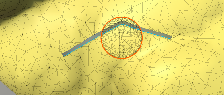
To properly simulate soft-bodies, we apply a typical spring mass approach (Nealen et al., 2006), with some modifications (e.g. the inside pressure is not used to calculate the movement of each particle). In Line 5, each particle gets connected to its anchor point’s position vertex, via a spring, thus ensuring that the particles will always tend to return to their initial anchor position upon displacement. (see Fig. 8)
-
•
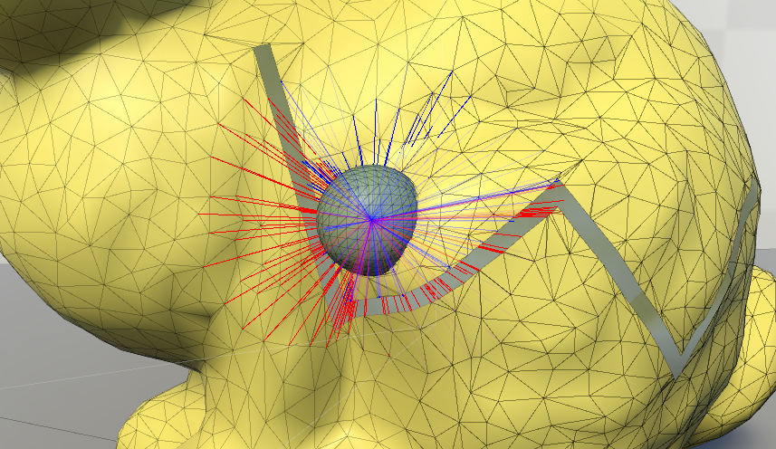
In Line 9, the vertices assigned to the particle are the ones that will be affected by ’s potential displacement, with a weight inversely proportional to their distance from the ’s spawn position, usually based on a sigmoid function.
-
•
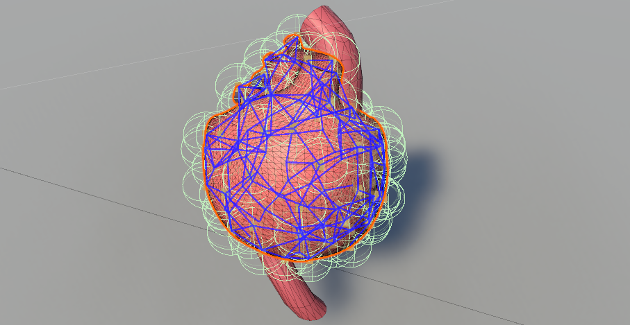
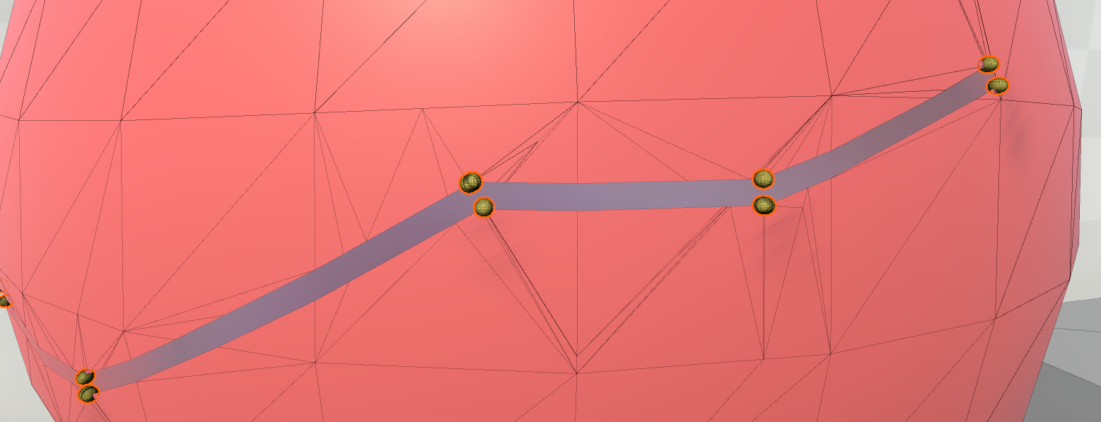
In Line 14 we may determine each particle’s adjacent particle neighbours. This grid of particles (see Fig 9) will eventually act as a set of control points that will enable soft-body deformations; upon moving a particle, all neighbouring particles will also be partially displaced, and the affected vertices will yield the desired effect. A particle’s displacement due to the movement of an adjacent particle is inversely proportional to the distance of their anchor points.
The connections between particles and vertices affected or neighbouring particles, along with the respective influence weights, are referred to as the particle map.
3.3.2. Particle Simulation
The particle simulation is performed almost natively by modern game engines, such as Unity3D, as it involves the same mechanics with joint animation, i.e., both frameworks include control points, and vertices with weights assigned to them.
Particularly, for static meshes, only the particles’ anchor positions need to be updated. In each simulation update, Unity3D automatically calculates forces and collisions, and applies the position changes for each particle, and the corresponding weighted displacement on the assigned vertices. On the other hand, skinned meshes involve additional steps in each simulation update. Initially, the particle’s anchor position is calculated based on the pose of the model at the specific time step. As the anchor points are essentially vertices of the mesh, the animation equation is applied to obtain these positions. Subsequently the particle’s adjacency is updated, by re-applying Line 4 of Section 3.3.1; as the position of anchor points might have been altered, the particles’ adjacent neighbours may have changed, based on the distance threshold. Finally, the same mechanics with a static mesh are applied, i.e., determine the position of the particle and consequently of the affected vertices. Specifically, the final global position of the -th vertex of the model is determined, by evaluating
| (1) |
where
-
•
and are the final and initial homogeneous coordinates of the -th vertex,
-
•
contains the indices of the particles that affect the -th vertex,
-
•
is the corresponding influence factor between the -th particle and the -th vertex, and
-
•
is the 4x4 matrix corresponding to the displacement of the -th particle from its anchor, in global coordinates.
We obtain the final displacement , either directly, i.e., the user moved a specific set of particles, or indirectly, via model-user interaction in VR, e.g., the user squeezed the model. In the latter case, the game engine’s physics component is responsible to evaluate the displacement of the particles, by calculating the forces and collisions involved, at runtime. Under the physics engine hood, the forces applied to particles displace them from their anchor points. As a consequence, their velocity is altered to be proportional to the respective displacement, always pointing to the initial position, thus simulating elasticity.
In the former case, where the user chooses to displace a specific set of particles, we may evaluate the displacement of all particles, by taking into consideration that the particles are interconnected via a spring-like system. Thus, we may determine the displacement of a particle indirectly, moved by its neighbouring particles movements via
| (2) |
where
-
•
contains the indices of the particles that are connected to the -th vertex,
-
•
is the final displacement of the -the particle, which was not displaced directly, but indirectly, due to the adjacency with the -th vertex,
-
•
is the 4x4 matrix corresponding to the displacement of the -th particle that is displaced by the user directly,
-
•
is the corresponding influence factor between the -th and the -th particle, a value inversely proportional to their in-between distance.
3.3.3. Updating the Particles After a Tear or a Cut
After a tear or a cut operation, it is important to update the particle map, in order to preserve the realism of the soft-bodies. This map is updated by adding or removing vertices, as well as modifying the particle connections with the assigned vertices or other neighbouring particles. To produce physically correct deformation results, simple directives are introduced, e.g., vertices belonging to opposite sides of a tear, although close enough, cannot belong to the same particle (see Fig. 10).
Below we provide an overview of the algorithm used to perform the particle update during a tear operation.
Regarding Line 4, this simple-to-describe objective is one of the most important and challenging primitives, in order to avoid potential artifacts. Special focus was given to intersection vertices that were introduced close to the connection of two consecutive tears segments, i.e., in the intersection of two bounding boxes. To properly identify whether a vertex lies on the opposite side of the anchor point with respect to a tear plane, i.e., the plane splitting the bounding box in half, containing the scalpel’s endpoints, we had to consider both the current and the previous tear segment. Additionally, to provide correct results in lower running times, for a given particle , we only considered checking against tear planes that corresponded to sufficiently close bounding boxes. To be more specific, if the vertex, lying on a bounding box (i.e., an intersection point introduced during the tear operation), closest to the anchor point of , is not affected by , then the corresponding check of the particle against the corresponding tear plane may be omitted.
A similar but simpler methodology is followed after a cut operation on the mesh. In that case, the particle clustering map is updated by removing all vertex-particle or particle-particle connections where the corresponding connection segment intersects the cutting plane.
3.3.4. Adding More Particles for Optimized Tear Animation
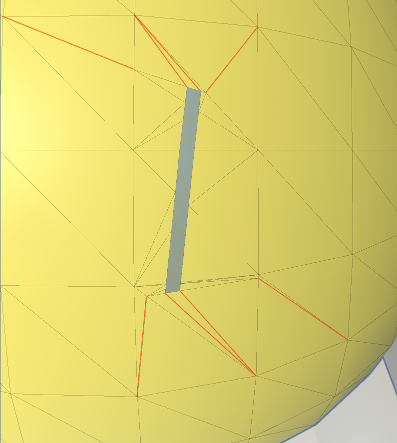
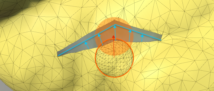
The method proposed for a progressive tear operation on a mesh model with a subsequent update of the existing particles, yields highly realistic results. However, the described particle system still misses to model the absolute physical behavior of human tissue. To model such realistic behavior, the reaction of human tissue after a tear operation would be to animate and slightly open up the wound. To achieve this type of animation, we consider an auxiliary set of newly created particles around the tear slit (see Fig. 11). These new particles will be assigned to all vertices that took part in the two triangulation passes. A slight displacement of the new particles’ anchors in a direction normal but away from the tear segments makes the animation possible.
However, the insertion of additional particles leads not only to increased realism, but also increased running times.
4. Results and Discussion
We experimented our method using various mesh models; some representative use cases are shown in Figs. 1, 2 and 3. In all cases, further cut/tear operations, soft-body deformations and/or model animations are possible. Tables 1 and 3 contain the time required to perform the algorithms for tear and cut respectively. All running times were obtained using a Windows 11 PC equipped with AMD Ryzen 7 5800H at 3.2GHZ, 16GB RAM and an Nvidia RTX 3060 (6GB RAM) graphics card. The proposed method was implemented exclusively using non-parallel CPU computations. Our methods are also partially implemented in a VR medical training application (Zikas et al., 2021), running on a modern game engine performing identical results and producing real-time frame-rates, suitable for desktop but also for VR immersive systems. In our experiments, an HTC Vive Pro tethered HMD was used to properly to validate that a satisfying immersive quality of experience (QoE) on the user’s end was achievable using our framework; this is illustrated in the video accompanying this work.
| Characteristics | Sphere | Bunny | Heart |
|---|---|---|---|
| Number of vertices | 515 | 2527 | 9747 |
| Number of faces | 768 | 4968 | 18336 |
| Number of particles | 191 | 179 | 224 |
| Operation | Running times per tear segment | ||
| Perform Tear | 0.36 ms | 3 ms | 2.54 ms |
| Update particles | 0.39 ms | 2.01 ms | 0.87 ms |
| Disconnect Particles | 0.91 ms | 1.25 ms | 2.63 ms |
| Calculate BoneWeights | 0.90 ms | 3.81 ms | 11.04 ms |
| Update Mesh | 0.07 ms | 0.24 ms | 0.76 ms |
| Total Time | 3.25 ms | 11.19 ms | 18.65 ms |
Experiments of (He et al., 2022) showed partial cutting simulations of various deformable objects, called fractures, which correspond to our tear operations. The method produces highly realistic virtual cutting simulations considering the deformable object’s fracture resistance. The scalpel cutting seems to be a little inaccurate with respect to the visualized cut. In terms of computational results, the method introduces a relatively low overhead on desktop stations while no experimentation is mentioned on demanding frame-rate systems such as VR or embedded within game engine pipelines. The experiments show (see Table 2) that for medium sized models the method’s results are close to our results, while in larger models our method is much faster.
The work of (Mitchell et al., 2015) provide cutting results for various models with no information on their mesh resolution. The experimentation of the method was run on two different desktop platforms. The running times of the method are bound by the utilization of a Newton-Raphson iterative solution scheme. In that regard, the method was not experimented in VR or game engine environments.
The (Li et al., 2021) provide real-time tearing and cutting operations on deformable surfaces. This method is mainly experimented on cloth models which differ significantly from surgical-like tear operations. The simulation involves a local/global solve of projective dynamics with the pre-computed factorization, and the factor modification process. The produced results are indeed satisfying for desktop systems, but not for VR, as the time for a cloth cut is 49ms in total.
| Model | Faces | Running Time |
|---|---|---|
| Horse | 4266 | 10.14 ms |
| Bunny (OUR) | 4968 | 11.19 ms |
| Cuboid | 18128 | 52.77 ms |
| Heart (OUR) | 18336 | 18.65 ms |
| Characteristics | Bone | Bunny | Small Cactus |
|---|---|---|---|
| Number of vertices | 516 | 2527 | 2976 |
| Number of faces | 983 | 4968 | 3000 |
| Cut Operation | |||
| Intersection Points | 64 | 356 | 186 |
| Running times | 12 ms | 17.29 ms | 13.49 ms |
5. Conclusions & Future Work
We have presented an algorithm that allows a user to perform unconstrained consecutive tears on a rigged model in VR, while preserving its ability to be deformed as a soft-body. Since our method is geometry-based, it does not require significant GPU/CPU resources, it is amenable to work in real-time VR even for low-spec devices, making it ideal for mobile VR. We expect that it will eventually pave the way to alter the modern landscape of such VR interactions, where similar operations are mostly predefined. Also, most state-of-the-art methods including physically-correct methods (e.g. Finite Element Methods) cannot be used as they require significant computing resources and/or produce low fps results, unsuitable for mobile VR applications. The proposed framework is already implemented in the MAGES SDK, running on Unity3D, publicly available for free.
In the future, we intend to further optimize our framework to work in a fraction of the current running times by utilizing GPU compute and geometry shaders, taking advantage of the parallel pipeline they offer. So far, the performance overhead by our framework during a VR session, involving high-complexity models, is minimal and in most cases negligible, due to the user’s mental preparation time between actions. As tear operations are especially useful for VR medical training scenarios, we would like to explore our algorithm’s adaptation to the collaborative needs of multi-user scenarios of such applications. Lastly, we would like to investigate the utilization of deep learning for the optimal identification of best suited clusterings, based on the model, and the action(s) the user intents to perform.
Acknowledgments
The project was partially funded by the European Union’s Horizon 2020 research and innovation programme under grant agreements No 871793 (ACCORDION) and No 101016509 (CHARITY).
References
- (1)
- Bowers et al. (2010) John Bowers, Rui Wang, Li-Yi Wei, and David Maletz. 2010. Parallel Poisson Disk Sampling with Spectrum Analysis on Surfaces. ACM Transactions on Graphics (TOG) 29, 6 (2010), 1–10.
- Bruyns et al. (2002) Cynthia D Bruyns, Steven Senger, Anil Menon, Kevin Montgomery, Simon Wildermuth, and Richard Boyle. 2002. A survey of interactive mesh-cutting techniques and a new method for implementing generalized interactive mesh cutting using virtual tools. The journal of visualization and computer animation 13, 1 (2002), 21–42.
- He et al. (2022) Sirui He, Yinling Qian, Xin Zhu, Xiangyun Liao, Pheng-Ann Heng, Ziliang Feng, and Qiong Wang. 2022. Versatile Cutting Fracture Evolution Modeling for Deformable Object Cutting Simulation. Computer Methods and Programs in Biomedicine 219 (June 2022), 106749. https://doi.org/10.1016/j.cmpb.2022.106749
- Kamarianakis and Papagiannakis (2021) Manos Kamarianakis and George Papagiannakis. 2021. An All-in-One Geometric Algorithm for Cutting, Tearing, and Drilling Deformable Models. Advances in Applied Clifford Algebras 31 (Jul 2021), 58.
- Li et al. (2021) Jing Li, Tiantian Liu, Ladislav Kavan, and Baoquan Chen. 2021. Interactive cutting and tearing in projective dynamics with progressive cholesky updates. ACM Transactions on Graphics (TOG) 40, 6 (2021), 1–12.
- Macklin et al. (2014) Miles Macklin, Matthias Müller, Nuttapong Chentanez, and Tae-Yong Kim. 2014. Unified Particle Physics for Real-Time Applications. ACM Transactions on Graphics (TOG) 33, 4 (2014), 104.
- Magnenat-thalmann et al. (1988) Nadia Magnenat-thalmann, Richard Laperrire, Daniel Thalmann, and Université De Montréal. 1988. Joint-Dependent Local Deformations for Hand Animation and Object Grasping. In In Proceedings on Graphics interface ’88. 26–33.
- Mitchell et al. (2015) Nathan Mitchell, Court Cutting, and Eftychios Sifakis. 2015. GRIDiron: an interactive authoring and cognitive training foundation for reconstructive plastic surgery procedures. ACM Transactions on Graphics (TOG) 34, 4 (2015), 1–12.
- Nealen et al. (2006) Andrew Nealen, Matthias Müller, Richard Keiser, Eddy Boxerman, and Mark Carlson. 2006. Physically based deformable models in computer graphics. In Computer graphics forum, Vol. 25. Wiley Online Library, 809–836. Issue 4.
- Papagiannakis et al. (2022) George Papagiannakis, Manos Kamarianakis, Thomas C. Sauter, Alan Chalmers, Joan Lasenby, Daniele Di Lernia, and Walter Greenleaf. 2022. Editorial: New Virtual Reality and Spatial Computing Applications to Empower, Upskill and Reskill Medical Professionals in a Post-Pandemic Era. Frontiers in Virtual Reality 3 (2022).
- Papagiannakis et al. (2018) George Papagiannakis, Nick Lydatakis, Steve Kateros, Stelios Georgiou, and Paul Zikas. 2018. Transforming Medical Education and Training with VR Using M.A.G.E.S.. In SIGGRAPH Asia 2018 Posters (Tokyo, Japan) (SA ’18). Association for Computing Machinery, New York, NY, USA, Article 83, 2 pages.
- Papagiannakis et al. (2020) George Papagiannakis, Paul Zikas, Nick Lydatakis, Steve Kateros, Mike Kentros, Efstratios Geronikolakis, Manos Kamarianakis, Ioanna Kartsonaki, and Giannis Evangelou. 2020. MAGES 3.0: Tying the Knot of Medical VR. In ACM SIGGRAPH 2020 Immersive Pavilion (Virtual Event, USA) (SIGGRAPH ’20). Association for Computing Machinery, New York, NY, USA, Article 6, 2 pages.
- Parker and O’Brien (2009) Eric G. Parker and James F. O’Brien. 2009. Real-Time Deformation and Fracture in a Game Environment. In Proceedings of the 2009 ACM SIGGRAPH/Eurographics Symposium on Computer Animation. 165–175.
- Protopsaltis and Papagiannakis (2020) A. Protopsaltis and G. Papagiannakis. 2020. Virtual Reality: A Model for Understanding Immersive Computing. Springer International Publishing, Cham, 1–4. https://doi.org/10.1007/978-3-319-08234-9_165-1
- Sifakis et al. (2007) Eftychios Sifakis, Kevin G. Der, and Ronald Fedkiw. 2007. Arbitrary Cutting of Deformable Tetrahedralized Objects. In Proceedings of the 2007 ACM SIGGRAPH/Eurographics Symposium on Computer Animation. 73–80.
- Terzopoulos et al. (1987) Demetri Terzopoulos, John Platt, Alan Barr, and Kurt Fleischer. 1987. Elastically deformable models. In Proceedings of the 14th annual conference on Computer graphics and interactive techniques. 205–214.
- Zikas et al. (2021) Paul Zikas, Manos Kamarianakis, Ioanna Kartsonaki, Nick Lydatakis, Steve Kateros, Mike Kentros, Efstratios Geronikolakis, Giannis Evangelou, Achilles Apostolou, Paolo Alejandro Alejandro Catilo, and George Papagiannakis. 2021. Covid-19 - VR Strikes Back: Innovative Medical VR Training. Association for Computing Machinery, New York, NY, USA.