Preview Reference Governors:
A Constraint Management Technique
for Systems With Preview Information
Abstract
This paper presents a constraint management strategy based on Scalar Reference Governors (SRG) to enforce output, state, and control constraints while taking into account the preview information of the reference and/or disturbances signals. The strategy, referred to as the Preview Reference Governor (PRG), can outperform SRG while maintaining the highly-attractive computational benefits of SRG. However, as it is shown, the performance of PRG may suffer if large preview horizons are used. An extension of PRG, referred to as Multi-horizon PRG, is proposed to remedy this issue. Quantitative comparisons between SRG, PRG, and Multi-horizon PRG on a one-link robot arm example are presented to illustrate their performance and computation time. Furthermore, extensions of PRG are presented to handle systems with disturbance preview and multi-input systems. The robustness of PRG to parametric uncertainties and inaccurate preview information is also explored.
Abstract
This paper presents a constraint management strategy based on Scalar Reference Governors (SRG) to enforce output, state, and control constraints while taking into account the preview information of the reference and/or disturbances signals. The strategy, referred to as the Preview Reference Governor (PRG), can outperform SRG while maintaining the highly-attractive computational benefits of SRG. However, as it is shown, the performance of PRG may suffer if large preview horizons are used. An extension of PRG, referred to as Multi-horizon PRG, is proposed to remedy this issue. Quantitative comparisons between SRG, PRG, and Multi-horizon PRG on a one-link arm robot example are presented to illustrate their performance and computation time. The robustness of PRG to disturbance previews, parametric uncertainties, and inaccurate preview information is also explored.
keywords:
Constraints management , Reference governors , Preview control , Predictive control1 INTRODUCTION
Preview control has been a subject of study in the field of control theory for many decades. The main idea behind preview control is to incorporate known or estimated information on the future values of the disturbances or references (i.e., “preview” information) in the computation of the current control command. Such preview may be computed from models or may be available from measurements. For example, in a wind turbine control application, preview information on wind velocity may be available from measurements taken elsewhere in the wind farm. Incorporating this information in the calculation of the control command can result in improved system performance [13].
Common methods for preview control are preview control [22], LQR preview control [6], and mixed - method, just to mention a few (see [2] for a comprehensive review). These methods, however, are not able to enforce pointwise-in-time state and control constraints, which is important to ensure safe and efficient system operation. A preview control method that can, in fact, enforce these constraints is Model Predictive Control (MPC) [1, 18, 3], which is an optimization-based method that can naturally incorporate preview information in the cost function [12]. Some applications of preview-MPC can be found in active suspension [11], swing leg trajectories of biped walking robots [21], and wind turbines [13]. Since MPC is computationally demanding, its applicability has been limited to systems with slow or low-order dynamics, or systems controlled by fast processors [5]. A relatively new constraint management strategy, which alleviates the above computational challenges of MPC, is the Reference Governor, also referred to as the Scalar Reference Governor (SRG) [10, 7, 14, 16, 8, 19]. It is an add-on mechanism that enforces pointwise-in-time state and control constraints by governing, whenever is required, the reference signal of a pre-stabilized closed-loop system (see Figure 1). However, standard SRG uses only the value of the reference signal at the current time and is unable to take preview information into account. This paper fills this gap and presents a novel reference governor-based solution, referred to as the Preview Reference Governor (PRG), to enforce the constraints while incorporating the preview information of the reference and disturbance signals, which yields superior transient performance as compared to SRG.
To explain PRG, we first summarize the main ideas behind SRG. The SRG employs the so-called Maximal Admissible set (MAS) [9], which is defined as the set of all initial conditions and inputs that ensure constraint satisfaction for all times. This set is computed offline. In real-time, SRG computes an optimal (See Figure 1) to maintain the system state inside the MAS and, thus, enforce the constraints. This is achieved by solving, at every time step, a simple linear program, whose solution can be computed explicitly.
Now reconsider the closed-loop plant in Figure 1, but assume that the preview information of the reference signal is available. More specifically, , are known to the controller at time , where is the “preview horizon”. We initially assume that has a single input (we will extend the theory to multi-input systems in Section 7). Similar to SRG, the goal of PRG is to select as close as possible to (to ensure that the tracking performance does not suffer) such that the output constraints are satisfied for all times. However, the PRG must take into consideration the preview information of in order to improve the tracking performance as compared to SRG. To achieve these goals, we first lift and from to in order to describe them over the entire preview horizon. Next, the system is represented based on the lifted input, and a new MAS is calculated based on this new representation. Finally, PRG is formulated as an extension of SRG, where a new optimization problem is solved based on the new MAS and a new update law is used to compute . A high-level block diagram of the PRG is shown in Figure 2, where the availability of the preview information of the reference is explicitly displayed.
As we show in this paper, PRG guarantees constraint satisfaction, recursively feasibility, and closed-loop stability. However, it may calculate conservative inputs under certain conditions, especially for long preview horizons. To overcome this issue and further improve performance, we present an extension of PRG. The extension, which we refer to as Multi-horizon PRG (abbreviated as Multi- PRG), is based on solving multiple PRGs with different preview horizons and optimally fusing the outputs of the PRGs.
We next consider the case where the system is affected by disturbances, whose preview information is available (in addition to the reference preview). The PRG solution for this case involves formulating a new MAS, wherein the disturbance preview appears explicitly as parameters of the MAS. To guarantee constraint satisfaction, the MAS is robustified to the worst-case realization of disturbances beyond the preview horizon.
In practice, systems are affected by uncertainties in the model as well as the preview information. Therefore, we also consider systems under parametric uncertainties and inaccurate preview information (in either reference or disturbance). We propose a “robust” PRG formulation to robustify the design against these uncertainties.
Finally, we propose two solutions to handle multi-input systems. The first solution comprises the same ideas as in PRG for single-input systems, except that we lift and from to , where is the number of inputs. However, as will be shown by an example, this solution might lead to a conservative response since a single optimization variable is used to govern all input channels. To overcome this shortcoming, we propose another solution, which combines the Decoupled Reference Governor scheme [15] and PRG theory. Detailed information will be explained in Section 7.
In summary, the original contributions of this work are:
-
1.
A novel RG-based constraint management scheme with preview capabilities, namely the PRG, which incorporates preview information of the references into the reference governor framework and is more computationally efficient than existing methods such as MPC or Command Governors (CG) [7];
-
2.
An extension of PRG (Multi- PRG) to further improve the performance of PRG;
-
3.
Analysis of recursively feasibility, closed-loop stability, and convergence under constant inputs.
-
4.
Comparison of the computational footprint and performance of these schemes.
-
5.
Extensions of PRG to systems with disturbance preview, parametric uncertainties, inaccurate preview information, and multi-input systems.
The following notations are used in this paper. and denote the set of all integers and non-negative integers, respectively. The identity matrix with dimension is denoted by . The variable is the discrete time. For vectors and , is to be interpreted component-wise. A zero matrix with dimension is denoted as .
2 Review of Maximal Admissible Sets And Scalar Reference Governors
2.1 Maximal Admissible Set (MAS)
Consider Figure 1, where represents the closed-loop system whose dynamics are described by:
| (1) | ||||
where is the state vector, is the input, and is the constrained output vector. Since represents the closed-loop system with a stabilizing controller, it is assumed that is asymptotically stable. Over the output, the following polyhedral constraint is imposed:
| (2) |
The MAS, denoted by , is the set of all initial states and constant control inputs that satisfy (2) for all future time steps:
| (3) |
As seen in (3), to construct MAS, is held constant for all . Using this assumption, the evolution of the output can be expressed explicitly as a function of the initial state and the constant input as:
| (4) |
Therefore, the MAS in (3) can be characterized by a polytope defined by an infinite number of inequalities, i.e.,
| (5) |
where , and . Reference [9] shows that under mild assumptions on and , it is possible to make the set (5) finitely determined (i.e., the matrices , and are finite dimensional) by constraining the steady-state value of , denoted by , to the interior of the constraint set, i.e.,
| (6) |
where is a small number. By introducing (6) in (5), there exists a finite prediction time , where the inequalities corresponding to all future prediction times () are redundant. This yields an inner approximation of (5), denoted by , which is finitely determined.
2.2 Scalar Reference Governors (SRG)
The SRG calculates based on by introducing an internal state, whose dynamics are governed by:
| (7) |
where is found by solving the following linear program (LP):
| (8) | ||||
| s.t. | ||||
From (7), the SRG computes an input based on the convex combination of the previous admissible input value (i.e., ) and the current reference in order to guarantee constraint satisfaction. Also, if the pair is admissible, then is also admissible, implying recursively feasibility of the SRG [7].
3 Preview Reference Governors (PRG) for single-input systems
In this section, the PRG for single-input systems is introduced and analyzed. In addition, PRG is compared with SRG using a numerical example to show that it can significantly improve the closed-loop system performance while enforcing the constraints. An extension of PRG to multi-input systems will be explained in Section 7. As mentioned in the Introduction, PRG is based on lifting the reference (i.e., ) and the governed reference (i.e., ) from to and representing the system using the lifted input. Based on the new representation, a modified maximal admissible set is characterized and a new formulation of reference governor is proposed, as explained in detail below.
Consider the system shown in Figure 2. Assume , , , are available at time , where is the current value of the setpoint and are the preview information, and represents the preview horizon. Note that corresponds to the case where no preview information is available. We now define the lifted signals (shown in Figure 2) and , as follows:
| (9) |
Using the lifted signals, can be equivalently expressed as:
| (10) | |||
We now describe the Maximal Admissible Set (MAS) for this system. Recall from (3) that in order to characterize MAS in the SRG framework, it is assumed that is held constant for all time. This will ensure that the optimization problem (8) will always have a feasible solution, namely . In order to extend these ideas to PRG, we assume that may vary within the preview horizon, but is held constant beyond the preview horizon. Therefore, the dynamics of are chosen to be:
| (11) |
with initial condition , where is defined by:
| (12) |
This choice of , together with the definition of in (9), enforce that for all , . With these dynamics, the new MAS is defined by:
| (13) | ||||
Similar to (6), a finitely determined inner approximation of this set can be computed by tightening the steady-state constraint (to prove finite determinism, note that after time steps, converges to a constant, which reduces the problem to that in the standard MAS theory). In the rest of this paper, with an abuse of notation, we use to denote the finitely determined inner approximation (instead of using ).
With the new MAS defined, we are now ready to present the PRG formulation. Recall that the SRG computes using the update law in (7), where is obtained by solving the linear program (LP) in (8). Note from (7) that can be regarded as the internal state of the SRG (i.e., the SRG strategy consists of a single internal state). To extend these ideas to PRG, we introduce new states in the formulation, where the state update law is as follows:
| (14) |
where is the solution of the following linear program:
| (15) | ||||||
| s.t. | ||||||
An explicit algorithm, similar to the one in SRG [15], can be developed to solve this LP efficiently (see Section 5 for details). The PRG solves the above LP at every time step to compute , updates using (14), and applies the first element of to the system . Note that the variables in the LP in (15) at time step are , , and .
Remark 1.
When , PRG reduces to SRG because turns into the scalar with value in this case. Therefore, PRG is a proper extension of SRG.
Several important properties of the PRG are described in the following proposition.
Proposition 1.
The PRG formulation is recursively feasible, bounded-input and bounded-output stable (BIBO), and for a constant , converges.
Proof.
To show recursively feasibility, consider the update law (14). As can be seen, implies that , which matches the dynamic of that is assumed in (see (13)). Positive invariance of implies that if the pair is admissible, then is also admissible. In conclusion, is always a feasible solution to the LP in (8), implying recursively feasibility of the PRG. As for BIBO stability, recall that is the convex combination of and the current reference . Thus, if is bounded, then so is . This, together with the asymptotic stability of , implies BIBO stability of the system. To prove the convergence property, assume . From (14), it can be shown that every element in is monotonic and bounded by . Thus, must converge to a limit. Note that, since the closed-loop system is asymptotically stable, and would also converge. ∎
Remark 2.
Note that the definition of in (9) is consistent with the delay structure in the dynamics (11)–(12). However, the definition in (9) may appear inconsistent with the update law in (14) because the delay structure vanishes when . We remark that this is not an error. The definition in (9) and the dynamics in (11)–(12) are only introduced to construct . For real-time implementation, should not be thought of as defined by (9), but instead should be thought of as the PRG’s internal states.
Remark 3.
For the case where the state of (i.e., shown in Figure 2) is not measured, standard Luenberger observers can be designed to estimate the state.
We now illustrate the PRG using a numerical simulation of a one-link arm robot, shown in Figure 3. A state-space model of the arm is given by:
| (16) |
where , are the states and (i.e., external torque) is the control input. For this example, we assume that both states are measured (if not, an observer can be designed).
In order to design a controller and consequently implement the PRG, the system model (16) is first discretized at . Then, a state-feedback controller with a pre-compensator is applied to ensure that the output, , tracks the desired angle, , perfectly, that is: This results in the closed-loop system shown in Figure 2. We simulate a trajectory-following maneuver, wherein we use the PRG to ensure that the output, , remains within . The preview horizon, , is chosen to be (i.e., seconds). We assume that the preview information is available from the given pre-set trajectory.
The comparison between the performance of PRG and SRG is shown in Figure 4. As can be seen, given by PRG is closer to (less conservative) when . This is because when , the PRG has the future information that the reference would drop down to in future time steps so that it allows a larger than SRG. For the same reason, given by PRG is less conservative when .

Figure 4 shows a limitation of PRG as well. Specifically, it can be seen that when , given by PRG can not reach , even though is an admissible input. To explain the root cause of this behavior, note that when , the preview information available to the PRG is that drops down to at and stays constant afterwards (the increase of back to 0 at is beyond the preview horizon and unavailable to PRG). To enforce the lower constraint for , the PRG calculates a smaller than 1. However, since affects all elements of (see (14)), this leads to a that is different from when , leading to a conservative solution.
Of course, the above limitation of PRG can be addressed by decreasing the preview horizon . However, if is too short, the tracking performance of the system might not be improved significantly as compared with SRG. In order to have the superior system performance while addressing the above limitation of PRG, we provide an extension of PRG in the following section.
4 Multi-Horizon PRG (Multi- PRG)
To overcome the limitation of PRG described in the previous section and improve performance, this section introduces the Multi-Horizon Preview Reference Governor (Multi- PRG). As the name suggests, instead of having a single preview horizon, multiple preview horizons are considered. For each horizon, a MAS is characterized, and multiple PRGs are solved at each time step, one for each MAS. A technical challenge for this approach is that ’s for different preview horizons would have different dimensions and different interpretations. In addition, a practical challenge is that storing multiple MASs may lead to a significant increase in the memory requirements. Our novel solution overcomes these challenge by unifying the ’s so that only one MAS is required, and fusing the PRG solutions in a special way to guarantee constraint satisfaction and recursively feasibility.
To begin, consider the following set of preview horizons: . Let be defined as in (13), i.e., the MAS of the lifted system with preview horizon . We first show that there exists a simple relationship between , , and . Recall from (13) and (9) that in order to construct , it is assumed that is held constant beyond the preview horizon (i.e., after ). Similarly, to construct , it is assumed that is held constant after . Thus, and have the following relationship:
where denotes the bidirectional implication and is the last element in . Therefore, given this relationship, we only need to compute and store .
We now introduce the Multi- PRG, which solves PRGs at each time step, one for each . All PRGs use the same MAS, namely , as justified above. To provide more details, recall from Section 3 that PRG contains an internal state with an update law given by (14). Similarly, we introduce an internal state, denoted here by , for the Multi- PRG. PRG in the Multi- PRG framework assumes the update law:
| (17) |
where is defined the same as (12) but with , and is the lifted version of at time (defined as in (9)). The matrix is introduced above to force the control inputs beyond the preview horizon to be constant (this is to maintain consistency with the fact that PRG has a preview horizon of length ). The matrix that achieves this is:
where is a matrix with zeros everywhere except the rightmost columns, which are given by . In the update law (17), for PRG , the scalar is computed by solving the following LP:
| (18) | ||||
To fuse the solutions of the PRGs, the maximum value among is selected, denoted by . The index that corresponding to is denoted by . Then, the final update law of Multi- PRG is obtained by fusing the PRGs as follows:
This formulation maintains recursively feasibility. Indeed, suppose PRG is the PRG that computes at time step . Then, the same PRG can calculate a feasible solution at time , due to the recursively feasibility of the PRG formulation, which was proven in Proposition 1.
Note that not all PRGs in the Multi- PRG formulation will have feasible solutions at every time step. If a feasible solution to these PRGs does not exist, ’s for these PRGs are set to be . Note also that even though multiple preview horizons are considered in Multi- PRG, only is required to be computed and stored offline, implying that if for Multi- PRG is equal to for PRG, then the memory requirements of the two formulations are the same. We will study the processing requirements in the next section.
The simulation results of Multi- PRG on the one-link arm robot example are shown in Figure 5. For comparison, the results of the implementation of PRG with is also provided (this is the same as Figure 4). For the sake of illustration, we consider the extreme case where the Multi- PRG uses all preview horizons between 0 and 25; i.e., and , , …, .

From Figure 5, the outputs for both Multi- PRG and PRG satisfy the constraints, as expected. However, from the bottom plot of Figure 5, it can be seen that when , given by Multi- PRG reaches while computed by PRG is above . The reason for this behavior is that when , the PRG corresponding to computes , which leads to . Note that the actual performance improvement (as seen on the output plot) is not large for this specific example but it could be large in general.
Next, we will discuss the impact of the value of in the Multi- PRG on the system performance. Consider two extreme cases for the sake of illustration: first, and are chosen to be and (i.e., ); second, are chosen to be all numbers from to (i.e., ). The reason is selected is that the preview horizon in this case is (recall the sample time is ), which is longer than the variation of the reference in our example, and can clearly show the difference of the system performance between the two cases. The comparison between the two cases implemented on the one-link arm robot example is shown in Figure 6, which demonstrates performance improvements when a larger is used. Generally, when the preview horizon is longer than the expected variations of the reference, it is better to use the Multi- PRG formulation with a larger . However, this leads to an increase in the computational burden, which is discussed next.

5 Computational considerations
In this section, we provide a comparison between the computation time of PRG, Multi- PRG, and standard SRG by simulating the one-link arm robot example with all three methods. Recall that SRG and PRG require the solution to one linear program (LP) at each time step, while Multi- PRG requires the solutions to LP’s ( for our example). However, we do not use generic LP solvers to solve them. Instead, we use the Algorithm presented in [15] to solve the LPs in SRG and Algorithm 1 below to solve the LPs in PRG. The LPs in Multi- PRG can be solved using a similar algorithm. The notation in Algorithm 1 is as follows. It is assumed that is finitely determined and given by polytopes of the form (5). In addition, denotes the number of rows of , , and .
We simulate the one-link arm robot example with all three methods, namely SRG, PRG, and Multi- PRG. All simulations were performed for 150 time steps in Matlab on an Apple Macbook Pro with GHz Intel Core i5 processor and GB memory. In order to eliminate the effects of background processes running on the computer, each of the above experiments were run times and the averages are calculated. We calculate the per-timestep averages and maximums of each of the three methods. The results are shown in Table 1. As can be seen, PRG runs two orders of magnitude slower than SRG (because the matrices that arise in the computations are larger). The Multi- PRG is slower by one order of magnitude (because PRGs are solved at each time step).
Finally, to provide a comparison of these computation times with those of other existing preview control methods, we simulate the one-link arm robot example with the PRG replaced by a Command Governor (CG). Similar to MPC, a CG solves a Quadratic Program (QP) at each time step to directly optimize over . In addition, similar to MPC, it can incorporate preview information into the cost function. In brief, our CG solves the following QP:
| minimize | |||
| s.t. |
where . We simulate the system with above CG. The QP above is solved at every time step using explicit Multi-Parametric Quadratic Programming (MPQP), which is introduced in [23]. The computation times of CG are shown in Table 1. As can be seen, CG is one order of magnitude slower than Multi- PRG. Note that we also implemented online QP for the CG with , provided by MPT3 Toolbox in Matlab and Gurobi, and found that the computation times for both cases were longer than that of MPQP.
| SRG | PRG () | |
| avg | s | s |
| max | s | s |
| Multi- PRG | CG | |
| avg | s | |
| max | s |
6 Robust Preview Reference Governor
In this section, PRG is extended to systems with disturbance preview, as well as systems with parametric uncertainties and preview information uncertainties.
6.1 Preview Reference Governor with Disturbance Preview
In previous sections, we considered systems in which the preview information of the reference signal is available. However, there are situations wherein preview information of disturbance signals may be available as well. For example, in printing systems, the effect of paper (i.e., the disturbance) on the heating or charging systems are known with some preview, since the timing of the paper leaving the printing tray is precisely controlled [4]. Hence, in this section, we consider systems where preview information of disturbances is available within a given preview horizon. For simplicity, we do not consider preview for the reference signal, though the results can be combined with those of the previous sections to consider preview on both references and disturbances.
Consider a system with additive bounded disturbance given by:
| (19) | ||||
where and is a compact polytopic set with origin in its interior. Essentially, we incorporate the disturbance preview into the RG formulation as follows: the maximal admissible set (MAS) is characterized as a function of the current state, input, and the known disturbances within the preview horizon. The set is then shrunk to account for the worst-case realization of the unknown disturbance beyond the preview horizon. Specifically, the robust MAS for systems with disturbance preview can be defined as:
| (20) | ||||
To compute this set, define for , , and for , where represents the Pontryagin subtraction [10]. Then, the condition in (20) can be characterized equivalently by:
where is defined as:
Note that if , PRG with previewed bounded disturbance reduces to robust SRG with unknown bounded disturbance. In summary, by shrinking the MAS to take the worst case disturbance into consideration, robust PRG guarantees constraints satisfaction for all values of disturbance beyond the preview horizon.
Proposition 2.
The robust PRG formulation to disturbance previews is BIBO stable, recursively feasible, and for a constant , converges.
Proof.
Similar to the proof for Proposition 1 ∎
We now illustrate the above idea with the one-link arm robot example. The disturbance is assumed to come from the joint torque, i.e. and . We also assume that the disturbance satisfies . For the purpose of simulations, the disturbance is generated randomly and uniformly from the interval . The results of PRG with the disturbance as the preview information are shown in Figure 7. Two preview horizons are chosen, namely and in order to illustrate the relationship between the system performance and the length of the preview horizon. For comparison, Figure 7 also shows the response of robust SRG with unknown bounded disturbance (i.e., no preview).
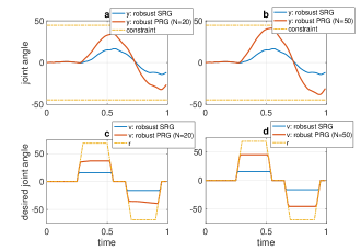
The following observations can be made. First, the output from all methods satisfy the constraints for all time steps, as expected. Second, it can be seen that given by PRG is closer to (less conservative) than that of SRG. The reason is that the constraint set for PRG with disturbance preview is less conservative than that for SRG with unknown disturbance. Third, the longer the preview horizon, the better the performance (less conservative) becomes.
6.2 Robust PRG for systems with Parametric Uncertainties
Reconsider system in Figure 2, but now with modeling uncertainty on the and matrices:
| (21) | ||||
where the pair is assumed to belong to an uncertainty polytope defined by the convex hull of the matrices:
where is the number of vertices in the uncertainty polytope. It is shown in [20] that a robust MAS can be constructed for this uncertain system. We note that a similar idea can be implemented for the PRG. Similar to (10), we write the dynamics in terms of the lifted input, but now we consider the uncertainties:
| (22) | ||||
Then, the pair must belong to a convex hull of the following matrices:
where By doing this, the method in [20] can be used to compute the robust MAS for PRG with system uncertainties. For the sake of brevity, we will not provide numerical examples in this section.
Proposition 3.
The robust PRG formulation described above is BIBO stable, recursively feasible, and for a constant , converges.
6.3 PRG for Systems with Uncertain Preview Information
In previous sections, we assumed that the preview information is accurate along the preview horizon. However, this assumption might not hold in practice since the preview information may come from inaccurate measurements or uncertain models. In this section, we present an extension of PRG that can handle inaccurate preview information of references. As can be seen from (15), if has incorrect values, then will be calculated incorrectly. The implication of this is that, in the next time step, will be computed based on the delayed version of this incorrect , which, for example, might cause to change before does. This behavior is unacceptable for most systems. Note that the constraints will still be satisfied; however, as argued above, performance may suffer. Thus, our solution in this section focuses on avoiding this loss of performance when the preview information is inaccurate. Essentially, we achieve this goal by modifying the update law for .
To begin, we assume that at time , is accurately known, but there is uncertainty on the value of along the preview horizon, i.e., are inaccurate. To accommodate this uncertainty, we modify (12) to:
| (23) |
where are tuning parameters to account for preview uncertainties. This means that instead of the delayed structure of (12), now evolves such that the value of at each time along the preview window is a convex combination of the value at that time and the values in the previous times. This effectively incorporates “forgetting” into the formulation to counteract the uncertainties in preview information. We tune according to the relative level of uncertainty on the -th preview information, . Specifically, if the uncertainty is large, is chosen to be close to . If this is the case, PRG with the new matrix (i.e., (23)) will turn to SRG. If is very accurate, on the other hand, will be chosen close to . Then, PRG with the new will turn to standard PRG (as shown in Section 3). Thus, robust PRG is a proper extension of both standard PRG and SRG. Note that typically the level of uncertainty on increases along the preview horizon, which means that the sequence of is increasing.
The construction of and the computation of are the same as (13) and (18), except that is changed from (12) to (23). Now, we will illustrate this approach using the one-link arm robot example (see the example in Section 3). Suppose first that the preview horizon, , is equal to . The slice of at is shown in Figure 8. The red region corresponds to the slice of given by the standard PRG at . The green region represents the slice of given by the robust PRG at , where we have chosen . Note that in this case (), the matrix has only one .

The situation we consider is as follows. Suppose at , the preview information is given by (yellow dot in Figure 8). However, assume that the actual preview information is (purple dot), which is unknown to the PRG. Note that since we assume that the current information is accurate. Obviously, ’s given by standard PRG and robust PRG (discussed in previous paragraph) will be equal to (i.e., ) since is in both MASs (red and green regions in Figure 8). In the next time step (), if , given by standard PRG (i.e., (15)) is a convex combination between the delay version of (i.e., ) and . For robust PRG, is a convex combination between and . Note that if the uncertainty is large, would be chosen close to and will be close to . By doing so, robust PRG decreases the impact of the wrong previous information on the computation of current by multiplying the previous information with values smaller than (i.e., ’s).
Remark 4.
By comparing (23) and (12), it can be seen that, for robust PRG, the last element in is multiplied by a value less than and the first element in is multiplied by a value that is not equal to , which is different from those in standard PRG. This implies that the MAS for robust PRG will stretch along the axis and shrink along the axis as compared with the MAS for standard PRG (as shown in Figure 8). Thus, unlike the robust MAS for disturbances and polytopic uncertainties, it is not the case that the robust MAS for inaccurate preview information is a subset of the MAS for standard PRG.

We now perform numerical simulations of the one-link arm robot example. We change the preview horizon to for the sake of illustration. We consider the scenario where the assumed preview information is larger than the actual preview information along the preview horizon. The is chosen to be:
| (24) |
Note that several sets of ’s were tried and the above was found to result in the best performance (will be explained later). We acknowledge that there are other possibilities to choose and finding the optimal set of s will be explored in future work. The comparison between standard PRG and robust PRG is shown in Figure 9. It can be seen that when , given by robust PRG (blue line) is closer to than that given by standard PRG (red line). The reason for the behavior can be explained as follows. At , ’s given by standard PRG and robust PRG are both equal to . Recall that the first element in is accurate and the rest elements in are inaccurate. Then, in the next time step, for standard PRG, is calculated as a convex combination between the delayed version of (inaccurate) and . With , is calculated as . For robust PRG, is computed as a convex combination between , where is shown in (24), and . With , . Note that by increasing the value of in (24) (i.e., ), would become closer to . However, the tracking performance would not be improved significantly as compared with SRG.
Proposition 4.
The robust PRG formulation to inaccurate preview information is BIBO stable, recursively feasible, and for a constant , converges.
Proof.
The proof of BIBO stable and recursively feasibility are the same as the proof for Proposition 1. To prove the convergence property, assume . Note that , where is a static matrix, since shown in (23) is a stochastic matrix. Then, from (14), it can be shown that every element in is monotonic increasing after converges and bounded by . Thus, must converge to a limit. ∎
7 PRG for multi-input system
In this section, we will briefly introduce an extension of PRG to multi-input systems. One possible, straightforward solution is to apply the PRG ideas from above directly to multi-input systems. However, as will be shown in an example later, this approach might lead to a conservative response since PRG uses a single decision variable to simultaneously govern all the channels of the multi-input system. To address this shortcoming, we propose another solution, which combines the PRG idea with the Decoupled Reference Governor (DRG) scheme [15]. Detailed information will be introduced below.
To begin, suppose that system in Figure 2 has inputs, i.e., . Let us denote the preview horizon for the different inputs (i.e., ) by , respectively. Define the lifted signals and as follows:
| (25) | |||
We can select the dynamics of to be the same as (11) but with constructed as:
| (26) |
where () is defined the same as (11), with replaced by .
The construction of and the calculation of are the same as (13) and (15), except that is modified to (26). Below, we will provide an illustrative example to show that this approach works as required but might lead to a conservative response. Consider a two-link arm robot, which has dynamics as follows [17]:
| (27) |
where and are the external torque and the joint angle for the first link, respectively. Similarly, and are the torque and the joint angle for the second link, respectively. The constrained outputs are and . The constraints on both joint angles are . To implement PRG, the system is first discretized at . Then, a state feedback controller is designed to ensure that and track desired joint angles, and , respectively, that is:
The preview horizons for both references are chosen to be (i.e., ). The simulation results of PRG of this multi-input system are shown in Figure 10. As can be seen, the outputs both satisfy the constraints, as required. However, when , can not reach , which is shown by the purple dashed line in the bottom plot, even though (i.e., red line in the top plot) is far from the lower constraint. This is caused by the fact that (i.e., the blue line in the top plot of Figure 10) reaches the constraint when , which results in being equal to . Since a single is used in PRG scheme, can not reach .

From the above discussion, it can be seen that this approach might lead to a conservative response. To address this shortcoming, we propose another method, which combines the PRG theory with the DRG scheme in [16]. As a quick review, DRG is based on decoupling the input-output dynamics of the system, followed by the application of SRG to each decoupled channel. In our solution, instead of using SRGs to govern the decoupled channels, we use the PRG presented in Section 3. This leads to the block diagram shown in Figure 11. For ease of presentation, we will assume the system is square (i.e., equal number of inputs and outputs). Non-square systems can be handled as well by considering the DRG scheme for non-square systems presented in [16].
Thus, we suppose the closed-loop system is described by a transfer function system matrix with elements . As shown in Figure 11, we decouple by introducing , leading to a diagonal system: . As discussed in [15], there are several ways to construct . For the sake of brevity, we only consider the case where is given by: . Note that the same process to combine PRG idea and DRG scheme can be applied to other formulations of as well. Then, different PRGs for single-input systems (see Section 3) are implemented, one for each . Finally, as discussed in [15], is introduced to ensure that and are close if is not constraint-admissible. Simulation results of the second approach on the two-link arm robot are shown in Figure 12. As can be seen, the outputs satisfy the constraints, as required. Also, when , reaches , which is represented by the purple dashed line in the bottom plot. This behavior can be explained as follows. When , the PRGs have the future information that will drop down to at and then go up towards at (recall that ). Also, from the top plot of Figure 12, it can be seen that when , (red line in the top plot) does not reach the lower constraint, which leads to (recall that refers to the optimization variable given by the second PRG). Hence, reaches .

Note that both approaches discussed above can be easily extended to multi- PRG by combining DRG scheme and Multi-N PRG idea.
8 CONCLUSIONS AND FUTURE WORKS
In this work, a reference governor-based method for constraint management of linear systems is proposed. The method is referred to as Preview Reference Governor (PRG) and can systematically account for the preview information of reference and disturbance signals. The method is based on lifting the input of the system to a space of higher dimension and designing maximal admissible sets based on the system with lifted input. We showed a limitation of PRG and proposed an alternative method, which we refered to as Multi-horizon PRG (multi- PRG), to overcome the limitation. Disturbance previews, parametric uncertainties, and inaccurate preview reference information were also addressed. We also showed that the PRG for multi-input systems using the lifting idea (i.e., first solution in Section 7) might cause conservative response. Thus, we proposed another method, which combines the Decoupled Reference Governor scheme and PRG, to overcome this limitation.
Future work will explore preview control in the context of Vector Reference Governors, as well as finding the optimal set of s that gives the best performance in our robust PRG formulation. We will also investigate the extension of PRG to nonlinear systems.
References
- [1] Alberto Bemporad, Francesco Borrelli, Manfred Morari, et al. Model predictive control based on linear programming, the explicit solution. IEEE transactions on automatic control, 47(12):1974–1985, 2002.
- [2] Nidhika Birla and Akhilesh Swarup. Optimal preview control: A review. Optimal Control Applications and Methods, 36(2):241–268, 2015.
- [3] Eduardo F Camacho and Carlos Bordons Alba. Model predictive control. Springer Science & Business Media, 2013.
- [4] ShiNung Ching, Yongsoon Eun, Eric Gross, Eric Hamby, Pierre Kabamba, Semyon Meerkov, and Amor Menezes. Modeling and control of cyclic systems in xerography. In Proceedings of the 2010 American Control Conference, pages 4283–4288, 2010.
- [5] Stefano Di Cairano. An industry perspective on mpc in large volumes applications: Potential benefits and open challenges. IFAC Proceedings Volumes, 45(17):52–59, 2012.
- [6] Asif Farooq and David JN Limebeer. Path following of optimal trajectories using preview control. In Proceedings of the 44th IEEE Conference on Decision and Control, pages 2787–2792. IEEE, 2005.
- [7] Emanuele Garone, Stefano Di Cairano, and Ilya Kolmanovsky. Reference and command governors for systems with constraints: A survey on theory and applications. Automatica, 75:306–328, 1 2017.
- [8] Emanuele Garone and Marco M Nicotra. Explicit reference governor for constrained nonlinear systems. IEEE Transactions on Automatic Control, 61(5):1379–1384, 2015.
- [9] E. G. Gilbert and K. T. Tan. Linear systems with state and control constraints: the theory and application of maximal output admissible sets. IEEE Transactions on Automatic Control, 36(9):1008–1020, Sep 1991.
- [10] Elmer G Gilbert and Ilya Kolmanovsky. Discrete-time reference governors for systems with state and control constraints and disturbance inputs. In Proceedings of 1995 34th IEEE Conference on Decision and Control, volume 2, pages 1189–1194. IEEE, 1995.
- [11] C. Gohrle, A. Schindler, A. Wagner, and O. Sawodny. Design and vehicle implementation of preview active suspension controllers. IEEE Transactions on Control Systems Technology, 22(3):1135–1142, May 2014.
- [12] Christoph Göhrle, Andreas Wagner, Andreas Schindler, and Oliver Sawodny. Active suspension controller using mpc based on a full-car model with preview information. In 2012 American Control Conference (ACC), pages 497–502. IEEE, 2012.
- [13] Arne Koerber and Rudibert King. Combined feedback–feedforward control of wind turbines using state-constrained model predictive control. IEEE Transactions on Control Systems Technology, 21(4):1117–1128, 2013.
- [14] I. Kolmanovsky, E. Garone, and S. Di Cairano. Reference and command governors: A tutorial on their theory and automotive applications. In 2014 American Control Conference, pages 226–241, June 2014.
- [15] Yudan Liu, Joycer Osorio, et al. Decoupled reference governors for multi-input multi-output systems. In 2018 IEEE Conference on Decision and Control (CDC), pages 1839–1846. IEEE, 2018.
- [16] Yudan Liu, Joycer Osorio, and Hamid R. Ossareh. Decoupled reference governors: A constraint management technique for mimo systems, 2020.
- [17] Samia M Mahil and Ahmed Al-Durra. Modeling analysis and simulation of 2-dof robotic manipulator. In 2016 IEEE 59th International Midwest Symposium on Circuits and Systems (MWSCAS), pages 1–4. IEEE, 2016.
- [18] Manfred Morari and Jay H Lee. Model predictive control: past, present and future. Computers & Chemical Engineering, 23(4-5):667–682, 1999.
- [19] Hamid R Ossareh. Reference governors and maximal output admissible sets for linear periodic systems. International Journal of Control, 93(1):113–125, 2020.
- [20] Bert Pluymers, John A Rossiter, Johan AK Suykens, and Bart De Moor. The efficient computation of polyhedral invariant sets for linear systems with polytopic uncertainty. In Proceedings of the 2005, American Control Conference, 2005., pages 804–809, 2005.
- [21] Shuhei Shimmyo, Tomoya Sato, and Kouhei Ohnishi. Biped walking pattern generation by using preview control based on three-mass model. IEEE transactions on industrial electronics, 60(11):5137–5147, 2012.
- [22] Kiyotsugu Takaba. A tutorial on preview control systems. In SICE 2003 Annual Conference (IEEE Cat. No. 03TH8734), volume 2, pages 1388–1393. IEEE, 2003.
- [23] Petter Tøndel, Tor Arne Johansen, and Alberto Bemporad. An algorithm for multi-parametric quadratic programming and explicit mpc solutions. Automatica, 39(3):489–497, 2003.