Prediction of shock wave configurations in compression ramp flows
Abstract
Here, we provide a theoretical framework revealing that a steady compression ramp flow must have the minimal dissipation of kinetic energy, and can be demonstrated using the least action principle. For a given inflow Mach number and ramp angle , the separation angle manifesting flow system states can be determined based on this theory. Thus, both the shapes of shock wave configurations and pressure peak behind reattachment shock waves are predictable. These theoretical predictions agree excellently with both experimental data and numerical simulations, covering a wide range of and . In addition, for a large separation, the theory indicates that only depends on and , but is independent of the Reynolds number and wall temperature . These facts suggest that the proposed theoretical framework can be applied to other flow systems dominated by shock waves, which are ubiquitous in aerospace engineering.
keywords:
Authors should not enter keywords on the manuscript.1 Introduction
Compression ramp flows are canonical complex flows of interactions between shock waves and boundary layers and are ubiquitous in aerospace engineering (Babinsky & Harvey (2011)). As Figure 1 (a) shows, when a large separation occurs, the flow pattern will change significantly, and such a shock pattern was classified as type VI by Edney (1968). In this process, a recirculation region, called a ‘separation bubble’, will emerge and induce two new shock waves, i.e., the separation and reattachment shock waves. As a result, spatial distributions of physical quantities, such as the flow pressure , will change. The geometrical features of the separation bubble have a significant contribution that its size (which can be described by the area of the bubble ) and shape (the separation angle ) determine the range and intensity of the wall pressure , respectively, as shown in Figures 1 (b), (c), and (d). Many numerical (Hung & MacCormack (1976); RUDY et al. (1989); Olejniczak & Candler (1998); Deepak et al. (2013)) and experimental (Holden (1966); Lewis et al. (1968); Délery et al. (1986); Mallinson et al. (1997)) studies have been conducted and they primarily focused on the size (Burggraf (1975); Rizzetta et al. (1978); Daniels (1979); Korolev et al. (2002)) and internal details (Smith & Khorrami (1991); Korolev et al. (2002); Neiland et al. (2008); Shvedchenko (2009); Gai & Khraibut (2019)) of the separation bubble. However, only a few of these studies discuss the bubble shape , even though it is a pivotal parameter in determining the flow field.
Because the emergence of the separation bubble decreases the homogeneity degree of the flow system (symmetry-breaking), the process from the attachment state () to the separation state (), shown in Figure 1 (a), can be analogous to a type of phase transition, where manifesting the flow states is actually an order parameter — the concept introduced by Landau (1937) for phase transition (see Goldenfeld, 2018, pp. 136-137). Therefore, the separation bubble is a ‘dissipative structure’—the concept proposed by Prigogine (1978) for structures emerging in systems far from equilibrium—and its self-organization process must be governed by the synergic principle of the subsystems (0,1,2, and 3 that are divided by shock waves and shear layers), shown in Figure 1 (b). From this perspective, this principle is expected to be expressed in an integral form, consisting of the differential governing equation, so that the synergy of this flow system can be described and understood easily. For this purpose, we use the least action principle to establish the equivalent form between the differential and integral scales.
In this paper, we demonstrate that the synergic principle of this flow system is the minimal dissipation theorem. Based on this theorem, the separation angle can be determined; subsequently, the flow patterns are predictable. The proposed theoretical predictions agree excellently with the numerical and experimental results for a wide range of Mach numbers and ramp angles . Additionally, the theorem indicates that shapes of shock wave configurations induced by large separations are independent of the Reynolds number and the wall temperature .

2 The minimal dissipation theorem
In this section, we will demonstrate that the flow system has minimal dissipation. The steady states of the flow system satisfy the following equations:
| mass equation: | (1) | |||
| momentum equation: | (2) | |||
| kinetic energy equation: | (3) |
where , , , , , , and are the density, velocity, body force, pressure, dilatation viscosity, shear viscosity, and heat flux of the flow, respectively. , , and are the velocity divergence, strain-rate tensor, and stress tensor, respectively. is the dissipation of kinetic energy:
| (4) |
Helmholtz and Rayleigh (Helmholtz (1868); Rayleigh (1913); Serrin (1959)) proved that, for an incompressible viscous fluid, if the acceleration can be derived by a potential ( or ), it should possess minimal dissipation, which is the well-known Helmholtz-Rayleigh minimal dissipation theorem. He et al. (1988) generalized this theorem to compressible flows (Wu et al. (2007)). Here, we demonstrate the proof process concisely, and provide conditions that compression flows should satisfy. The total dissipation in a control volume bounded by is considered, where is nondeformable or the flow on (if is deformable) is nondissipative. With the constraint provided by Equation (1), the variation of can be written as
| (5) |
where is a Lagrangian multiplier and is the Lagrangian. Because and are the two independent variables of , the Eular-Lagrangian equations are
| (6) | |||
| (7) |
If a flow satisfies (i) ; (ii) , i.e., the body force can be derived by a potential ; (iii) or , i.e., the flow is barotropic, the viscous force can then be derived by a potential from function (2), i.e., . Thus, with chosen as , Equations (6) and (7) can be exactly rearranged to the momentum equation (2) and kinetic energy equation (3), respectively. Therefore, compressible flows satisfying (i), (ii), and (iii) must have minimal dissipation.
For a flow passing through a straight shock wave, the acceleration can be decomposed into two parts relative to the shock front, i.e., the vertical component and tangential one (consider two-dimensional cases). Because only changes perpendicularly through the shock, there must be and , then , satisfying condition (i). Condition (ii) is also satisfied because the body force is gravity, which can be negligible. Note that and are both perpendicular to the shock front, i.e., ; thus, condition (iii) is satisfied. Therefore, a steady flow across a straight shock wave has minimal dissipation. A corollary of this demonstration is that, if the total dissipation of a steady flow is only contributed by shock waves, this flow should have minimal dissipation. A piece of evidence is that, although two (one weak and one strong) oblique shock waves are both theoretically possible for the same deflection angle, the observable shock wave, in practice, is always the weak one.
3 Dissipation of the flow system
In this section, we will demonstrate that, for a large separation, the total dissipation of this flow system is primarily contributed by shock waves, and show the dependency of on .
As 1 (b) shows, four types of flow structure probably generate dissipation, i.e., (i) shock waves, (ii) shear layers, (iii) the separation bubble, and (iv) the expansion fan (behind the triple point ). For (i), a shock wave with length , the dissipation can be estimated as using Equation (4), where , , , and are the characteristic length, thickness, viscosity, and velocity difference of this shock, respectively. For (ii), a shear layer with length , its dissipation can also be estimated, i.e., , where , , and are the characteristic thickness, viscosity, and velocity difference of this shear layer, respectively. Because , , , and , dissipations induced by shear layers are negligible relative to those induced by shock waves. For (iii), a separation bubble with characteristic length (i.e., ), its dissipation can be estimated as , where is the characteristic viscosity of the bubble. Although its internal vortex structure may be complex, its characteristic velocity is always very small relative to , i.e., . In consideration of , the dissipation induced by the separation bubble can be negligible as well. For (iv), an expansion fan with area , its dissipation can be calculated using the relation , i.e., the deformation of the energy equation (Wu et al. (2007)), where , , and are the entropy production, temperature, and heat conductivity of the flow, respectively. Because the flow passing through is an isentropic process, and the heat flux on the boundary of is zero, there must be . Therefore, the dissipation induced by the expansion fan is zero. In this flow system, the appropriate control volume is chosen and is bounded by , , , and , as shown in Figure 1 (b). Because the total dissipation in is primarily contributed by shock waves and , a steady flow in should have minimal dissipation, which implies of a steady state should cause shock waves and to dissipate minimal kinetic energy.
Subsequently, we will illustrate how the total dissipation depends on . By integrating function (3) across the shock wave perpendicularly, we obtain the dissipation induced by a shock wave per unit length:
| (8) | ||||
where and are the kinetic energy loss and the negative work of pressure, respectively, implying that one portion of the kinetic energy loss is stored as the potential energy and the other is dissipated. In Equation (LABEL:eq:dissipation_per_unit_length), , , and are the Mach number, acoustic velocity, and shock angle, respectively. The subscripts ‘a’ and ‘b’ are the locations ahead of and behind a shock wave, respectively. As 1 (b) shows, ‘a’ and ‘b’ correspond to ‘0’ and ‘1’ for shock , and to ‘1’ and ‘2’ for , respectively. Quantities in Equation (LABEL:eq:dissipation_per_unit_length) satisfy the following:
| (9) |
where and are the shock angles of and , respectively, and is the deflection angle of the flow across . , , , , and are the classical Rankine-Hugoniot relations (Rankine (1870, 1887)):
| (10) | ||||
Therefore, for a given inflow Mach number and ramp angle , both and depend only on the order parameter . We will now show the geometrical relationships of the flow system. For a large separation, the size (area) of the separation bubble can be calculated using the triangle area formula:
| (11) |
where is the length of the free shear layer starting from the separation point to the reattachment point . Note that the flow at a low velocity in the separation bubble is approximately incompressible, where the pressure, temperature, and density are , , and , respectively. Considering that a stronger adverse pressure gradient can press more flows into the separation bubble, we assume that as varies, where is the mass of the flow in the bubble. Thus, remains constant as varies. By normalizing formula (11) with , we obtain
| (12) |
where is the dimensionless length of being nondimensionalized using . The coordinate of point is set as ; thus points and are
| (13) | ||||
Thus, the lengths of shock wave and can be obtained:
| (14) | ||||
Using Equations (LABEL:eq:dissipation_per_unit_length) and (14), we can calculate the total dissipation in :
| (15) |
4 Results


Figure 2 (a) and (b) depict the variation of the total dissipation with all possible separation angle , where (a) depicts at different ramp angles with inflow Mach number , and (b) depicts with different at . As demonstrated in Sections 2 and 3, steady states of the flow system must have minimal dissipation. Therefore, if a steady state is at , there must be
| (16) |
Only one minimal value of can be observed to exist for a given and , indicating that only one steady state exists in a compression ramp with large separation, which corresponds with all experimental observations. Figure 2(c) shows the variation in the theoretical with different and . For a given , is observed to decrease as increases. However, for a given , three possible scenarios occur, i.e., (i) increases with (); (ii) increases when is moderate but maintains at a plateau when is sufficiently large (for , when ); (iii) there is a critical corresponding to a peak (for , critical and ), over which will decrease as increases.
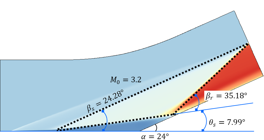
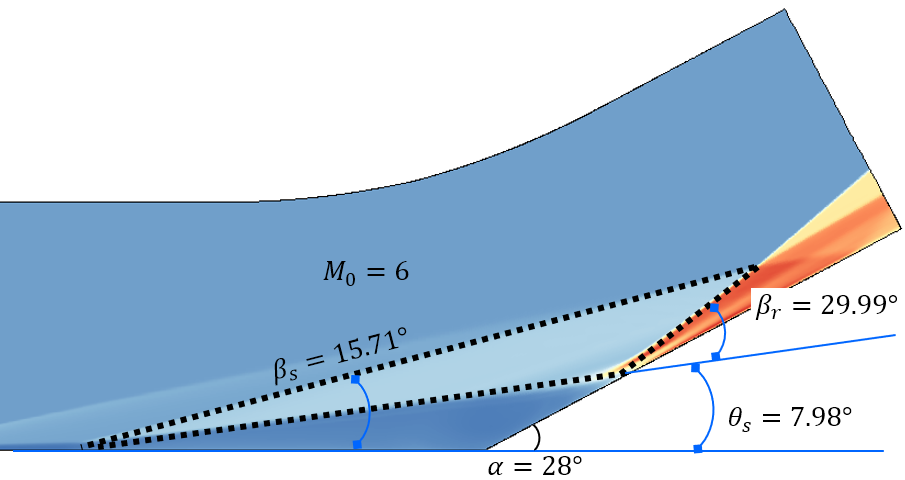
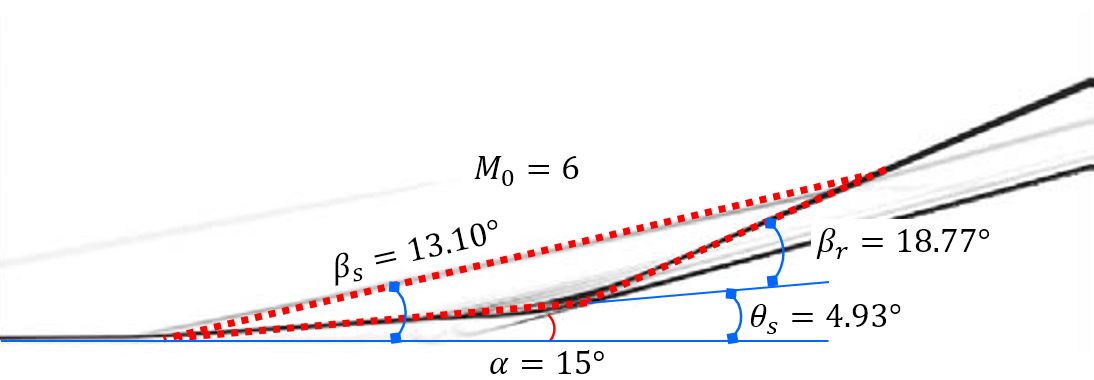
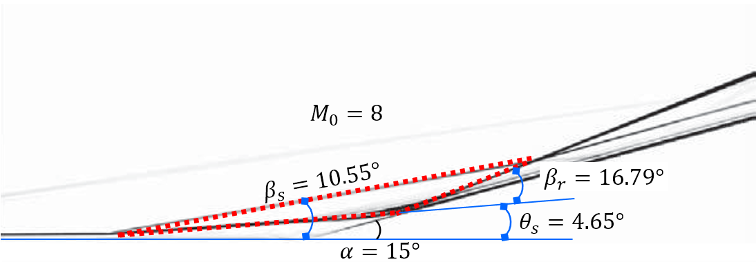
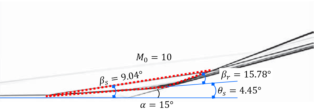
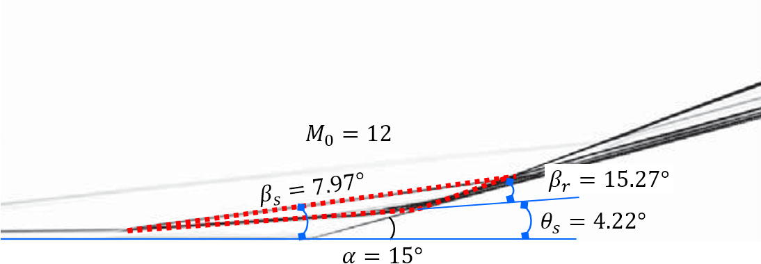


Figure 3 shows the comparison of the proposed theoretical , , and with numerical results from different researchers (our DNSs, Babinsky & Harvey (2011, pp. 318-319) and Gai & Khraibut (2019)). The theory in this paper can be observed to agree well with the flow patterns encompassing a wide range of Mach numbers and ramp angles ( varying from 3.2 to 12, varying from to ). As and increase, the pressure peak behind the reattachment shock wave, located at subsystem 2 in Figure 1 (b), increases rapidly and will be two orders of magnitude larger than the free-stream pressure . Figure 4 depicts the comparison of theoretical with that of previous works, including experimental ((Holden, 1970; Elfstrom, 1972; Delery & Coet, 1990, 1991)) and numerical (RUDY et al. (1989); Jiang & Richards (1991); Thomas et al. (1991); Vahdati et al. (1991); Mallet et al. (1991); Chalot et al. (1991); Simeonides et al. (1994); Simeonides & Haase (1995); Marini (2001); Babinsky & Harvey (2011); Gai & Khraibut (2019)) results. The theoretical is observed to agree well with all the numerical and experimental results with a varying from 3.2 to 14.1 and varying from to . Furthermore, for a large separation, as Table 1 shows, the theoretical predictions are independent of the the Reynolds number and the wall temperature , which is because the dissipation induced by shear layers can be negligible relative to shock waves, as demonstrated in Section 3. Additionally, as the maximum heat flux generated in the reattachment region can be correlated with in terms of simple power-law relations (Holden (1978)), the proposed theory can be used to estimate the quantificationally, which is vital in both supersonic and hypersonic flows.

| () | () | () | state | author | |||||
|---|---|---|---|---|---|---|---|---|---|
| theory | EXP/CFD | inviscid | |||||||
| 14.1 | 24° | 297.22 | 88.88 | L | 102.95 | 123.5 (EXP) | 58.02 | Holden | |
| 14.1 | 18° | 297.22 | 88.88 | L | 54.52 | 51.88 (EXP) | 34.23 | ||
| 9.22 | 38° | 295 | 59.44 | T | 106.08 | 93.13 (EXP) | 58.28 | Elfstrom | |
| 9.1 | 24° | 351.24 | 160 | L | 36.3 | 37.32 (CFD) | 25.48 | Gai & Khraibut | |
| 6.0 | 28° | 307 | 108.1 | L | 20.04 | 20.15 (CFD) | 15.84 | Hu et al. | |
5 Conclusion
In this work, the least action principle is used to reveal that the synergic principle of a compression ramp flow with large separation is the minimal dissipation theorem. Based on this theorem, we obtain theoretical flow patterns and the pressure peak , which agree very well with the numerical and experimental results for a wide range of Mach numbers and ramp angles . Because the maximum heat flux at the reattachment region can be correlated with in terms of simple power-laws, can be estimated quantificationally, which is vital in aerospace engineering. Furthermore, the predicted results are independent of the Reynolds number and wall temperature . The present theoretical framework has both a strict mathematical logic and a clear physical image, which are expected to be applied to other flow systems dominated by shock waves.
Acknowledgement
We are grateful to Professor You-Sheng Zhang for his helpful discussion and to Professor Xin-Liang Li for his support of the numerical simulation. This work is supported by National Key R & D Program of China (Grant No.2019YFA0405300).
References
- Babinsky & Harvey (2011) Babinsky, Holger & Harvey, John K 2011 Shock wave-boundary-layer interactions, , vol. 32. Cambridge University Press.
- Burggraf (1975) Burggraf, OR 1975 Asymptotic theory of separation and reattachment of a laminar boundary layer on a compression ramp. Tech. Rep.. OHIO STATE UNIV RESEARCH FOUNDATION COLUMBUS.
- Chalot et al. (1991) Chalot, F, Hughes, TJR, Johan, Z & Shakib, F 1991 Application of the galerkin/least-squares formulation to the analysis of hypersonic flows: I. flow over a two-dimensional ramp. In Hypersonic Flows for Reentry Problems, pp. 181–200. Springer.
- Daniels (1979) Daniels, PG 1979 Laminar boundary-layer reattachment in supersonic flow. Journal of Fluid Mechanics 90 (2), 289–303.
- Deepak et al. (2013) Deepak, NR, Gai, SL & Neely, AJ 2013 A computational investigation of laminar shock/wave boundary layer interactions. The Aeronautical Journal 117 (1187), 27–56.
- Delery & Coet (1990) Delery, J & Coet, MC 1990 Experimental investigation of shock-wave boundary-layer interaction in hypersonic flows. In Workshop on Hypersonic Flows for Reentry Problems, , vol. 3, pp. 1–22.
- Delery & Coet (1991) Delery, J & Coet, M-C 1991 Experiments on shock-wave/boundary-layer interactions produced by two-dimensional ramps and three-dimensional obstacles. In Hypersonic Flows for Reentry Problems, pp. 97–128. Springer.
- Délery et al. (1986) Délery, Jean, Marvin, John G & Reshotko, Eli 1986 Shock-wave boundary layer interactions. Tech. Rep.. ADVISORY GROUP FOR AEROSPACE RESEARCH AND DEVELOPMENT NEUILLY-SUR-SEINE (FRANCE).
- Edney (1968) Edney, Barry 1968 Anomalous heat transfer and pressure distributions on blunt bodies at hypersonic speeds in the presence of an impinging shock. Tech. Rep.. Flygtekniska Forsoksanstalten, Stockholm (Sweden).
- Elfstrom (1972) Elfstrom, GM 1972 Turbulent hypersonic flow at a wedge-compression corner. Journal of fluid Mechanics 53 (1), 113–127.
- Gai & Khraibut (2019) Gai, Sudhir L & Khraibut, Amna 2019 Hypersonic compression corner flow with large separated regions. Journal of Fluid Mechanics 877, 471–494.
- Goldenfeld (2018) Goldenfeld, Nigel 2018 Lectures on phase transitions and the renormalization group. CRC Press.
- He et al. (1988) He, Ke-Ren, Yang, D-H & Wu, Jie-Zhi 1988 The extension of minimum energy dissipation theorem and limitation of minimum entropy production principle in fluid flow (in chinese). J. Engng. Thermophys 9, 10–12.
- Helmholtz (1868) Helmholtz, H von 1868 Zur theorie der stationären ströme in reibenden flüssigkeiten. Wiss. Abh 1, 223–230.
- Holden (1978) Holden, Michael 1978 A study of flow separation in regions of shock wave-boundary layer interaction in hypersonic flow. In 11th Fluid and PlasmaDynamics Conference, p. 1169.
- Holden (1966) Holden, Michael S 1966 Experimental studies of separated flows at hypersonic speeds. ii-two-dimensional wedge separated flow studies. AIAA Journal 4 (5), 790–799.
- Holden (1970) Holden, Michael S 1970 Theoretical and experimental studies of the shock wave-boundary layer interaction on compression surfaces in hypersonic flow. Tech. Rep.. CORNELL AERONAUTICAL LAB INC BUFFALO NY.
- Hung & MacCormack (1976) Hung, CM & MacCormack, RW 1976 Numerical solutions of supersonic and hypersonic laminar compression corner flows. AIAA Journal 14 (4), 475–481.
- Jiang & Richards (1991) Jiang, Dachun & Richards, BE 1991 Hypersonic viscous flow over two-dimensional ramps. In Hypersonic Flows for Reentry Problems, pp. 228–243. Springer.
- Korolev et al. (2002) Korolev, GL, Gajjar, JSB & Ruban, AI 2002 Once again on the supersonic flow separation near a corner. Journal of Fluid Mechanics 463, 173–199.
- Landau (1937) Landau, Lev Davidovich 1937 On the theory of phase transitions. Ukr. J. Phys. 11, 19–32.
- Lewis et al. (1968) Lewis, John E, Kubota, Toshi & Lees, Lester 1968 Experimental investigation of supersonic laminar, two-dimensional boundary-layer separation in a compression corner with and without cooling. AIAA journal 6 (1), 7–14.
- Mallet et al. (1991) Mallet, M, Mantel, B, Périaux, J & Stoufflet, B 1991 Contribution to problem 3 using a galerkin least square finite element method. In Hypersonic Flows for Reentry Problems, pp. 255–267. Springer.
- Mallinson et al. (1997) Mallinson, SG, Gai, SL & Mudford, NR 1997 The interaction of a shock wave with a laminar boundary layer at a compression corner in high-enthalpy flows including real gas effects. Journal of fluid mechanics 342, 1–35.
- Marini (2001) Marini, Marco 2001 Analysis of hypersonic compression ramp laminar flows under sharp leading edge conditions. Aerospace science and technology 5 (4), 257–271.
- Neiland et al. (2008) Neiland, V Ya, Sokolov, LA & Shvedchenko, VV 2008 Temperature factor effect on the structure of the separated flow within a supersonic gas stream. Fluid Dynamics 43 (5), 706–717.
- Olejniczak & Candler (1998) Olejniczak, Joseph & Candler, Graham 1998 Computation of hypersonic shock interaction flow fields. In 7th AIAA/ASME Joint Thermophysics and Heat Transfer Conference, p. 2446.
- Prigogine (1978) Prigogine, Ilya 1978 Time, structure, and fluctuations. Science 201 (4358), 777–785.
- Rankine (1887) Rankine, PH 1887 Sur la propagation du mouvement dans les corps et spécialement dans les gaz parfaits, 2e partie. Journal de l’École Polytechnique. Paris 57, 3–97.
- Rankine (1870) Rankine, William John Macquorn 1870 Xv. on the thermodynamic theory of waves of finite longitudinal disturbance. Philosophical Transactions of the Royal Society of London (160), 277–288.
- Rayleigh (1913) Rayleigh, Lord 1913 Lxv. on the motion of a viscous fluid. The London, Edinburgh, and Dublin Philosophical Magazine and Journal of Science 26 (154), 776–786.
- Rizzetta et al. (1978) Rizzetta, DP, Burggraf, OR & Jenson, Richard 1978 Triple-deck solutions for viscous supersonic and hypersonic flow past corners. Journal of Fluid Mechanics 89 (3), 535–552.
- RUDY et al. (1989) RUDY, DAVID, THOMAS, JAMES, Kumar, Ajay, GNOFF, PETER & CHAKRAVARTHY, SUKUMAR 1989 A validation study of four navier-stokes codes for high-speed flows. In 20th Fluid Dynamics, Plasma Dynamics and Lasers Conference, p. 1838.
- Serrin (1959) Serrin, James 1959 Mathematical principles of classical fluid mechanics. In Fluid Dynamics I/Strömungsmechanik I, pp. 125–263. Springer.
- Shvedchenko (2009) Shvedchenko, Vladimir Viktorovich 2009 About the secondary separation at supersonic flow over a compression ramp. TsAGI Science Journal 40 (5).
- Simeonides & Haase (1995) Simeonides, G & Haase, W 1995 Experimental and computational investigations of hypersonic flow about compression ramps. Journal of Fluid Mechanics 283, 17–42.
- Simeonides et al. (1994) Simeonides, G, Haase, W & Manna, M 1994 Experimental, analytical, and computational methods applied to hypersonic compression ramp flows. AIAA journal 32 (2), 301–310.
- Smith & Khorrami (1991) Smith, FT & Khorrami, A Farid 1991 The interactive breakdown in supersonic ramp flow. Journal of fluid mechanics 224, 197–215.
- Thomas et al. (1991) Thomas, James L, Rudy, David H, Kumar, Ajay & Van Leer, Bram 1991 Grid-refinement study of hypersonic laminar flow over a 2-d ramp. In Hypersonic Flows for Reentry Problems, pp. 244–254. Springer.
- Vahdati et al. (1991) Vahdati, M, Morgan, K & Peraire, J 1991 The application of an adaptive upwind unstructured grid solution algorithm to the simulation of compressible laminar viscous flows over compression corners. In Hypersonic Flows for Reentry Problems, pp. 201–211. Springer.
- Wu et al. (2007) Wu, Jie-Zhi, Ma, Hui-Yang & Zhou, M-D 2007 Vorticity and vortex dynamics. Springer Science & Business Media.