Plasmonic quantum nonlinear Hall effect in noncentrosymmetric 2D materials
Abstract
We investigate an interplay between quantum geometrical effects and surface plasmons through surface plasmonic structures, based on an electron hydrodynamic theory. First we demonstrate that the quantum nonlinear Hall effect can be dramatically enhanced over a very broad range of frequency by utilizing plasmonic resonances and near-field effects of grating gates. Under the resonant condition, the enhancement becomes several orders of magnitude larger than the case without the nanostructures, while the peaks of high-harmonic plasmons expand broadly and emerge under the off-resonant condition, leading to a remarkably broad spectrum. Furthermore, we clarify a universal relation between the photocurrent induced by the Berry curvature dipole and the optical absorption, which is essential for computational material design of long-wavelength photodetectors. Next we discuss a novel mechanism of geometrical photocurrent, which originates from an anomalous force induced by oscillating magnetic fields and is described by the dipole moment of orbital magnetic moments of Bloch electrons in the momentum space. Our theory is relevant to 2D quantum materials such as layered WTe2 and twisted bilayer graphene, thereby providing a promising route toward a novel type of highly sensitive, broadband terahertz photodetectors.
Introduction.— Quantum geometry plays a crucial role in the linear/nonlinear optical responses of bulk crystals, as exemplified by natural optical activity Malashevich and Souza (2010); Orenstein and Moore (2013); Zhong et al. (2015); Ma and Pesin (2015); Hosur and Qi (2015); Zhong et al. (2016); Flicker et al. (2018); Wang et al. (2020), bulk photovoltaic effect Aversa and Sipe (1995); Sipe and Shkrebtii (2000); Nagaosa and Morimoto (2017); Ahn et al. (2020); Watanabe and Yanase (2021), and geometric photon drag Shi et al. (2021). These phenomena provide us with not only a deep insight into the band structure of crystals, but also a variety of functional optical devices, such as solar cells Tan et al. (2016); Cook et al. (2017) and infrared/terahertz photodetectors Liu et al. (2020); Isobe et al. (2020); Zhang and Fu (2021). For example, recently, the quantum nonlinear Hall (QNLH) effect Sodemann and Fu (2015) —an intrinsic low-frequency photocurrent driven by the Berry curvature dipole— is attracting much interest as a promising candidate for a broadband long-wavelength photodetector at room temperature Zhang and Fu (2021); Du et al. (2021).
Plasmonic nanostructures also provide us with another type of efficient and electrically-tunable optical devices Atwater and Polman (2010); Yao and Liu (2014); Low and Avouris (2014); Hentschel et al. (2017); Yang et al. (2022). Such a plasmonic nanodevice achieves its remarkable performance by utilizing the nonlocality and the plasmonic enhancement triggered by the nanostructures. In particular, surface plasmons inherent in two-dimensional (2D) layered systems, such as graphene, are known to have remarkably long lifetimes and electrically-tunable dispersions in the terahertz or mid-infrared region Ju et al. (2011); Basov et al. (2016); Li et al. (2017a). These properties are ideal for plasmonic devices, and thus a lot of papers have been devoted to investigating the applications such as tunable terahertz photodetectors Koppens et al. (2014); Bandurin et al. (2018a); Ryzhii et al. (2020); Zhang and Shur (2021) and broadband absorbers Ke et al. (2015); Chaudhuri et al. (2018); Huang et al. (2020).
Electron hydrodynamics, which is quickly growing into a mature field of condensed matter physics Narozhny et al. (2017); Lucas and Fong (2018); Narozhny (2019); Polini and Geim (2020); Narozhny (2022), gives us a powerful tool to describe electronic collective modes Principi et al. (2016); Gorbar et al. (2017); Zhang et al. (2018); Zhang and Vignale (2018); Svintsov (2018); Sukhachov et al. (2018); Gorbar et al. (2018); Narozhny et al. (2021); Kapralov and Svintsov (2022) and nonlocality of optical responses Raza et al. (2015); Mendoza et al. (2013); Forcella et al. (2014); Yan (2015); Sun et al. (2018a, b); Alekseev (2018); Alekseev and Alekseeva (2019); Ryzhii et al. (2020); Potashin et al. (2020); Shabbir and Leuenberger (2020); Alekseev and Alekseeva (2021); Man et al. (2021); Zhang and Shur (2021); De Luca et al. (2021); Pusep et al. (2022); Valentinis et al. (2022), Remarkable examples related with optical applications include the theory of the plasmonic instability Dyakonov and Shur (1993, 1996); Mikhailov (1998); Vicarelli et al. (2012); Tomadin and Polini (2013); Spirito et al. (2014); Torre et al. (2015); Mendl and Lucas (2018); Mendl et al. (2021); Cosme and Terças (2021); Crabb et al. (2021) and the ratchet effect Popov et al. (2011); Olbrich et al. (2011); Ivchenko and Ganichev (2011); Popov (2013); Rozhansky et al. (2015); Olbrich et al. (2016); Rupper et al. (2018); Mönch et al. (2022, 2022), both of which harness the plasma modes to realize highly efficient photovoltaic conversions. Interestingly, for the latter, the hydrodynamic signature has been observed very recently in bilayer graphene with an asymmetric dual-grating gate potential Mönch et al. (2022, 2022). As a more recent development, symmetry of crystals and quantum geometry give a new twist to the concept of electron hydrodynamics Cook and Lucas (2019); Varnavides et al. (2020a); Rao and Bradlyn (2020); Robredo et al. (2021); Rao and Bradlyn (2021); Gorbar et al. (2018); Link and Herbut (2020); Varnavides et al. (2020b); Toshio et al. (2020); Funaki and Tatara (2021); Funaki et al. (2021); Tatara (2021); Tavakol and Kim (2021); Hasdeo et al. (2021); Sano et al. (2021); Wang et al. (2021); Varnavides et al. (2022a, b); Huang and Lucas (2022); Friedman et al. (2022); Valentinis et al. (2022); Sano et al. (2022). Indeed, in the last few years, a number of papers have addressed rich and novel hydrodynamic phenomena, represented by anisotropic viscosity effects Cook and Lucas (2019); Varnavides et al. (2020a); Rao and Bradlyn (2020); Robredo et al. (2021); Rao and Bradlyn (2021). Especially for noncentrosymmetric systems, it has been revealed that the quantum geometry causes anomalous driving forces over electon fluids, leading to unique hydrodynamic phenomena such as asymmetric Poiseuille flows Toshio et al. (2020) and nonreciprocal surface plasmons Sano et al. (2021). These frameworks enable us to investigate the interplay between quantum geometry and surface plasmons in novel materials, such as topological or van der Waals (vdW) materials Hasan and Kane (2010); Stauber (2014); Basov et al. (2016); Yan and Felser (2017). These issues have not been executed so far, except for several limited problems Pellegrino et al. (2015); Principi et al. (2016); Song and Rudner (2016); Hofmann and Das Sarma (2016); Kumar et al. (2016); Gorbar et al. (2017); Zhang et al. (2018); Zhang and Vignale (2018); Lu et al. (2021); Sano et al. (2021).
In this Letter, based on an electron hydrodynamics, we develop a generic theory of geometrical photocurrent in noncentrosymmetric 2D layered systems with periodic grating gates. First we demonstrate that the QNLH effect is enhanced dramatically by plasmonic resonances and near-field effects of grating gates, which is dubbed the plasmonic QNLH effect. It features multiple sharp peaks near the plasma frequencies, and could be enhanced by several orders of magnitude over a very broad range of frequency. Furthermore, assuming more generic situations, we uncover a universal relation between the photocurrent induced by the Berry curvature dipole and the optical absorption, which is essential for computational material design of long-wavelength photodetectors. Finally we discuss another type of novel geometrical photocurrent, the magnetically-driven plasmonic photogalvanic effect. This is a spatially dispersive contribution to the total photocurrent and originates from the anomalous driving force on electron fluids, which is described by the dipole moment of orbital magnetic moments in the momentum space.
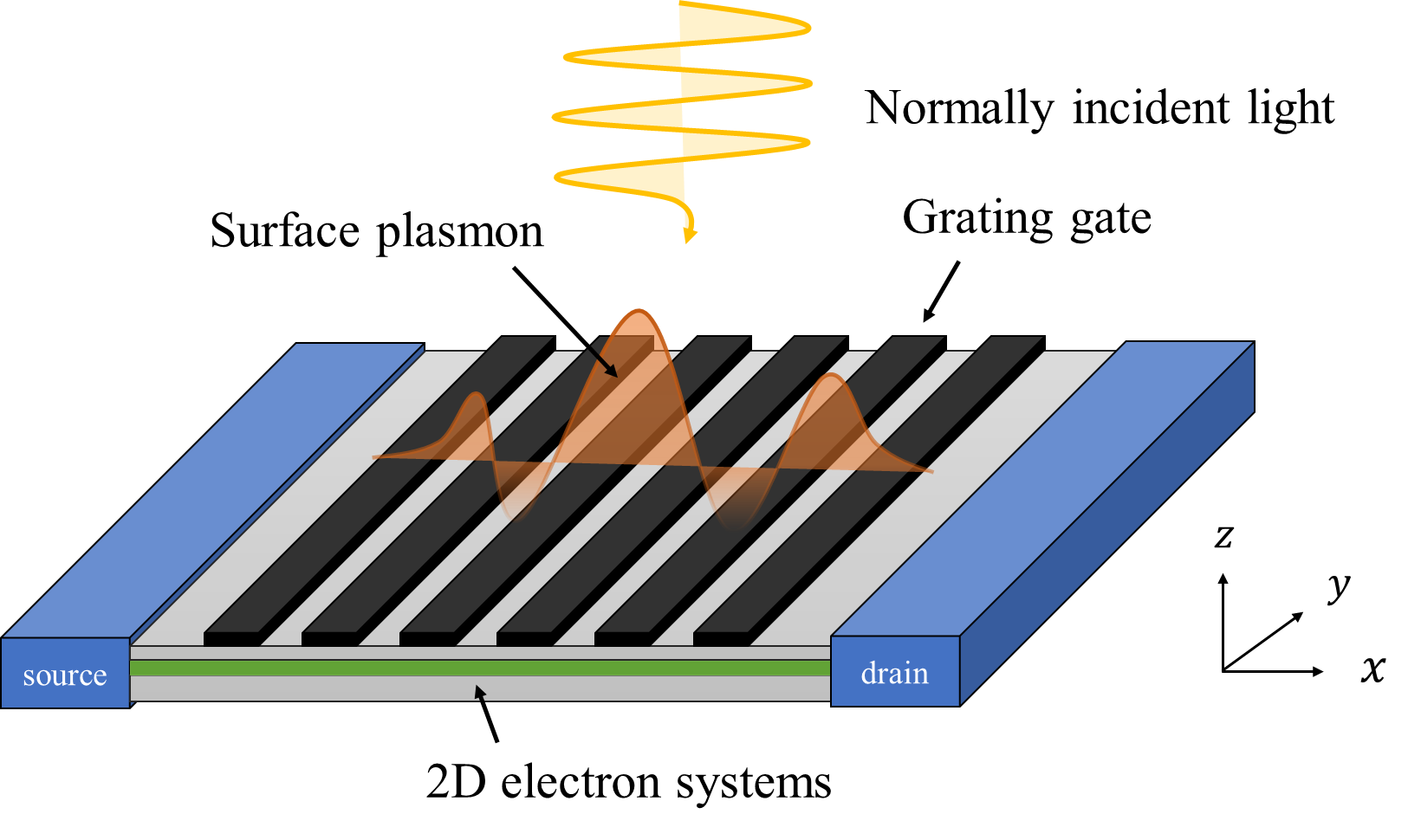
Setups.— Let us specify our model to describe noncentrosymmetric layered systems with plasmonic grating gates (see Fig. 1). We assume that the grating gate spatially modulates the normally incident light , leading to the spatially dispersive electric field in 2D electron systems Rozhansky et al. (2015); Mönch et al. (2022):
| (1) |
where the diagonal matrix is a phenomenological parameter to determine the direction of the modulated electric field Com . Especially when is finite, the Faraday’s law results in the presence of an out-of-plane magnetic field,
| (2) |
Since the grating gate strongly confines the incident light into the - plane with a fixed small wavelength, this magnetic field has non-negligible contributions especially in the low frequency limit, leading to a novel mechanism of the photovoltaic effect as discussed below.
When the gate electrode is separated from the channel by an insulator thin film with thickness and gate-to-channel capacity , the 2D electron concentration is approximately determined by the local gate-to-channel voltage : . Such an approximation is often referred to as a gradual channel approximation Shur (1987); Dyakonov and Shur (1993), which is valid for smooth perturbation with . In summary, the total electric field is given by the sum of the incident light and the field coming from the density perturbation: .
Next let us consider the dynamics of electron fluids in noncentrosymmetric crystals with time-reversal symmetry. In this paper, we focus on the hydrodynamic regime, where the rate of electron-electron scatterings exceeds that of other momentum-relaxing scatterings , and thereby the total electron momentum can be regarded as a long-lived quantity Landau and Lifshitz (1987); Narozhny et al. (2017); Lucas and Fong (2018); Narozhny (2019); Polini and Geim (2020). Under these conditions, the electron dynamics is described by an emergent hydrodynamic theory, whose form crucially depends on the symmetry of the systems Gorbar et al. (2018); Cook and Lucas (2019); Link and Herbut (2020); Rao and Bradlyn (2020); Varnavides et al. (2020a, b); Toshio et al. (2020); Funaki et al. (2021); Tavakol and Kim (2021); Robredo et al. (2021); Hasdeo et al. (2021); Sano et al. (2021); Wang et al. (2021); Rao and Bradlyn (2021); Varnavides et al. (2022a, b); Huang and Lucas (2022); Friedman et al. (2022); Valentinis et al. (2022). As also mentioned later, such a hydrodynamic behavior of electrons have been observed in transport experiments in various materials, and attracting a lot of interest in the last few years Polini and Geim (2020); Narozhny (2022).
For noncentrosymmetric electron fluids with parabolic dispersion near some valley , the formulation of electron hydrodynamics is obtained in Ref. Toshio et al. (2020); Sano et al. (2021). Under some reasonable approximations com , we can transform the hydrodynamic equations for our analysis as follows:
| (3) | ||||
where and are the density of particles and mass, is an applied static magnetic field, is the velocity field of the electron fluid, and is the pressure. The last term on the left-hand side in the first equation is first derived in Ref Sano et al. (2021), and represents a geometrical anomalous force due to oscillating magnetic fields, which is closely related with the so-called gyrotropic magnetic effect Ma and Pesin (2015); Zhong et al. (2016); Flicker et al. (2018); Wang et al. (2020). Here is a geometrical pseudovector, and defined as the dipole component of orbital magnetic moments of Bloch electrons in the momentum space:
| (4) |
where is the Fermi distribution function at the valley , is the orbital magnetic moment of the Bloch wavepackets Xiao et al. (2010), and we have introduced the notation def .
Here it is notable that the velocity field itself is not an observable quantity. We have to relate the velocity field with the observable electric current as follows Toshio et al. (2020); Sano et al. (2021):
| (5) |
where is another geometric pseudovector, which is often refered to as the Berry curvature dipole (BCD) Sodemann and Fu (2015), defined as,
| (6) |
and is a geometrical scalar coefficient,
| (7) |
is the Berry curvature of Bloch electrons in the valley Xiao et al. (2010). Here, we note that “” in Eq. (5) denotes the rotational currents, which causes several remarkable phenomena such as voriticity-induced anomalous current Toshio et al. (2020), but does not contribute to the analysis in this work. Most important is that crystal symmetry imposes strong restrictions on the geometical pseudovectors and , and thus we have to break any rotational symmetry about the -axis and reduce the number of in-plane mirror lines to be less than two for these vectors to be finite.
Plasmonic QNLH effect.— Here we demonstrate that the spatial modulation by grating gates gives rise to the plasmonic enhancement of the QNLH effect. Interestingly, Ref. Zhang and Fu (2021) suggests recently that the QNLH effect has great potential for a broadband long-wavelength photodetector with small noise-equivalent power and remarkably high intenal responsivity, which is defined as the gain per absorbed power, in a broad range of frequency. However, since its spectrum has a Lorentzian shape located at with the half width , its external responsivity, i.e. its gain per incident power, rapidly decreases as at frequencies , while the internal responsivity keeps a good value independent on the frequencies. Therefore, it is still an open problem how to improve the external responsivity of the QNLH effect at moderately high frequencies and whether its internal responsivity remains intact even in plasmonic resonances or not. In what follows, we reveal that plasmonic resonance dramatically improves the external responsivity (or the nonlinear susceptibility) by several orders of magnitude in a broad regime of frequency over .
By performing a simple second-order perturbative analysis, we can easily solve the hydrodynamic equations (LABEL:eq:hydrodynamic_eq) and obtain the total photocurrent, which can be decomposed into two components coming from different novel mechanisms as follows (for the detailed derivation and expression, see the supplemental materials):
| (8) |
where is a photocurrent originating from the BCD vector , which is understood as a plasmonic version of the so-called QNLH effect Sodemann and Fu (2015). On the other hand, is another novel type of geometrical photocurrent, which comes from several nonlinear terms in Eq. (LABEL:eq:hydrodynamic_eq), such as the inertia term . As discussed later in more detail, since is induced by an external oscillating magnetic field in Eq. (2), we will hereafter refer to this contribution as magnetically-driven plasmonic photogalvanic (MPP) effect.
Here let us consider -polarized incident light . In this case, the total photocurrent is exactly attributed only to the contribution of the QNLH term and described by a simple beautiful form
| (9) |
where is a unit vector in the -direction, is an amplification factor due to the plasmonic resonance,
| (10) |
and we have introduced two dimensionless paramters: and . Here is the plasmon frequency , and is the group velocity of the plasmon. This is one of our main results in this work, and we refer to it as the plasmonic QNLH effect. In Fig. 2 (a), we have plotted the spectrum of for various values of .
| (a) | (b) |
 |
 |
| (c) | (d) |
 |
 |
In the low-frequency limit (), the amplification factor approaches one and Eq. (9) becomes equivalent to that in Ref. Sodemann and Fu (2015), which means that the original peak of the QNLH effect at remains intact regardless of the existence of the grating gate. On the other hand, at the plasmon frequency , it features another sharp peak with a width in the resonant regime (), and the amplitude of the QNLH current is strongly enhanced by the dimensionless factor , compared to the case without grating gate. In particular, by utilizing near-field enhancement of gold grating gates, it is possible for the grating factor to be compareble to or much larger than one () Popov et al. (2015); Olbrich et al. (2016); Maß et al. (2019). This means that the QNLH current could be enhanced by several orders of magnitude under the resonant condition ().
In the discussion so far, we have focused on a specific harmonic mode with the wavenumber in Eq. (1) for simplicity. However, we note that, in general, the grating gate creates high-harmonic modulations of in-plane electric fields with the wavenumbers , , , Popov et al. (2003); Fateev et al. (2010); Olbrich et al. (2011); Ivchenko and Petrov (2014), which can be described as
| (11) |
These modulations result in multiple plasmonic resonant peaks at , , , , leading to a remarkably broadband photocurrent spectrum. In particular, since the result in Eq. (9) does not depend on the phases and the signs of , all the contribution of high-harmonic plasmons flow in the same direction, and thereby strongly enhance the total photocurrent. This is in sharp contrast to the case of the so-called ratchet effect Olbrich et al. (2011); Rozhansky et al. (2015), which is strongly depend on these parameters, and thus, each plasma mode often cancels each other. In conclusion, enhancement factor (10) is modified by high-harmonic plasmons as follows:
| (12) |
In Fig. 2 (b-d), We have plotted the spectrum of the plasmonic QNLH current (blue line), and campared it with that of the normal QNLH effect. From these figures, we find that the QNLH current is dramatically enhanced by several orders of amplitude, over a very broad range of frequency above the original frequency threshold . Similar enhancement effects due to high-harmonic plasma modes have ever been discussed in the context of terahertz light absorption Popov et al. (2003); Muravjov et al. (2010); Guo et al. (2013) and plasmonic ratchet effect Popov et al. (2015); Olbrich et al. (2016).
Universal internal responsivity.— Here, assuming more general situations, we elucidate a universal relation between the photocurrent induced by the BCD and the light absorption by 2D electron systems. First, in general, the BCD-induced photocurrent is obtained from Eq. (5) in the following form,
| (13) |
where denotes the time and space averaging over the periods. Especially for -polarized incident light, it leads to . On the other hand, the optical power absorbed by 2D electron systems can be calculated as , where is the area of our system and is the sample’s size in the -direction. In the linear order of external perturbations, the electric current is related with the velocity field as from Eq. (5), where is the equilibrium particle density. Combining these formulas, we reach the desired universal relation between and as follows:
| (14) |
This relation means that the plasmonic QNLH effect discussed above comes from the plasmonic enhancement of the total optical absorption by grating gate. As understood from the derivation, Eq. (14) will be satisfied in more generic situations beyond our 2D grating model, such as plasmonic cavities Li et al. (2017b); Hugall et al. (2018); Xiao et al. (2018); Epstein et al. (2020) or antennas Bandurin et al. (2018a); Ullah et al. (2020), as far as the frequency is low enough for interband transitions to be negligible Not . Here we note that, as easily checked from the formula, Eq. (14) does not hold for the circular photogalvanic current induced by the BCD com . This means that higher efficiency could be achieved for circularly polarized light, which is analogous to recent proposals in Ref. Onishi et al. (2022); kun Shi et al. (2022).
From Eq. (14), we can immediately obtain the internal current responsivity of the BCD-induced Hall photocurrent, which is one of the most important figures of merit quantifying the performance of THz detectors Koppens et al. (2014) and defined as the current gain per absorbed light power,
| (15) |
This is another important result in this paper. Eq. (15) states that the responsivity is entirely determined by the band structure (and the carrier density) of electron sytems, and completely independent on incident frequencies and their environment such as grating or cavity structures. Clearly, this property is very beneficial for computational material design toword terahertz-infrared photodetectors. To realize a high-performance photodetector utilizing the BCD-induced photocurrent, first we should search quantum materials with a collossal effective mass and BCD by performing ab-initio calculations or experiments, and then, improve their optical absorption by decorating or designing those promising materials with some plasmonic or cavity structures.
For the latter purpose, 2D layered materials, which are very flexible to various device designs, seem to be more advantageous than 3D bulk materials. Recent experiments Ma et al. (2019) have reported that the external voltage responsivity of bilayer WTe2 reaches a value of V/W-1 around Hz at K, which is notably large and comparable to the best values in existing rectifiers Ma et al. (2019); Auton et al. (2016). Furthermore, Ref. Zhang et al. (2022) has theoretically suggested that strained twisted bilayer graphene achieves a further large responsivity that is 20 times larger than the above values. However, since these materials work well only at low temperature, further investigations of promising materials, which show a remarkably large value of the BCD, will be needed to realize terahertz photodetectors working at room temperature.
Magnetically-driven plasmonic photogalvanic effect.— Next let us consider a novel type of photocurrent, , obtained in Eq. (8), which is regarded as a spatially dispersive correction to the total photocurrent and proportional to or . For this reason, this effect is peculiar to spatially structured systems like our grating model, and does not appear in spatially uniform cases.
As shown in detail in the supplemental materials, the MPP effect originates from an anomalous driving force induced by oscillating magnetic fields () in Eq. (LABEL:eq:hydrodynamic_eq), and thus, they are described by the geometrical pseudovector, , i.e., the dipole moment of orbital magnetic moments of Bloch electrons in the momentum space (for the detailed derivation and expression, see the supplemental materials). In particular, at plasmon frequencies, the MPP current also has a sharp peak, as in the case of the plasmonic QNLH effect, and the peak amplitude is obtained under the resonant condition () as follows neg :
| (16) | ||||
Here we have introduced and , each of which represents a circular photogalvanic effect and a linear photogalvanic effect. Focusing on its circular photogalvanic effect in the -direction, the value of MPP current is around 0.01 nA/W with typical values of parameters, , m/s, s and an estimated value of obtained in Ref. Sano et al. (2021) for strained graphene, sA/kgm, assuming the resonant case . Although this is much smaller than the measured value of QNLH current ( nA/W) in monolayer WTe2 Xu et al. (2018) around THz at 150 K, we might be able to improve the MPP current furthermore by seeking materials with a much larger value of . In such a situation, since the plasmonic term of the BCD-induced circular photocurrent is proportional to and thus vanishes at the plasmon frequency, the MPP effect will dominate the total photocurrent. This might be one of good optical probes for the geometical strctures of Bloch electrons in 2D quantum systems.
Discussion.— Here we briefly discuss possible candidates to observe the novel types of plasmonic photocurrents obtained in this work. In the past few years, many pieces of evidence for hydrodynamic electron flow have been reported in various materials, including monolayer/bilayer graphene Bandurin et al. (2016); Crossno et al. (2016); Kumar et al. (2017); Bandurin et al. (2018b); Sulpizio et al. (2019); Berdyugin et al. (2019), GaAs quantum wells Molenkamp and de Jong (1994); de Jong and Molenkamp (1995); Braem et al. (2018); Gusev et al. (2018a, b); Levin et al. (2018), 2D monovalent layered metal PdCoO2 Moll et al. (2016), Weyl semimetal WP2 Gooth et al. (2018), and WTe2 Vool et al. (2021); Choi et al. (2022); Aharon-Steinberg et al. (2022). Among these materials, promising candidates for our work are graphene with some deformation and layered transition metal dichalcogenide WTe2. These materials have crystal symmetries low enough to exhibit intriguing optical phenomena, such as the QNLH effect Sodemann and Fu (2015), which is required for the geometrical pseudovectors and to be finite. As a matter of fact, the QNLH effect itself has already been observed in layered WTe2 Xu et al. (2018); Ma et al. (2019); Wang and Qian (2019); Kang et al. (2019) and artificially corrugated bilayer graphene Ho et al. (2021). In particular, bilayer WTe2 is reported to show remarkably high responsivity Ma et al. (2019) as already mentioned, and further dramatic enhancement of the BCD is suggested by twisting the two layers in Ref. He and Weng (2021).
Another possible candidate is (110) quantum well in GaAs, since it also has crystal symmetries low enough to show the QNLH effect Moore and Orenstein (2010); Ganichev et al. (2001); Diehl et al. (2007); Olbrich et al. (2009) and another type of GaAs quantum well has already shown various hydrodynamic signatures Molenkamp and de Jong (1994); de Jong and Molenkamp (1995); Braem et al. (2018); Gusev et al. (2018a, b); Levin et al. (2018). Furthermore, twisted bilayer graphene, a novel layered system attracting great interest recently, might also be a candidate for our work, since this material is theoretically suggested to realize the hydrodynamic regime Zarenia et al. (2020) and to show a remarkably high responsivity of the QNLH effect Zhang et al. (2022).
Finally, we give a brief discussion about the viscosity effect on our results com . In the context of electron hydrodynamics, viscosity is regarded as a key ingredient to characterize electron dynamics in the hydrodynamic regime. Actually, a lot of recent experiments have ever been devoted to measurements of the signature of viscosity in nonlocal transport phenomena Bandurin et al. (2016); Moll et al. (2016); Gooth et al. (2018); Levin et al. (2018); Gusev et al. (2018b, a); Berdyugin et al. (2019). By turning on viscosity term phenomenologically in Eq. (LABEL:eq:hydrodynamic_eq), we find that the width of plasmonic peaks in Eq. (9) is modified from to , where and are the kinetic viscosity and the bulk viscosity. This means that, for typical values of parameters and Bandurin et al. (2016), viscosity causes non-negligible contributions to the plasmon lifetime when the cycle length becomes m-order or less. Consequently, it might be possible to optically probe mysterious aspects of strongly correlated electron systems such as twisted bilayer graphene Cao et al. (2020); González and Stauber (2020); Cha et al. (2021); Das Sarma and Wu (2022), through the peculiar temperature dependence of plasmon lifetime, since the electron viscosity behaves as in Fermi liquids Qian and Vignale (2005); Alekseev (2016); Gooth et al. (2018), while in typical non-Fermi liquids Davison et al. (2014); Gooth et al. (2018); Narozhny (2019); Kovtun et al. (2005).
Conclusion.— In summary, based on an electron hydrodynamic theory, we have formulated plasmonically-driven geometrical photocurrents in nocentrosymmetric 2D layered systems with periodic grating gates. Our framework can be generalized to various types of problems in plasmonics, such as plasmonic responses of 1D vdW materials Freitag et al. (2013); Guo et al. (2022) and gate-controlled optical activity Kim et al. (2017), plasmon-to-current converters Popov (2013); Shokri Kojori et al. (2016). This provide us with a new way to investigate the role of quantum geometry in plasmonics, leading to a promising route toward a novel type of highly sensitive, broadband and electrically-controllable terahertz plasmonic devices.
Acknowledgments.— We would like to express our special thanks to Hikaru Watanabe and Koichiro Tanaka for useful comments. We are also grateful to Gen Tatara, Hiroshi Funaki, Ryotaro Sano, and Akito Daido for valuable discussions. This work is partly supported by JSPS KAKENHI (Grants JP20J22612, JP18H01140 and JP19H01838).
References
- Malashevich and Souza (2010) A. Malashevich and I. Souza, Phys. Rev. B 82, 245118 (2010).
- Orenstein and Moore (2013) J. Orenstein and J. E. Moore, Phys. Rev. B 87, 165110 (2013).
- Zhong et al. (2015) S. Zhong, J. Orenstein, and J. E. Moore, Phys. Rev. Lett. 115, 117403 (2015).
- Ma and Pesin (2015) J. Ma and D. A. Pesin, Phys. Rev. B 92, 235205 (2015).
- Hosur and Qi (2015) P. Hosur and X.-L. Qi, Phys. Rev. B 91, 081106 (2015).
- Zhong et al. (2016) S. Zhong, J. E. Moore, and I. Souza, Phys. Rev. Lett. 116, 077201 (2016).
- Flicker et al. (2018) F. Flicker, F. de Juan, B. Bradlyn, T. Morimoto, M. G. Vergniory, and A. G. Grushin, Phys. Rev. B 98, 155145 (2018).
- Wang et al. (2020) Y.-Q. Wang, T. Morimoto, and J. E. Moore, Phys. Rev. B 101, 174419 (2020).
- Aversa and Sipe (1995) C. Aversa and J. E. Sipe, Phys. Rev. B 52, 14636 (1995).
- Sipe and Shkrebtii (2000) J. E. Sipe and A. I. Shkrebtii, Phys. Rev. B 61, 5337 (2000).
- Nagaosa and Morimoto (2017) N. Nagaosa and T. Morimoto, Advanced Materials 29, 1603345 (2017), https://onlinelibrary.wiley.com/doi/pdf/10.1002/adma.201603345 .
- Ahn et al. (2020) J. Ahn, G.-Y. Guo, and N. Nagaosa, Phys. Rev. X 10, 041041 (2020).
- Watanabe and Yanase (2021) H. Watanabe and Y. Yanase, Phys. Rev. X 11, 011001 (2021).
- Shi et al. (2021) L.-k. Shi, D. Zhang, K. Chang, and J. C. W. Song, Phys. Rev. Lett. 126, 197402 (2021).
- Tan et al. (2016) L. Z. Tan, F. Zheng, S. M. Young, F. Wang, S. Liu, and A. M. Rappe, npj Computational Materials 2, 16026 (2016).
- Cook et al. (2017) A. M. Cook, B. M. Fregoso, F. de Juan, S. Coh, and J. E. Moore, Nature Communications 8, 14176 (2017).
- Liu et al. (2020) J. Liu, F. Xia, D. Xiao, F. J. García de Abajo, and D. Sun, Nature Materials 19, 830 (2020).
- Isobe et al. (2020) H. Isobe, S.-Y. Xu, and L. Fu, Science Advances 6, eaay2497 (2020), https://www.science.org/doi/pdf/10.1126/sciadv.aay2497 .
- Zhang and Fu (2021) Y. Zhang and L. Fu, Proceedings of the National Academy of Sciences 118, e2100736118 (2021), https://www.pnas.org/doi/pdf/10.1073/pnas.2100736118 .
- Sodemann and Fu (2015) I. Sodemann and L. Fu, Phys. Rev. Lett. 115, 216806 (2015).
- Du et al. (2021) Z. Z. Du, H.-Z. Lu, and X. C. Xie, Nature Reviews Physics 3, 744 (2021).
- Atwater and Polman (2010) H. A. Atwater and A. Polman, Nature Materials 9, 205 (2010).
- Yao and Liu (2014) K. Yao and Y. Liu, Nanotechnology Reviews 3, 177 (2014).
- Low and Avouris (2014) T. Low and P. Avouris, ACS Nano 8, 1086 (2014).
- Hentschel et al. (2017) M. Hentschel, M. Schäferling, X. Duan, H. Giessen, and N. Liu, Science Advances 3, e1602735 (2017), https://www.science.org/doi/pdf/10.1126/sciadv.1602735 .
- Yang et al. (2022) W. Yang, Q. Liu, H. Wang, Y. Chen, R. Yang, S. Xia, Y. Luo, L. Deng, J. Qin, H. Duan, and L. Bi, Nature Communications 13, 1719 (2022).
- Ju et al. (2011) L. Ju, B. Geng, J. Horng, C. Girit, M. Martin, Z. Hao, H. A. Bechtel, X. Liang, A. Zettl, Y. R. Shen, and F. Wang, Nature Nanotechnology 6, 630 (2011).
- Basov et al. (2016) D. N. Basov, M. M. Fogler, and F. J. G. de Abajo, Science 354, aag1992 (2016), https://www.science.org/doi/pdf/10.1126/science.aag1992 .
- Li et al. (2017a) Y. Li, Z. Li, C. Chi, H. Shan, L. Zheng, and Z. Fang, Advanced Science 4, 1600430 (2017a), https://onlinelibrary.wiley.com/doi/pdf/10.1002/advs.201600430 .
- Koppens et al. (2014) F. H. L. Koppens, T. Mueller, P. Avouris, A. C. Ferrari, M. S. Vitiello, and M. Polini, Nature Nanotechnology 9, 780 (2014).
- Bandurin et al. (2018a) D. A. Bandurin, D. Svintsov, I. Gayduchenko, S. G. Xu, A. Principi, M. Moskotin, I. Tretyakov, D. Yagodkin, S. Zhukov, T. Taniguchi, K. Watanabe, I. V. Grigorieva, M. Polini, G. N. Goltsman, A. K. Geim, and G. Fedorov, Nature Communications 9, 5392 (2018a).
- Ryzhii et al. (2020) V. Ryzhii, T. Otsuji, and M. Shur, Applied Physics Letters 116, 140501 (2020), https://doi.org/10.1063/1.5140712 .
- Zhang and Shur (2021) Y. Zhang and M. S. Shur, Journal of Applied Physics 129, 053102 (2021), https://doi.org/10.1063/5.0038775 .
- Ke et al. (2015) S. Ke, B. Wang, and P. Lu, in 2015 IEEE MTT-S International Microwave Workshop Series on Advanced Materials and Processes for RF and THz Applications (IMWS-AMP) (2015) pp. 1–1.
- Chaudhuri et al. (2018) K. Chaudhuri, M. Alhabeb, Z. Wang, V. M. Shalaev, Y. Gogotsi, and A. Boltasseva, ACS Photonics 5, 1115 (2018).
- Huang et al. (2020) J. Huang, J. Li, Y. Yang, J. Li, J. Li, Y. Zhang, and J. Yao, Opt. Express 28, 17832 (2020).
- Narozhny et al. (2017) B. N. Narozhny, I. V. Gornyi, A. D. Mirlin, and J. Schmalian, Annalen der Physik 529, 1700043 (2017), https://onlinelibrary.wiley.com/doi/pdf/10.1002/andp.201700043 .
- Lucas and Fong (2018) A. Lucas and K. C. Fong, Journal of Physics: Condensed Matter 30, 053001 (2018).
- Narozhny (2019) B. N. Narozhny, Annals of Physics 411, 167979 (2019).
- Polini and Geim (2020) M. Polini and A. K. Geim, Physics Today 73, 28 (2020), https://doi.org/10.1063/PT.3.4497 .
- Narozhny (2022) B. N. Narozhny, La Rivista del Nuovo Cimento (2022), 10.1007/s40766-022-00036-z.
- Principi et al. (2016) A. Principi, M. I. Katsnelson, and G. Vignale, Phys. Rev. Lett. 117, 196803 (2016).
- Gorbar et al. (2017) E. V. Gorbar, V. A. Miransky, I. A. Shovkovy, and P. O. Sukhachov, Phys. Rev. Lett. 118, 127601 (2017).
- Zhang et al. (2018) Y. Zhang, B. Guo, F. Zhai, and W. Jiang, Phys. Rev. B 97, 115455 (2018).
- Zhang and Vignale (2018) S. S.-L. Zhang and G. Vignale, Phys. Rev. B 97, 224408 (2018).
- Svintsov (2018) D. Svintsov, Phys. Rev. B 97, 121405 (2018).
- Sukhachov et al. (2018) P. O. Sukhachov, E. V. Gorbar, I. A. Shovkovy, and V. A. Miransky, Journal of Physics: Condensed Matter 30, 275601 (2018).
- Gorbar et al. (2018) E. V. Gorbar, V. A. Miransky, I. A. Shovkovy, and P. O. Sukhachov, Phys. Rev. B 97, 121105 (2018).
- Narozhny et al. (2021) B. N. Narozhny, I. V. Gornyi, and M. Titov, Phys. Rev. B 103, 115402 (2021).
- Kapralov and Svintsov (2022) K. Kapralov and D. Svintsov, “Ballistic-to-hydrodynamic transition and collective modes for two-dimensional electron systems in magnetic field,” (2022), arXiv:2203.04479 .
- Raza et al. (2015) S. Raza, S. I. Bozhevolnyi, M. Wubs, and N. A. Mortensen, Journal of Physics: Condensed Matter 27, 183204 (2015).
- Mendoza et al. (2013) M. Mendoza, H. J. Herrmann, and S. Succi, Scientific Reports 3, 1052 (2013).
- Forcella et al. (2014) D. Forcella, J. Zaanen, D. Valentinis, and D. van der Marel, Phys. Rev. B 90, 035143 (2014).
- Yan (2015) W. Yan, Phys. Rev. B 91, 115416 (2015).
- Sun et al. (2018a) Z. Sun, D. N. Basov, and M. M. Fogler, Phys. Rev. B 97, 075432 (2018a).
- Sun et al. (2018b) Z. Sun, D. N. Basov, and M. M. Fogler, Proceedings of the National Academy of Sciences 115, 3285 (2018b), https://www.pnas.org/content/115/13/3285.full.pdf .
- Alekseev (2018) P. S. Alekseev, Phys. Rev. B 98, 165440 (2018).
- Alekseev and Alekseeva (2019) P. S. Alekseev and A. P. Alekseeva, Phys. Rev. Lett. 123, 236801 (2019).
- Potashin et al. (2020) S. O. Potashin, V. Y. Kachorovskii, and M. S. Shur, Phys. Rev. B 102, 085402 (2020).
- Shabbir and Leuenberger (2020) M. W. Shabbir and M. N. Leuenberger, Scientific Reports 10, 17540 (2020).
- Alekseev and Alekseeva (2021) P. S. Alekseev and A. P. Alekseeva, “Microwave-induced resistance oscillations in highly viscous electron fluid,” (2021), arXiv:2105.01035 .
- Man et al. (2021) L. F. Man, W. Xu, Y. M. Xiao, H. Wen, L. Ding, B. Van Duppen, and F. M. Peeters, Phys. Rev. B 104, 125420 (2021).
- De Luca et al. (2021) F. De Luca, M. Ortolani, and C. Ciracì, Phys. Rev. B 103, 115305 (2021).
- Pusep et al. (2022) Y. A. Pusep, M. D. Teodoro, V. Laurindo, E. R. Cardozo de Oliveira, G. M. Gusev, and A. K. Bakarov, Phys. Rev. Lett. 128, 136801 (2022).
- Valentinis et al. (2022) D. Valentinis, G. Baker, D. A. Bonn, and J. Schmalian, “Kinetic theory of the non-local electrodynamic response in anisotropic metals: skin effect in 2d systems,” (2022), arXiv:2204.13344 .
- Dyakonov and Shur (1993) M. Dyakonov and M. Shur, Phys. Rev. Lett. 71, 2465 (1993).
- Dyakonov and Shur (1996) M. Dyakonov and M. Shur, IEEE Transactions on Electron Devices 43, 380 (1996).
- Mikhailov (1998) S. A. Mikhailov, Phys. Rev. B 58, 1517 (1998).
- Vicarelli et al. (2012) L. Vicarelli, M. S. Vitiello, D. Coquillat, A. Lombardo, A. C. Ferrari, W. Knap, M. Polini, V. Pellegrini, and A. Tredicucci, Nature Materials 11, 865 (2012).
- Tomadin and Polini (2013) A. Tomadin and M. Polini, Phys. Rev. B 88, 205426 (2013).
- Spirito et al. (2014) D. Spirito, D. Coquillat, S. L. De Bonis, A. Lombardo, M. Bruna, A. C. Ferrari, V. Pellegrini, A. Tredicucci, W. Knap, and M. S. Vitiello, Applied Physics Letters 104, 061111 (2014), https://doi.org/10.1063/1.4864082 .
- Torre et al. (2015) I. Torre, A. Tomadin, R. Krahne, V. Pellegrini, and M. Polini, Phys. Rev. B 91, 081402 (2015).
- Mendl and Lucas (2018) C. B. Mendl and A. Lucas, Applied Physics Letters 112, 124101 (2018), https://doi.org/10.1063/1.5022187 .
- Mendl et al. (2021) C. B. Mendl, M. Polini, and A. Lucas, Applied Physics Letters 118, 013105 (2021), https://doi.org/10.1063/5.0030869 .
- Cosme and Terças (2021) P. Cosme and H. Terças, Applied Physics Letters 118, 131109 (2021), https://doi.org/10.1063/5.0045444 .
- Crabb et al. (2021) J. Crabb, X. Cantos-Roman, J. M. Jornet, and G. R. Aizin, Phys. Rev. B 104, 155440 (2021).
- Popov et al. (2011) V. V. Popov, D. V. Fateev, T. Otsuji, Y. M. Meziani, D. Coquillat, and W. Knap, Applied Physics Letters 99, 243504 (2011), https://doi.org/10.1063/1.3670321 .
- Olbrich et al. (2011) P. Olbrich, J. Karch, E. L. Ivchenko, J. Kamann, B. März, M. Fehrenbacher, D. Weiss, and S. D. Ganichev, Phys. Rev. B 83, 165320 (2011).
- Ivchenko and Ganichev (2011) E. L. Ivchenko and S. D. Ganichev, JETP Letters 93, 673 (2011).
- Popov (2013) V. V. Popov, Applied Physics Letters 102, 253504 (2013), https://doi.org/10.1063/1.4811706 .
- Rozhansky et al. (2015) I. V. Rozhansky, V. Y. Kachorovskii, and M. S. Shur, Phys. Rev. Lett. 114, 246601 (2015).
- Olbrich et al. (2016) P. Olbrich, J. Kamann, M. König, J. Munzert, L. Tutsch, J. Eroms, D. Weiss, M.-H. Liu, L. E. Golub, E. L. Ivchenko, V. V. Popov, D. V. Fateev, K. V. Mashinsky, F. Fromm, T. Seyller, and S. D. Ganichev, Phys. Rev. B 93, 075422 (2016).
- Rupper et al. (2018) G. Rupper, S. Rudin, and M. S. Shur, Phys. Rev. Applied 9, 064007 (2018).
- Mönch et al. (2022) E. Mönch, S. O. Potashin, K. Lindner, I. Yahniuk, L. E. Golub, V. Y. Kachorovskii, V. V. Bel’kov, R. Huber, K. Watanabe, T. Taniguchi, J. Eroms, D. Weiss, and S. D. Ganichev, Phys. Rev. B 105, 045404 (2022).
- Mönch et al. (2022) E. Mönch, S. O. Potashin, K. Lindner, I. Yahniuk, L. E. Golub, V. Y. Kachorovskii, V. V. Bel’kov, R. Huber, K. Watanabe, T. Taniguchi, J. Eroms, D. Weiss, and S. D. Ganichev, “Cyclotron- and magnetoplasmon resonances in bilayer graphene ratchets,” (2022), arXiv:2208.08299 .
- Cook and Lucas (2019) C. Q. Cook and A. Lucas, Phys. Rev. B 99, 235148 (2019).
- Varnavides et al. (2020a) G. Varnavides, A. S. Jermyn, P. Anikeeva, C. Felser, and P. Narang, Nature Communications 11, 4710 (2020a).
- Rao and Bradlyn (2020) P. Rao and B. Bradlyn, Phys. Rev. X 10, 021005 (2020).
- Robredo et al. (2021) I. n. Robredo, P. Rao, F. de Juan, A. Bergara, J. L. Mañes, A. Cortijo, M. G. Vergniory, and B. Bradlyn, Phys. Rev. Research 3, L032068 (2021).
- Rao and Bradlyn (2021) P. Rao and B. Bradlyn, “Resolving hall and dissipative viscosity ambiguities via boundary effects,” (2021), arXiv:2112.04545 .
- Link and Herbut (2020) J. M. Link and I. F. Herbut, Phys. Rev. B 101, 125128 (2020).
- Varnavides et al. (2020b) G. Varnavides, A. S. Jermyn, P. Anikeeva, C. Felser, and P. Narang, “Generalized electron hydrodynamics, vorticity coupling, and hall viscosity in crystals,” (2020b), arXiv:2002.08976 .
- Toshio et al. (2020) R. Toshio, K. Takasan, and N. Kawakami, Phys. Rev. Research 2, 032021 (2020).
- Funaki and Tatara (2021) H. Funaki and G. Tatara, Phys. Rev. Research 3, 023160 (2021).
- Funaki et al. (2021) H. Funaki, R. Toshio, and G. Tatara, Phys. Rev. Research 3, 033075 (2021).
- Tatara (2021) G. Tatara, Phys. Rev. B 104, 184414 (2021).
- Tavakol and Kim (2021) O. Tavakol and Y. B. Kim, Phys. Rev. Research 3, 013290 (2021).
- Hasdeo et al. (2021) E. H. Hasdeo, J. Ekström, E. G. Idrisov, and T. L. Schmidt, Phys. Rev. B 103, 125106 (2021).
- Sano et al. (2021) R. Sano, R. Toshio, and N. Kawakami, Phys. Rev. B 104, L241106 (2021).
- Wang et al. (2021) Y. Wang, G. Varnavides, P. Anikeeva, J. Gooth, C. Felser, and P. Narang, “Generalized design principles for hydrodynamic electron transport in anisotropic metals,” (2021), arXiv:2109.00550 .
- Varnavides et al. (2022a) G. Varnavides, A. S. Jermyn, P. Anikeeva, and P. Narang, “Probing carrier interactions using electron hydrodynamics,” (2022a), arXiv:2204.06004 .
- Varnavides et al. (2022b) G. Varnavides, Y. Wang, P. J. W. Moll, P. Anikeeva, and P. Narang, Phys. Rev. Materials 6, 045002 (2022b).
- Huang and Lucas (2022) X. Huang and A. Lucas, Journal of High Energy Physics 2022, 82 (2022).
- Friedman et al. (2022) A. J. Friedman, C. Q. Cook, and A. Lucas, “Hydrodynamics with triangular point group,” (2022), arXiv:2202.08269 .
- Sano et al. (2022) R. Sano, D. Oue, and M. Matsuo, “Valley hydrodynamics in gapped graphene,” (2022), arXiv:2204.02409 .
- Hasan and Kane (2010) M. Z. Hasan and C. L. Kane, Rev. Mod. Phys. 82, 3045 (2010).
- Stauber (2014) T. Stauber, Journal of Physics: Condensed Matter 26, 123201 (2014).
- Yan and Felser (2017) B. Yan and C. Felser, Annual Review of Condensed Matter Physics 8, 337 (2017), https://doi.org/10.1146/annurev-conmatphys-031016-025458 .
- Pellegrino et al. (2015) F. M. D. Pellegrino, M. I. Katsnelson, and M. Polini, Phys. Rev. B 92, 201407 (2015).
- Song and Rudner (2016) J. C. W. Song and M. S. Rudner, Proceedings of the National Academy of Sciences 113, 4658 (2016), https://www.pnas.org/doi/pdf/10.1073/pnas.1519086113 .
- Hofmann and Das Sarma (2016) J. Hofmann and S. Das Sarma, Phys. Rev. B 93, 241402 (2016).
- Kumar et al. (2016) A. Kumar, A. Nemilentsau, K. H. Fung, G. Hanson, N. X. Fang, and T. Low, Phys. Rev. B 93, 041413 (2016).
- Lu et al. (2021) X. Lu, D. K. Mukherjee, and M. O. Goerbig, Phys. Rev. B 104, 155103 (2021).
- (114) Although here we have neglected the high-harmonic modulations Popov et al. (2003); Ivchenko and Petrov (2014); Popov et al. (2015) for simplicity, we will give a consideration on them in the followings. As also noted in Ref. Rozhansky et al. (2015), the field amplitude should be smaller than the amplitude of the incident field due to the screening by the gates in reality. Moreover, in general, the grating parameter strongly depends on frequencies Popov et al. (2015); Olbrich et al. (2016). Nevertheless, we believe that our simplified model captures the key physics of the problem and is sufficient for clarifying the interplay between plasmonic nanostructures and quantum geometrical effects.
- Shur (1987) M. Shur, GaAs Devices and Circuits (Plenum Press, New York, 1987).
- Landau and Lifshitz (1987) L. D. Landau and E. M. Lifshitz, Course of Theoretical Physics: Fluid Mechanics 2nd Edition (Pergamon, New York, 1987).
- (117) For the detail, please see the Supplemental Materials.
- Xiao et al. (2010) D. Xiao, M.-C. Chang, and Q. Niu, Rev. Mod. Phys. 82, 1959 (2010).
- (119) Our definition of is defferent from the one in Ref. Sano et al. (2021) by a constant factor .
- Popov et al. (2015) V. V. Popov, D. V. Fateev, E. L. Ivchenko, and S. D. Ganichev, Phys. Rev. B 91, 235436 (2015).
- Maß et al. (2019) T. W. W. Maß, V. H. Nguyen, U. Schnakenberg, and T. Taubner, Opt. Express 27, 10524 (2019).
- Popov et al. (2003) V. V. Popov, O. V. Polischuk, T. V. Teperik, X. G. Peralta, S. J. Allen, N. J. M. Horing, and M. C. Wanke, Journal of Applied Physics 94, 3556 (2003), https://doi.org/10.1063/1.1599051 .
- Fateev et al. (2010) D. V. Fateev, V. V. Popov, and M. S. Shur, Semiconductors 44, 1406 (2010).
- Ivchenko and Petrov (2014) E. L. Ivchenko and M. I. Petrov, Physics of the Solid State 56, 1833 (2014).
- Muravjov et al. (2010) A. V. Muravjov, D. B. Veksler, V. V. Popov, O. V. Polischuk, N. Pala, X. Hu, R. Gaska, H. Saxena, R. E. Peale, and M. S. Shur, Applied Physics Letters 96, 042105 (2010), https://doi.org/10.1063/1.3292019 .
- Guo et al. (2013) N. Guo, W.-D. Hu, X.-S. Chen, L. Wang, and W. Lu, Opt Express 21, 1606 (2013).
- Li et al. (2017b) K. Li, J. M. Fitzgerald, X. Xiao, J. D. Caldwell, C. Zhang, S. A. Maier, X. Li, and V. Giannini, ACS Omega 2, 3640 (2017b).
- Hugall et al. (2018) J. T. Hugall, A. Singh, and N. F. van Hulst, ACS Photonics 5, 43 (2018).
- Xiao et al. (2018) X. Xiao, X. Li, J. D. Caldwell, S. A. Maier, and V. Giannini, Applied Materials Today 12, 283 (2018).
- Epstein et al. (2020) I. Epstein, D. Alcaraz, Z. Huang, V.-V. Pusapati, J.-P. Hugonin, A. Kumar, X. M. Deputy, T. Khodkov, T. G. Rappoport, J.-Y. Hong, N. M. R. Peres, J. Kong, D. R. Smith, and F. H. L. Koppens, Science 368, 1219 (2020), https://www.science.org/doi/pdf/10.1126/science.abb1570 .
- Ullah et al. (2020) Z. Ullah, G. Witjaksono, I. Nawi, N. Tansu, M. Irfan Khattak, and M. Junaid, Sensors 20 (2020), 10.3390/s20051401.
- (132) In the case of -polarized incident light, Hall currents induced by the oscillating magnetic field, which causes spatially dispersive terms such as , slightly breaks this relation. Furthermore, since we use the fact that the particle density is spatially uniform in equilibrium to take it outside of , this relation will break in the case where strong static built-in fields is applied on the 2D electron systems by periodic doping gate as investigated in Ref. Olbrich et al. (2011); Rozhansky et al. (2015).
- Onishi et al. (2022) Y. Onishi, H. Watanabe, T. Morimoto, and N. Nagaosa, “Photovoltaic effect in noncentrosymmetric material without optical absorption,” (2022), arXiv:2204.12727 .
- kun Shi et al. (2022) L. kun Shi, O. Matsyshyn, J. C. W. Song, and I. S. Villadiego, “The berry dipole photovoltaic demon and the thermodynamics of photo-current generation within the optical gap of metals,” (2022), arXiv:2207.03496 .
- Ma et al. (2019) Q. Ma, S.-Y. Xu, H. Shen, D. MacNeill, V. Fatemi, T.-R. Chang, A. M. Mier Valdivia, S. Wu, Z. Du, C.-H. Hsu, S. Fang, Q. D. Gibson, K. Watanabe, T. Taniguchi, R. J. Cava, E. Kaxiras, H.-Z. Lu, H. Lin, L. Fu, N. Gedik, and P. Jarillo-Herrero, Nature 565, 337 (2019).
- Auton et al. (2016) G. Auton, J. Zhang, R. K. Kumar, H. Wang, X. Zhang, Q. Wang, E. Hill, and A. Song, Nature Communications 7, 11670 (2016).
- Zhang et al. (2022) C.-P. Zhang, J. Xiao, B. T. Zhou, J.-X. Hu, Y.-M. Xie, B. Yan, and K. T. Law, Phys. Rev. B 106, L041111 (2022).
- (138) Here we have neglected the term proportional to geometrical scalar for simplicity, since it is a higher-order spatially disperive term, which is proportional to , and thus much smaller than other terms for typical values of .
- Xu et al. (2018) S.-Y. Xu, Q. Ma, H. Shen, V. Fatemi, S. Wu, T.-R. Chang, G. Chang, A. M. M. Valdivia, C.-K. Chan, Q. D. Gibson, J. Zhou, Z. Liu, K. Watanabe, T. Taniguchi, H. Lin, R. J. Cava, L. Fu, N. Gedik, and P. Jarillo-Herrero, Nature Physics 14, 900 (2018).
- Bandurin et al. (2016) D. A. Bandurin, I. Torre, R. K. Kumar, M. Ben Shalom, A. Tomadin, A. Principi, G. H. Auton, E. Khestanova, K. S. Novoselov, I. V. Grigorieva, L. A. Ponomarenko, A. K. Geim, and M. Polini, Science 351, 1055 (2016), http://science.sciencemag.org/content/351/6277/1055.full.pdf .
- Crossno et al. (2016) J. Crossno, J. K. Shi, K. Wang, X. Liu, A. Harzheim, A. Lucas, S. Sachdev, P. Kim, T. Taniguchi, K. Watanabe, T. A. Ohki, and K. C. Fong, Science 351, 1058 (2016), https://science.sciencemag.org/content/351/6277/1058.full.pdf .
- Kumar et al. (2017) R. K. Kumar, D. Bandurin, F. Pellegrino, Y. Cao, A. Principi, H. Guo, G. Auton, M. B. Shalom, L. A. Ponomarenko, G. Falkovich, et al., Nature Physics 13, 1182 (2017).
- Bandurin et al. (2018b) D. A. Bandurin, A. V. Shytov, L. S. Levitov, R. K. Kumar, A. I. Berdyugin, M. Ben Shalom, I. V. Grigorieva, A. K. Geim, and G. Falkovich, Nature Communications 9, 4533 (2018b).
- Sulpizio et al. (2019) J. A. Sulpizio, L. Ella, A. Rozen, J. Birkbeck, D. J. Perello, D. Dutta, M. Ben-Shalom, T. Taniguchi, K. Watanabe, T. Holder, R. Queiroz, A. Principi, A. Stern, T. Scaffidi, A. K. Geim, and S. Ilani, Nature 576, 75 (2019).
- Berdyugin et al. (2019) A. I. Berdyugin, S. G. Xu, F. M. D. Pellegrino, R. Krishna Kumar, A. Principi, I. Torre, M. Ben Shalom, T. Taniguchi, K. Watanabe, I. V. Grigorieva, M. Polini, A. K. Geim, and D. A. Bandurin, Science 364, 162 (2019), https://science.sciencemag.org/content/364/6436/162.full.pdf .
- Molenkamp and de Jong (1994) L. W. Molenkamp and M. J. M. de Jong, Phys. Rev. B 49, 5038 (1994).
- de Jong and Molenkamp (1995) M. J. M. de Jong and L. W. Molenkamp, Phys. Rev. B 51, 13389 (1995).
- Braem et al. (2018) B. A. Braem, F. M. D. Pellegrino, A. Principi, M. Röösli, C. Gold, S. Hennel, J. V. Koski, M. Berl, W. Dietsche, W. Wegscheider, M. Polini, T. Ihn, and K. Ensslin, Phys. Rev. B 98, 241304 (2018).
- Gusev et al. (2018a) G. M. Gusev, A. D. Levin, E. V. Levinson, and A. K. Bakarov, AIP Advances 8, 025318 (2018a), https://doi.org/10.1063/1.5020763 .
- Gusev et al. (2018b) G. M. Gusev, A. D. Levin, E. V. Levinson, and A. K. Bakarov, Phys. Rev. B 98, 161303 (2018b).
- Levin et al. (2018) A. D. Levin, G. M. Gusev, E. V. Levinson, Z. D. Kvon, and A. K. Bakarov, Phys. Rev. B 97, 245308 (2018).
- Moll et al. (2016) P. J. W. Moll, P. Kushwaha, N. Nandi, B. Schmidt, and A. P. Mackenzie, Science 351, 1061 (2016), http://science.sciencemag.org/content/351/6277/1061.full.pdf .
- Gooth et al. (2018) J. Gooth, F. Menges, C. Shekhar, V. Süß, N. Kumar, Y. Sun, U. Drechsler, R. Zierold, C. Felser, and B. Gotsmann, Nature Communications 9, 4093 (2018).
- Vool et al. (2021) U. Vool, A. Hamo, G. Varnavides, Y. Wang, T. X. Zhou, N. Kumar, Y. Dovzhenko, Z. Qiu, C. A. C. Garcia, A. T. Pierce, J. Gooth, P. Anikeeva, C. Felser, P. Narang, and A. Yacoby, Nature Physics 17, 1216 (2021).
- Choi et al. (2022) Y.-G. Choi, M.-H. Doan, G.-M. Choi, and M. N. Chernodub, “Pseudo-hydrodynamic flow of quasiparticles in semimetal wte2 at room temperature,” (2022), arXiv:2201.08331 .
- Aharon-Steinberg et al. (2022) A. Aharon-Steinberg, T. Völkl, A. Kaplan, A. K. Pariari, I. Roy, T. Holder, Y. Wolf, A. Y. Meltzer, Y. Myasoedov, M. E. Huber, B. Yan, G. Falkovich, L. S. Levitov, M. Hücker, and E. Zeldov, “Direct observation of vortices in an electron fluid,” (2022), arXiv:2202.02798 .
- Wang and Qian (2019) H. Wang and X. Qian, npj Computational Materials 5, 119 (2019).
- Kang et al. (2019) K. Kang, T. Li, E. Sohn, J. Shan, and K. F. Mak, Nature Materials 18, 324 (2019).
- Ho et al. (2021) S.-C. Ho, C.-H. Chang, Y.-C. Hsieh, S.-T. Lo, B. Huang, T.-H.-Y. Vu, C. Ortix, and T.-M. Chen, Nature Electronics 4, 116 (2021).
- He and Weng (2021) Z. He and H. Weng, npj Quantum Materials 6, 101 (2021).
- Moore and Orenstein (2010) J. E. Moore and J. Orenstein, Phys. Rev. Lett. 105, 026805 (2010).
- Ganichev et al. (2001) S. D. Ganichev, E. L. Ivchenko, S. N. Danilov, J. Eroms, W. Wegscheider, D. Weiss, and W. Prettl, Phys. Rev. Lett. 86, 4358 (2001).
- Diehl et al. (2007) H. Diehl, V. A. Shalygin, V. V. Bel'kov, C. Hoffmann, S. N. Danilov, T. Herrle, S. A. Tarasenko, D. Schuh, C. Gerl, W. Wegscheider, W. Prettl, and S. D. Ganichev, New Journal of Physics 9, 349 (2007).
- Olbrich et al. (2009) P. Olbrich, S. A. Tarasenko, C. Reitmaier, J. Karch, D. Plohmann, Z. D. Kvon, and S. D. Ganichev, Phys. Rev. B 79, 121302 (2009).
- Zarenia et al. (2020) M. Zarenia, I. Yudhistira, S. Adam, and G. Vignale, Phys. Rev. B 101, 045421 (2020).
- Cao et al. (2020) Y. Cao, D. Chowdhury, D. Rodan-Legrain, O. Rubies-Bigorda, K. Watanabe, T. Taniguchi, T. Senthil, and P. Jarillo-Herrero, Phys. Rev. Lett. 124, 076801 (2020).
- González and Stauber (2020) J. González and T. Stauber, Phys. Rev. Lett. 124, 186801 (2020).
- Cha et al. (2021) P. Cha, A. A. Patel, and E.-A. Kim, Phys. Rev. Lett. 127, 266601 (2021).
- Das Sarma and Wu (2022) S. Das Sarma and F. Wu, Phys. Rev. Research 4, 033061 (2022).
- Qian and Vignale (2005) Z. Qian and G. Vignale, Phys. Rev. B 71, 075112 (2005).
- Alekseev (2016) P. S. Alekseev, Phys. Rev. Lett. 117, 166601 (2016).
- Davison et al. (2014) R. A. Davison, K. Schalm, and J. Zaanen, Phys. Rev. B 89, 245116 (2014).
- Kovtun et al. (2005) P. K. Kovtun, D. T. Son, and A. O. Starinets, Phys. Rev. Lett. 94, 111601 (2005).
- Freitag et al. (2013) M. Freitag, T. Low, W. Zhu, H. Yan, F. Xia, and P. Avouris, Nature Communications 4, 1951 (2013).
- Guo et al. (2022) J. Guo, R. Xiang, T. Cheng, S. Maruyama, and Y. Li, ACS Nanoscience Au 2, 3 (2022).
- Kim et al. (2017) T.-T. Kim, S. S. Oh, H.-D. Kim, H. S. Park, O. Hess, B. Min, and S. Zhang, Science Advances 3, e1701377 (2017), https://www.science.org/doi/pdf/10.1126/sciadv.1701377 .
- Shokri Kojori et al. (2016) H. Shokri Kojori, J.-H. Yun, Y. Paik, J. Kim, W. A. Anderson, and S. J. Kim, Nano Letters 16, 250 (2016).
Supplemental Materials for
“Plasmonic quantum nonlinear Hall effect in noncentrosymmetric 2D materials”
S0.1 I. Formulation
First we give some supplemental information about our theoretical models and some approximations applied to them in our work. In general, the continuity equations for electron momentum and particle density are obtained in the relaxation-time approximation as follows Toshio et al. (2020); Sano et al. (2021):
| (S1) | ||||
| (S2) |
where and are respectively the density of electron momentum and particle number, and are the flux of them, is the external force due to the applied electromagnetic fields, is the disipative force due to the momentum relaxing scatterings. As formulated in Ref. Toshio et al. (2020); Sano et al. (2021), for two-dimensional (2D) noncentrosymmetric electron fluids with parabolic dispersion near some valleys, these values are related with the hydrodynamic variables, such as velocity fields , as
| (S3) | ||||
| (S4) | ||||
| (S5) | ||||
| (S6) |
where is an applied in-plane electric field, is an applied out-of-plane magnetic field, is the particle density without the correction due to magnetic fields, and , , , and are the geometrical pseudovectors originating from the Berry curvature or the magnetic moment of the electron wavepackets (For the definition of the pseudovectors, see Ref. Sano et al. (2021) and the main text). These equations are correct up to the second order of the external perturbations. Here we note that terms in and are not explicitly shown, since they never contribute to the results in this work. For example, in the analysis of the photocurrent, they always appear in the form of the time or spatial derivative, , and thus do not contribute to the spatially and temporally uniform currents. For the same reason, we do not need to consider the terms in the form in the following analyses. Furthermore, we note that, although geometrical pseudovectors, such as and , depend on time and spatial position through chemical potential or temperature , we can neglect higher-order corrections due to these dependence for the above reason.
Combining Eqs. (S1) and (S3), we obtain the hydrodynamic equations for noncentrosymmetric electron fluids with parabolic dispersion:
| (S7) |
| (S8) |
where “” denotes the negligible terms in the form . As explained in the main text, the total electric field is described as in our metamaterial structure, and thus the above equations are rewritten in a more explicit form:
| (S9) |
| (S10) |
where is the group velocity of the plasmon, is the density of states per valley, is the number of valleys, is the uniform particle density without perturbations, and then we introduced the notation . In the derivation, we have used the formula in the 2D degenerate electrons with parabolic dispersion and neglect the thermoelectrical force since it can be estimated as discussed in Ref. Rozhansky et al. (2015).
We can calculate electric current density by solving the above hydrodynamic equations under external fields, and substituting the obtained solution and to the formula (4) in the main text, which relate the hydrodynamic variables and electric currents as follows:
| (S11) |
As noted in the main text, the last term “” in Eq. (4) denotes the rotational currents, which cause several remarkable phenomena, such as vorticity-induced anomalous current Toshio et al. (2020), but are negligible for the analysis in this work, since rotational components never contributes to spatially uniform current. The first term in Eq. (4) is a familiar part known in conventional hydrodynamic theory, and the others are geometrical contributions due to the symmetry lowering of the fluids. In particular, the term proportional to the coefficient describes the contribution of the so-called quantum nonlinear Hall (QNLH) effect Sodemann and Fu (2015); Toshio et al. (2020).
S0.2 II. Derivation of plasmonically-enhanced photocurrent
In the following, we perform a perturbative calculation to analyze plasmonically-enhanced photocurrents in noncetrosymmetric electron fluids. For this purpose, we perturbatively expand the velocity field , particle density , and the total electric field with respect to as follows:
| (S12) |
With this notation, from Eq. (4) in the main text, the leading photocurrent can be written as a sum of several contributions:
| (S13) |
where denotes the time and space averaging over the periods.
The first order contributions can be easily calculated from Eq (S9) and we obtain
| (S14) | ||||
These results mean that the spatial modulation by the grating gate () causes a plasmonic resonance denoted by the prefactor , whose imaginary part has a strong peak with the half width near the plasmon frequency under the resonant condition.
Next let us consider the contributions in the second order of perturbations. From Eq. (S9), the second order term of the velocity fields satisfies
| (S15) |
Focusing on the time and space average of the velocity fields , this equation leads to the relation
| (S16) |
and each term can be calculated as follows:
| (S17) | ||||
where is a unit vector in the direction of -axis.
Substituting these results into Eq. (S13), we obtain the total photocurrent as the sum of the contributions arising from different mechanisms as follows:
| (S18) |
where is the BCD-induced photocurrent,
| (S19) | ||||
On the other hand, is a magnetically-driven plasmonic photocurrent, which is proportional to the geometirical pseudovector , and obtained as the sum of contributions of several nolinear terms in the hydrodynamic equations or anomalous currents proportional to the geometrical scalar ,
| (S20) |
where
| (S21) | ||||
Here is the photocurrent related with the first order spatial modulation of particle density , is the one arising from the inertia term , is the one arising from the Lorentz force term, is the one related with the geometrical scalar coefficient .
By introducing the notation
| (S22) |
we can describe the polarization dependence of each term more clearly. Here we have defined and , each of which represents the contribution of linearly-polarized light and circularly-polarized light respectively Watanabe and Yanase (2021). In particular, the trace of , denoted as , is proportional to the intensity of an incident light. For example, when the incident light is a linearly-polarized light, such as , these indicators satisfy , and . On the other hand, when the incident light is a circularly-polarized light, i.e., , these indicators satisfy , and . Using these notations, we can rewrite the above results as
| (S23) | ||||
S0.3 III. Comment on the viscous effect
In the hydrodynamic regime, viscosity is one of key ingredients to characterize electron fluids. Actually, a lot of recent works have ever been devoted to measurements of the signature of viscosity in nonlocal transport phenomena Bandurin et al. (2016); Moll et al. (2016); Gooth et al. (2018); Levin et al. (2018); Gusev et al. (2018b, a); Berdyugin et al. (2019). The hydrodynamic equations obtained in Ref. Toshio et al. (2020); Sano et al. (2021) do not include explicitly the contribution of the viscosity since they focus on the formulation in the limit of , while viscosity is a correction term in the first order of . Here is the characteristic scale of the frequency we discuss. However, the viscous effects on our results are worth discussing by introducing viscosity terms into the theory phenomenologically. In what follows, we briefly discuss the viscous effects especially at the level of linear responses, which is enough to consider the modification of the QNLH term .
First we can incorporate the viscous effects into our theory by adding the terms to the right side of Eq. (S9). Here is the kinematic viscosity, and is the bulk viscosity (devided by the mass density ). As easily checked, we can modify the results in Eq. (S14) by replacing the dissipation rate appearing in the prefactor with for the case of longitudinal waves (). Clearly, this means that viscosity of electron fluids gives rise to a spatial dispersive contribution in the lifetime of plasmons. When we assume that and Bandurin et al. (2016), the viscosity effect becomes comparable or superior to that of the momentum relaxing scattering rate under the condition that .
In particular, focusing on the enhancement factor in the main text, electron viscosity modifies the factor as
| (S24) |
leading to the broadening of the peak width under the resonant condition, and the suppression of the peak amplitude . Here we have introduced a new dimensionless parameter .