Phase field topology optimisation for 4D printing
Abstract
This work concerns a structural topology optimisation problem for 4D printing based on the phase field approach. The concept of 4D printing as a targeted evolution of 3D printed structures can be realised in a two-step process. One first fabricates a 3D object with multi-material active composites and apply external loads in the programming stage. Then, a change in an environmental stimulus and the removal of loads cause the object deform in the programmed stage. The dynamic transition between the original and deformed shapes is achieved with appropriate applications of the stimulus. The mathematical interest is to find an optimal distribution for the materials such that the 3D printed object achieves a targeted configuration in the programmed stage as best as possible.
Casting the problem as a PDE-constrained minimisation problem, we consider a vector-valued order parameter representing the volume fractions of the different materials in the composite as a control variable. We prove the existence of optimal designs and formulate first order necessary conditions for minimisers. Moreover, by suitable asymptotic techniques, we relate our approach to a sharp interface description. Finally, the theoretical results are validated by several numerical simulations both in two and three space dimensions.
Keywords: 4D printing, Printed active composites, Topology optimisation, Phase field, Linear elasticity, Optimal control AMS (MOS) Subject Classification: 49J20, 49K40, 49J50
1 Introduction
Four-dimensional (4D) printing [2, 52, 61] entails the combination of additive manufacturing (3D printing) and active material technologies to create printed composites capable of morphing into different configurations in response to various environmental stimuli. First designs of such composites consist of active material components, such as piezoelectric ceramics, hydrogels or shape memory polymers [24], in the form of fibers integrated within a passive elastomeric matrix [37]. These multi-material active composites were originally difficult to manufacture, owing to the fragility of the materials involved [44]. However, with 3D printing techniques it is nowadays feasible to fabricate these active composites to a high degree of precision, resulting in so-called printed active composites (PACs) [50]. For an overview of other 4D printing strategies besides PACs in the construction of smart materials allowing direct stimuli-responsive transformations, we refer to [67].
The shape shifting functionality of the active components enables the self-actuating and self-assembling potentials of PACs, allowing them to fold, bend, twist, expand and contract when a stimulus is applied, and return to their original configurations after the stimulus is removed. This property has led to the fabrication of intelligent active hinges and origami-like objects [35, 37], mesh structures [24, 64] and self-actuated deformable solids [59] in the form of in the form of graspers and smart key-lock systems. We refer to the review article [52] and the references cited therein for more applications of 4D printing. The shape memory behaviour of the PACs can be programmed in a two-step cycle: The first (programming) step involves deforming the structure from its permanent shape to a metastable temporary shape, and the second (recovery) step involves applying an appropriate stimulus so that the structure regains its original shape. A typical stimulus is heat (in combination with light [36] or water [7]), in which programmed PACs alter their shapes when the temperature rises above or drops below a critical value.
With the advances in the state-of-the art 3D printing technologies, the designs of PACs need not be limited to the conventional fibre-matrix architectures first considered in [37]. In particular, the distribution of active and passive materials in the designs can take on more complicated geometries to better fulfil the intended functionalities of the PACs. This opens up the possibility of a computational design approach guided by a structural topology optimisation framework. In the context of 3D printing, see, e.g., the review [26], this framework has been applied to explore optimising support structures to overhang regions [3, 46, 51], as well as self-support designs respecting the overhang angle constraints [20, 32, 43, 45]. For active materials and active composites, [40, 54] studied how to pattern thin-film layers within a multi-layer structure with the aim of generating large shape changes via spatially varying eigenstrains within the microstructures, while [50] aimed to optimise the microstructures of PACs matching various target shapes after a thermomechanical training and activation cycle. Later works incorporated nonlinear thermoelasticity [39, 59], thermo-mechanical cycles of shape memory polymers [12], reversible deformations [49], as well as multi-material designs [65] within the topology optimisation framework.
In many of the aforementioned contributions, the topology optimisation is implemented numerically with the level-set method or the solid isotropic material with penalisation (SIMP) approach. In this work we employ an alternative approach based on the phase field methodology [17], which allows a straightforward extension to the multiphase setting [13, 62] involving multiple (possibly distinct) types of active materials within the design. In particular, this opens up the design to multiphase PACs that can memorise more than two shapes [38, 47, 58, 63, 66]. The phase field-based structural topology optimisation approach has been popularised in recent years by many authors, with applications in nonlinear elasticity [55], stress constraints [19], compliance optimisation [15, 60], elastoplasticity [4], eigenfrequency maximisation [31, 60], graded-material design [21], shape optimisation in fluid flow [28, 29, 30] and more recently for 3D printing with overhang angle constraints [32].
Taking inspiration from the setting of Maute et al. [50], we formulate a structural topology optimisation problem for a multiphase PAC with the objective of finding optimal distributions of active and passive materials so that the resulting composite matches targeted shapes as close as possible. An additional perimeter regularisation term, in the form of a multiphase Ginzburg–Landau functional, is added, and our contribution involves a mathematical analysis of the resulting multiphase structural topology optimisation problem with emphasis on the rigorous derivation of minimisers and optimality conditions. A sharp interface asymptotic analysis is performed to obtain a set of optimality conditions applicable in a level set-based shape optimisation framework. We perform numerical simulations in two and three spatial dimensions to show the optimal distributions of active and passive components in order to match with various target shapes for the PACs.
The rest of this paper is organised as follows: in Section 2 we formulate the phase field structural optimisation problem to be studied, and present several preliminary mathematical results. In Sections 3 and 4 we analyse the design optimisation problem and establish analytical results concerning minimisers and optimality conditions. The sharp interface limit is explored in Section 5 and, finally, in Section 6 we present the numerical discretisation and several simulations of our approach.
2 Problem formulation
Within a bounded domain , , with Lipschitz boundary , we assume there are types of linearly elastic materials, whose volume fractions are encoded with the help of a vectorial phase field variable , where denotes the Gibbs simplex in :
For our application to PACs, we take as the volume fraction of the passive elastic material, and as the volume fractions of (possibly different) active elastic materials. Note that in the two-phase case , we simply have , and due to the relation we may instead use the scalar difference function to encode via the relation . This particular scenario will be employed later on, when dealing with the connection between the problem we are going to analyse and the corresponding sharp interface limit in Section 5, as well as for the numerical simulations presented in Section 6.
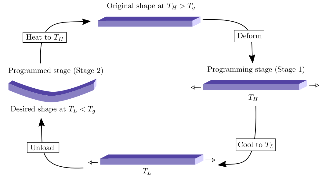
The shape shifting mechanism considered in [50, 68] involves two levels of temperature and one set of external loads, with one temperature higher than a critical transition temperature of the active materials (e.g., the glass transition temperature for shape memory polymers), and the other temperature lower than the critical temperature. The printed composite is first heated to , and the shape memory cycle starts at and proceeds as follows: First, external loads are applied to deform the printed composite while the temperature remains at , with the new configuration being known as the programming stage (or Stage 1). Then, the temperature is decreased while the loads are maintained on the printed composite, which are then removed once the temperature reached . The resulting shape at is the desired shape and we denote it as the programmed stage (or Stage 2). Increasing the temperature to enables the printed composite to recover its original shape, and this ends the shape memory cycle, see Figure 1 for the thermo-mechanical processing steps involving the two stages.
To capture the above behaviour, following [50] we consider a model for each stage. In the programming stage (Stage 1), we consider an elastic displacement and decompose the domain boundary into a partition with relative open subsets and such that and , where denotes the closure of a set , and we assign a prescribed displacement on and surface loads on . Under a linearised elasticity setting, the balance of momentum yields the following system of equations for the displacement :
| (2.1a) | |||||
| (2.1b) | |||||
| (2.1c) | |||||
with a phase-dependent elasticity tensor , body force , outer unit normal , and symmetrised gradient . One example of is
with constant tensors , .
After the change in temperature from to and after the programming loads in Stage 1 have been removed, the PAC experiences deformations due to residual stresses generated during the thermomechanical processing steps. When the temperature falls below , the active elastic materials undergo a phase transition from a soft rubbery state to a glassy state that has a higher Young’s modulus. We introduce a new variable to denote the displacement in the programmed stage (Stage 2), and as in [50], model the strains from the programming stage (Stage 1) as eigenstrains for . These eigenstrains are present only in the regions of active elastic materials, which we model with a fixity function . The shape fixity for a shape memory material is the ratio (expressed as a percentage) between the strain in the stress-free state after the programming step and the maximum strain [1]. For example, if the deformation elongates the material, the fixity quantifies the ability of the material to hold the temporary elongated length when the stress is removed. It is clear from the definition that for a passive elastic material, the fixity is zero, and so we set that in the region of the passive elastic material. Decomposing the domain boundary into a possibly different partition with relative open subsets and such that and , where we assign a prescribed displacement on and surface loads on , the equations for the programmed stage (Stage 2) read as
| (2.2a) | |||||
| (2.2b) | |||||
| (2.2c) | |||||
with a phase-dependent elasticity tensor and body force . In the above, the change in the elasticity tensor from in Stage 1 to in Stage 2 encodes the change in the elastic properties of the PAC when the temperature changes from to . Similarly to [50], here we have neglected the strains arising from thermal expansion in (2.1) and (2.2).
In the next section, under a suitable functional framework, we demonstrate that (2.1) and (2.2) are uniquely solvable, with the solution depending continuously on . Since controls the distribution of the passive and active elastic materials, it is natural to ask for specific material distributions that optimise certain cost functionals related to the design of PACs. Motivated from [50], we primarily focus on the following cost functional
| (2.3) |
where is a weighting factor, is a solution to (2.2) depending on (and also on , a solution to (2.1)), is a fixed weighting matrix, is a subset of the boundary , is a fixed constant related to the thickness of the interfacial regions , , indicates the standard -dimensional Hausdorff measure, and is a non-negative multi-well potential that attains its minimum at the corners (the unit vectors in ) of the Gibbs simplex . The first term in (2.3) consists of a target shape matching term, where we like to match the displacement in Stage 2 with a prescribed deformation over the surface by minimising the squared difference weighted by a matrix . The second term is the well-known Ginzburg–Landau functional in the multiphase setting that serves as a form of perimeter regularisation. It provides some form of regularity to our design solutions and penalises designs that have large interfaces between the different phases of elastic materials.
For our problem we introduce the design space
and our design problem can be formulated as the following
Remark 2.1.
For the existence theory for optimal designs to , it is also possible to consider a more general form of the cost functional:
with Carathéodory functions , and satisfying (see [14, Remark 5])
for any if and if , with functions , , , , and . In our current setting we have and .
Remark 2.2.
It is also possible to consider mass constraints for of the form
for fixed vectors (possibly also ), where in the above the inequalities are taken component-wise. These are convex constraints and thus when included into the definition of , the design space remains a closed and convex set. Then, in the corresponding necessary optimality condition, associated Lagrange multipliers will appear, see [13, 14] for more details.
Notation.
For a Banach space , we denote its topological dual by , and the corresponding duality pairing by . For any and , the standard Lebesgue and Sobolev spaces over are denoted by and with the corresponding norms and . In the special case , these become Hilbert spaces and we employ the notation with the corresponding norm . For our subsequent analysis, we introduce the spaces
and
For brevity, the corresponding norms are denoted by the same symbol if no confusion may arise. Vectors, matrices, and vector- or matrix-valued functions will be denoted by bold symbols. Furthermore, for a subset , we consider the function space
where denotes the trivial extension of to , and we endow it with the norm
We highlight that the above definition is not redundant as in general the trivial extension of a function does not belong to . Besides, we remark that is a Hilbert space and
forms a Hilbert triple (see, e.g., [48]).
For the forthcoming analysis we make the following structural assumptions.
-
(A1)
The domain , , is a bounded domain with or convex boundary that admits a partition with relative open subsets and such that and . Here, denotes the closure of the set . The same assumptions are made for and .
-
(A2)
The elasticity tensor is assumed to be a tensor-valued function
with , . Moreover, it fulfils the symmetry conditions
and there exist positive constants , and such that, for all ,
(2.4) (2.5) where , , and for every ,
The set consists of the symmetric -matrices. The same assumptions are made for .
-
(A3)
The multiwell potential possesses the form
where and the indicator function of the simplex is defined as
-
(A4)
The function is and there exist a positive constant such that
-
(A5)
The data of the problems satisfy
-
(A6)
The target displacement , where .
It is worth pointing out that condition (A3) entails that for every .
3 Analysis of the design optimisation problem
3.1 Linear elasticity system with mixed boundary conditions
In this section we provide a preliminary well-posedness result for the following linear elasticity system with mixed boundary conditions
| (3.1a) | |||||
| (3.1b) | |||||
| (3.1c) | |||||
The well-posedness of the system (3.1) is formulated as follows.
Proposition 3.1.
In addition to (A1), suppose that fulfils the symmetry conditions
| for all , |
and satisfies
| (3.2) |
for some positive constants and . Then, for every , and , there exists a unique weak solution to the elasticity system (3.1) in the sense that
| (3.3) |
and there exists a positive constant independent of such that
| (3.4) |
Note that whenever , we can identify the duality product in (3.3) as the standard boundary integral, that is,
Proof of Proposition 3.1.
The variational equality (3.3) admits a unique solution by a direct application of the Lax–Milgram theorem (cf., e.g., [5]). In this direction, we set
It is worth noticing that it readily follows from the assumptions on , , and that . With the above notation, (3.3) can then be rewritten as the variational problem
Thus, to apply the Lax–Milgram theorem, it is sufficient to show the bilinear form is continuous and coercive in . By (3.2) we have
while (3.2) and Korn’s inequality yield the -coercivity:
with a constant arising from Korn’s inequality. Thus, the existence and uniqueness of solving (3.3), as well as the estimate (3.4), readily follow from the Lax–Milgram theorem. ∎
We end this section with another abstract result that will be useful for the subsequent analysis. Consider the following problem with inhomogeneous data on the Dirichlet boundary:
| (3.5) | ||||||
Well-known theory yields that, for every , there exists a unique weak solution . The proof follows similarly to the above as a direct consequence of the Lax–Milgram theorem. This allows us to introduce the associated solution operator, that we call the extension operator
| (3.6) |
where is the unique weak solution to system (3.5).
3.2 Well-posedness of the state systems
Similarly to (3.5) and (3.6), we can introduce the extension operators and related to , and , , respectively. Then defining the functions allows us to transform (2.1) and (2.2) into the equivalent problems
| (3.7) | ||||||
and
| (3.8) | ||||||
where we set
For a cleaner presentation, we abuse notation and use the same variables and to denote and . Then, the well-posedness of (2.1) and (2.2) (equivalently (3.7) and (3.8)) are formulated as follows.
Theorem 3.1.
Proof.
Theorem 3.2.
Proof.
To start, let us set
Then, we consider the difference between the variational equalities (3.9)–(3.10) written for and for to infer that
| (3.13) | ||||
| (3.14) |
for all and Choosing and invoking condition (2.4) yields
| (3.15) | ||||
By Korn’s inequality we infer
| (3.16) |
Then, inserting in (3.14), and invoking the Lipschitz continuity of and from (A2) and (A4), as well as (3.16), yields
| (3.17) | ||||
Applying Korn’s inequality leads to (3.12). ∎
Corollary 3.1.
Suppose that (A1)–(A5) hold. Let and let be a sequence of functions in such that for all and strongly in as . Let denote the solutions to (3.9) and (3.10) corresponding to data , , , , , and . Then, it holds that, as ,
where are the unique solutions to (3.9) and (3.10) corresponding to data , , , , , and .
Proof.
From (3.11) we infer that and are bounded in and , respectively, and thus there exist limit functions such that, along a non-relabelled subsequence, in and in . To obtain strong convergence, in (3.13) and (3.14) we substitute , , , , and . Then, by virtue of the dominated convergence theorem, we infer the strong convergence, as ,
Hence, in the analogue of the first inequality in (3.15) we see that the integral on the right-hand side converges to zero, which implies via Korn’s inequality that
By the generalised dominated convergence theorem, we have the strong convergences
and thus, in the analogue of the first inequality in (3.17) we see that the integral on the right-hand side converges to zero, leading to the assertion
Thus, by combining the weak convergences with the above norms convergence the claim follows. ∎
The above analysis for systems (3.7) and (3.8) allows us to define some solution operators. Namely, we introduce
| (3.18) |
as well as the intermediate operators:
where and are the unique solutions obtained from Theorem 3.1. Then, the overall solution operator in (3.18) is simply the composition of the intermediate mappings and , i.e., . In particular, we can define the reduced cost functional
3.3 Existence of optimal designs
Proof.
As the proof is nowadays standard with the direct method of the calculus of variations, let us briefly outline the main points. Consider a minimising sequence for the reduced cost functional , which satisfies
This yields that is bounded in . By standard compactness arguments, since is closed and convex, we obtain a limit function such that weakly* in along a non-relabelled subsequence. Consequently, by (3.11) the sequence is bounded in , and on invoking Corollary 3.1 there exists a limit function such that, along a non-relabelled subsequence, strongly in as . Continuity of the boundary trace operator gives strongly in , and thus
By Fatou’s lemma and the a.e. convergence of to , we have
and using also the weak lower semicontinuity of the -norm, we infer that
This shows that is a solution to . ∎
4 Optimality conditions
To derive the first order necessary optimality conditions for , we first study the linearised system for the linearised variables introduced below, and use adjoint variables to provide a simplification of the optimality condition.
4.1 Linearised systems and Fréchet differentiability
Here, we analyse some differentiability properties of the solutions operators and introduced above. This will help us to formulate the first order optimality conditions of (P).
Theorem 4.1.
The solution operator is Fréchet differentiable at as a mapping from into . Moreover, it holds that
and its directional derivative at along a direction is given by
| (4.1) |
where is the unique weak solution to the following system:
| (4.2a) | |||||
| (4.2b) | |||||
| (4.2c) | |||||
in the sense
| (4.3) |
for all , where is the unique solution to (3.9) associated to obtained from Theorem 3.1.
Proof.
Firstly, the unique solvability of the linearised system (4.2) follows directly from the application of Proposition 3.1 upon choosing
Next, we take and such that , and set , i.e., . Since the first component of is just the identity in , we only need to investigate the Fréchet differentiability of the second component . In this direction, we denote
with being the unique solution to the linearised system (4.2) associated to and . Our aim is to show the existence of a positive constant such that
| (4.4) |
which would then imply the Fréchet differentiability of the operator . To this end, we subtract from (3.9) for the sum of (3.9) for and (4.3) for to obtain
Choosing and using (2.4) we infer that
Lipschitz continuity of yields a positive constant such that
| (4.5) |
and keeping in mind the estimate obtained from Theorem 3.2:
| (4.6) |
we find that
Then, by Korn’s inequality we infer (4.4), and whence the claimed Frechét differentiability of . ∎
Before presenting the Fréchet differentiability of , let us provide a formal discussion. Recall that and thus the directional derivative of at along a direction will be given by
where and represent the partial derivatives with respect to and , respectively. Hence, we expect to be a sum of two functions and , and the Fréchet differentiability of can be established by demonstrating
| (4.7) |
The result is formulated as follows.
Theorem 4.2.
The solution operator is Fréchet differentiable at as a mapping from into . Furthermore,
and its directional derivative at along a direction is given by
where is the unique weak solution to the following system:
| (4.8a) | |||||
| (4.8b) | |||||
| (4.8c) | |||||
in the sense that
| (4.9) | ||||
for all , where is the unique solution to (3.9) associated to and is the unique solution to (3.10) associated to . Moreover, and are the unique solutions to the following equations
| (4.10) | |||
| (4.11) |
for all .
Proof.
Unique solvability of (4.9), (4.10) and (4.11) are obtained by application of Theorem 3.1, and thus we focus on demonstrating the crucial estimate (4.7). Let , such that and . Setting
then, setting , (4.7) is equivalent to
We observe that by subtracting from (3.10) for the sum of (3.10) for and (4.9) for , we obtain
| (4.12) | ||||
Before proceeding with some computations, let us point out the following identities:
| (4.13) | ||||
and
| (4.14) | ||||
Similar to (4.5), we have, for positive constants and , that
| (4.15) | ||||
and upon choosing in (4.12), we infer that
| (4.16) |
Then, employing the Young and Hölder inequalities, (4.6), as well as the stability estimates
deduced from (3.12), we find that
and thus we obtain by Korn’s inequality
which verifies the Fréchet differentiability of . Furthermore, it is clear that by the uniqueness of the solutions, the sum is equal to . To establish the identification of the partial derivatives and , we argue as follows: Consider , so that from (4.11) we obtain that and . Then, in (4.12) with , we now have for the estimate (4.16), where
where we made use of . A short calculation shows that
which entails that . The other identification is in fact more straightforward as is a linear operator. This completes the proof. ∎
4.2 Adjoint systems
We now move to the investigation of some adjoint systems which, as typically happens in constrained minimisation problems, will allow us to simplify the formulation of the optimality conditions of .
Theorem 4.3.
As the proof of existence and uniqueness is simply an application of Theorem 3.1, we omit the details.
Remark 4.1.
Notice that the adjoint variable to the Stage 1 deformation is dependent on the adjoint variable to the Stage 2 deformation . This backwards dependence has some parallels with the adjoint systems associated to time-dependent state equations, which have to be solved backwards in time.
4.3 First order optimality conditions
Theorem 4.4.
Proof.
As is a non-empty, closed and convex set, standard results in optimal control and convex analysis yield that the first order necessary optimality condition for is
which reads, in view of Theorem 4.1 and Theorem 4.2, as
| (4.22) | ||||
where is the unique solution to (4.9) with , , , and from (4.3) (also with ). To simplify the above relation, the procedure is to compare the equalities obtained from (4.3) with , (4.9) with and , (4.18) with and (4.20) with . A short calculation then shows
which allows us to remove the dependence of from (4.22) and leads to (4.21). ∎
5 Sharp interface asymptotics
In this section we study the behaviour of solutions in the sharp interface limit . For , we denote
where is the solution operator defined in (3.18), so that the corresponding reduced functional can be expressed as the sum . The asymptotic behaviour of solutions can be studied under the framework of -convergence. In order to state the result some preparation is needed. A function is termed a function of bounded variation in , written as if there exists a matrix-valued measure of dimension on such that
for all where . Let where . For we set, for ,
and define the essential boundary as
where, for any , is the -ball in centered in , i.e., . Consider the extended functionals
with constants defined as
Then, the -convergence of to as is expressed as the following assertions:
-
•
Liminf property. If is a sequence such that and in , then with .
-
•
Limsup property. For any , there exists a sequence , such that in and .
-
•
Compactness property. Let be a sequence such that . Then, there exists a non-relabelled subsequence and a function such that in .
For a proof we refer to [8, Thm. 2.5 and Prop. 4.1], see also [11, Thm. 3.1 and Rmk. 3.3] with the choice .
5.1 Convergences of minimisers
Lemma 5.1.
For each , let denote a minimiser to the extended reduced cost functional . Then, there exists a non-relabelled subsequence and a limit function such that strongly in , , where
and is a minimiser to .
Proof.
The proof relies on the -convergence of the Ginzburg–Landau functional and the stability of -convergence under continuous perturbations. By Corollary 3.1, and the continuity of the trace operator, we see that is continuous. For arbitrary , we invoke the limsup property to find a sequence such that strongly in and . Continuity of implies as , leading to
As minimises , we see that
By the non-negativity of , the above estimate implies , and by the compactness property we deduce that there exists a limit function such that strongly in along a non-relabelled subsequence. Continuity of then gives and invoking the liminf property we subsequently infer that
As is arbitrary, this shows that is a minimiser of . We now return to the beginning of the proof and consider using the limsup property to construct a sequence that converges strongly to in . Then, following a similar argument we arrive at
which provides the claimed assertion . ∎
5.2 Formally matched asymptotic expansions
We turn our attention towards the optimality condition (4.21) and study its sharp interface limit with the method of formally matched asymptotic expansions, where we assume the functions , , , , and admit asymptotic expansions in powers of . From Lemma 5.1 we saw that converges to a function as , and thus for , we expect to change its values rapidly on a length scale proportional to . This inspires us to consider two asymptotic expansions of in the bulk and interfacial regions (to be defined below), and the procedure is to match these expansions in an intermediate region to deduce the expected equations in the sharp interface limit. We follow the ideas in [13] that treats a similar system of equations, and refer the reader to, e.g., [18, 25, 32, 33] for more details regarding the methodology.
Recalling as the set of corners of the Gibbs simplex , we partition the domain into regions , , where . Then, we assume the functions , , , , and are sufficiently smooth and admit the following asymptotic expansion in :
for all points away from the interfaces for , . This is known as the outer expansion. Furthermore, we assume that
where is the tangent space of the affine hyperplane , so that by the above construction for sufficiently small. We assume that there are constant elasticity tensors and for , satisfying the standard symmetric conditions and are positive definite. Then, for such that , we consider
Then, substituting the outer expansions into the state systems (2.1), (2.2) and the adjoint systems (4.17) and (4.19), to leading order we obtain the following equations for :
| (5.1) | ||||
where , and
| (5.2) | ||||
It then remains to furnish the above with boundary conditions for on the interfaces for , , which we assume are smooth hypersurfaces that can be obtained in the limit . These boundary conditions can be inferred with the help of a corresponding inner expansion for in the interfacial regions bordering two bulk regions and . To this end, we focus on one particular interface and introduce a change of coordinates with the help of a local parameterisation of , where is a spatial parameter domain.
Close to , consider the signed distance function such that if and if , so that the unit normal to points from to . Introducing the rescaled signed distance , a local parameterization of close to can be given as
This representation allows us to infer the following expansions for gradients, divergences and Laplacians [34]:
for scalar functions and vector functions , along with the curvature of , the surface gradient operator , and the surface divergence operator on . Then, for points close by , we assume an inner expansion of the form
Lastly, we assume in a tubular neighborhood of the outer expansions and the inner expansions hold simultaneously. Within this intermediate region certain matching conditions relating the outer expansions to the inner expansions must hold. For a scalar function admitting an outer expansion and an inner expansion , it holds that (see [34, Appendix D])
for . Consequently, we denote the jump of a quantity across as
Note that the above matching conditions also apply to vectorial functions. We introduce the orthogonal projection
where , so that the optimality condition (4.21) can be expressed in the following strong form
| (5.3) | ||||
We substitute the inner expansions into the equations (2.1a), (2.2a), (4.17a), (4.19a), and (5.3) and collect terms of the same order. Then, we perform some computations to deduce the boundary conditions posed on . As the subsequent analysis is similar to that performed in [13, 32], we omit most of the straightforward details. In the sequel we use the notation
for second order tensors and for .
To leading order , equations (2.1a) and (4.17a) yield
Multiplying by and , respectively, integrating over , integrating by parts and applying the matching conditions allow us to deduce that , and hence both and are constant in . Applying matching conditions we infer that
Then, to leading order , equations (2.2a) and (4.19a) yield
on account of the fact that . Hence, we also obtain
To first order , we get from (2.1a) and (4.17a) that
| (5.4) |
Integrating over and using the matching conditions yields
Similarly, from equations (2.2a) and (4.19a), we obtain to first order that
| (5.5) |
Integrating over and applying the matching conditions, we obtain
Turning now to the optimality condition (5.3), we use the fact that to see that the elasticity terms do not contribute to leading order and first order . Hence, to first order we obtain from (5.3) that
Following [18], can be chosen independent of and as the solution to the above ordinary differential system such that and . To the next order , we obtain
| (5.6) | ||||
where denotes the Hessian matrix of , and we have used that . Note that by the fact that for , and by the symmetry of the elasticity tensors , we have the relations
| (5.7) |
for any . To obtain a solution , a solvability condition has to hold, which can be derived by multiplying (5.6) with and integrating over . Using the relations , , after integrating by parts and applying the matching conditions, we obtain
| (5.8) | ||||
We employ the identities obtained from (5.4), (5.5) and (5.7) to obtain that
as well as to see that
Via a similar calculation we infer
and thus, setting , and applying matching conditions for and with , we obtain from (5.8) the solvability condition
| (5.9) | ||||
that has to hold on . Thus, the sharp interface limit consists of the equations (5.1) and (5.2) posed in , , furnished by the boundary conditions (5.9) and
on , .
5.3 Rigorous convergence in the two-phase setting
In the two phase case , since , we may use the difference to encode the vector , so that . Hence, the problem (P) can be re-phrased in terms of the scalar function ranging between and , and it suffices to consider the following
where , and, as no confusion can arise, we use the short-hand notations and for the functions and evaluated at . On recalling (A3), we hence assume that
| (5.10) |
for a . To simplify the calculations, we consider (homogeneous Dirichlet data), , and . We now consider deriving an alternative set of optimal conditions for a minimiser based on geometric variations. To this end, we consider the following admissible transformations and their corresponding velocity fields.
Definition 5.1.
The space of admissible velocity fields is defined as the set of all , where is a fixed small constant, such that it holds:
-
•
, and such that for all ;
-
•
for all ;
-
•
for all .
Then, the space of admissible transformations is defined as the set of solutions to the ordinary differential equations
with .
Notice that by the second property it holds for all . Let be an admissible velocity field with corresponding transformation . For we define , along with the unique solutions , where and .
Setting , by following a similar proof to [14, Lem. 25], we define for sufficiently small the function by
Using a change of variables , the relation
and also [57, Prop. 2.47] for the boundary transformation, we obtain
where for and denotes the -dimensional Hausdorff measure related to . From the properties of the mapping , we find that and . Hence, from the above identity we observe that
for all . Denoting by as the partial derivative of with respect to its second argument, we find that is given by
for all , where we have used the relation the identity matrix. As is an isomorphism by the Lax–Milgram theorem, the application of the implicit function theorem allows us to infer that the mapping
is differentiable at with derivative being the unique solution to the distributional equation
which reads as
| (5.11) | ||||
for all . In the above, we have made use of the following relations (see [57, Lem. 2.31, Prop. 2.36, Lem. 2.49])
Furthermore, substituting into (5.11), by means of Korn’s inequality and the smoothness of , we obtain the estimate
| (5.12) |
Via a similar procedure, for a small , we consider defined as
Then, by a change of variables , we find that
where . Since given by
is an isomorphism, by the implicit function theorem we infer that the mapping
is differentiable at with derivative being the unique solution to the distributional equation
which reads as
| (5.13) | ||||
for all . Substituting into (5.13), then using (5.12) and Korn’s inequality, we obtain the estimate
| (5.14) | ||||
The next result details an optimality condition for minimisers to obtained via geometric variations.
Theorem 5.1.
Remark 5.2.
Proof.
For any , let be the associated transformation and consider the scalar function for , where is sufficiently small. As is a minimiser of , we have
The directional derivative
can be obtained as in [41, Lem. 7.5]. Denoting by , then the derivative of can be obtained by a standard change of variables:
leading to (5.15). ∎
The convergence of (5.15) to the sharp interface limit is formulated as follows.
Theorem 5.2.
Suppose the hypotheses of Theorem 5.1 hold, and let be a minimiser to . For any with corresponding transformation , there exists a non-relabelled subsequence such that
where is a minimiser to the reduced functional , where the total variation for is defined as
Furthermore, and satisfy (5.11) and (5.13), respectively, with replaced by . Lastly, it holds that
| (5.16) |
where
| (5.17) | ||||
with as the generalised unit normal on the set .
Remark 5.3.
Proof.
The first two assertions on the convergence of and come from Lemma 5.1. Consequently, by the calculations in the proof of [27, Thm. 4.2] we infer the convergence, as ,
Next, from (5.11) and (5.13), we see that and satisfy
where and denotes the right-hand sides of (5.11) and (5.13), respectively. Thanks to Corollary 3.1, along a non-relabelled subsequence, and strongly as . Hence, together with the dominated convergence theorem, it is clear that, as ,
On the other hand, we infer from (5.12) and (5.14) that and are uniformly bounded in and , which then implies the existence of limit functions and , where
Lastly, using the compactness of the boundary-trace operator, we obtain, as ,
This shows (5.16) and completes the proof. ∎
6 Numerical simulations
In this section we present the finite element discretisation and showcase several numerical simulations in two and three dimensions for the two-phase case. Namely, we have and we consider the optimal distribution of a single type of active material within a passive material.
6.1 Finite element discretisation
We assume that is a polyhedral domain and let be a regular triangulation of into disjoint open simplices. Associated with are the piecewise linear finite element spaces
where we denote by the set of all affine linear functions on , cf. [22]. In addition we define
| (6.1) |
as well as
We also let denote the –inner product on , and let be the usual mass lumped –inner product on associated with . In addition, for any fourth order tensor and any matrices and . Finally, denotes a chosen uniform time step size.
We now introduce finite element approximations of the state equations (3.9) and (3.10), adjoint systems (4.18) and (4.20), as well as the optimality conditions (4.21) with a pseudo-time evolution based on an -gradient flow approach. In particular, we consider the obstacle potential (5.10) with , which leads to a variational inequality.
The fully discrete numerical scheme is formulated as follows: Given , find such that
| (6.2a) | |||
| (6.2b) | |||
| (6.2c) | |||
| (6.2d) | |||
| (6.2e) | |||
We implemented the scheme (6.2) with the help of the finite element toolbox ALBERTA, see [56]. To increase computational efficiency, we employ adaptive meshes, which have a finer mesh size within the diffuse interfacial regions and a coarser mesh size away from them, see [9, 10] for a more detailed description.
Clearly, we first solve the linear systems (6.2a) in order to obtain , then (6.2b) for , then (6.2c) for , then (6.2d) for , and finally the variational inequality (6.2e) for . In two space dimensions we employ the package LDL, see [23], together with the sparse matrix ordering AMD, see [6], in order to solve the linear systems (6.2a)–(6.2d). In three space dimensions, on the other hand, we use a preconditioned conjugate gradient algorithm, with a -cycle multigrid step as preconditioner. In order to solve the variational inequality (6.2e) we employ a nonlinear multigrid method similar to [42].
For the computational domain we will choose in two dimensions, and in three dimensions with positive lengths , , given below. For the physical parameters we loosely follow the settings in [50]. In particular, for the forcings we choose throughout, as well as and
| (6.3) |
For the interpolated elasticity tensors we choose , where the two tensors are defined through the Young’s moduli and Poisson ratios via
| (6.4) |
Similarly, , with the Young’s moduli and Poisson ratios
| (6.5) |
For the fixity function we choose
| (6.6) |
For the visualisation of the progress of the discrete gradient flow computations, we define the discrete cost functional
| (6.7) |
As the initial data we choose a random mixture with mean zero. Choosing other initial data, including random mixtures with positive or negative mean had no visible influence on the obtained optimal shapes.
6.2 Numerical simulations in two dimensions
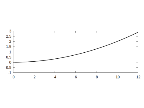
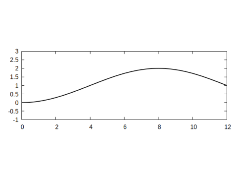
For the target shapes we consider the parabolic profile
| (6.8a) | |||
| with , and the cosine profile | |||
| (6.8b) | |||
with and . In Figure 2 we plot two examples for the profiles in (6.8) for the domain length .
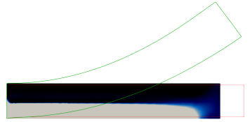
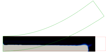
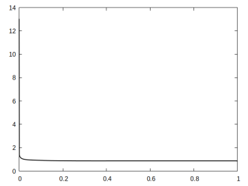
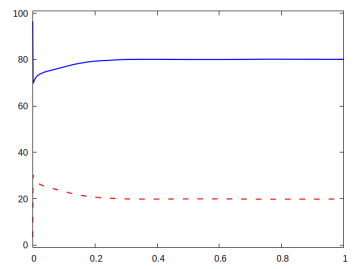
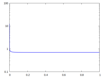
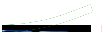
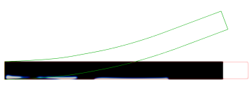
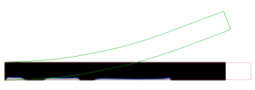
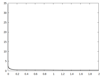
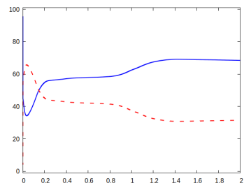
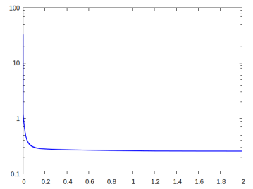
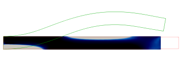
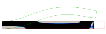
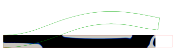
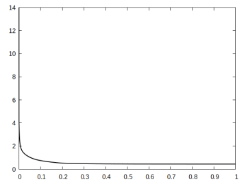
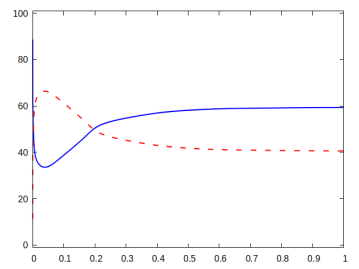
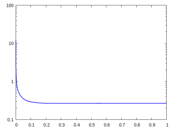
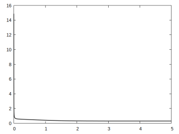
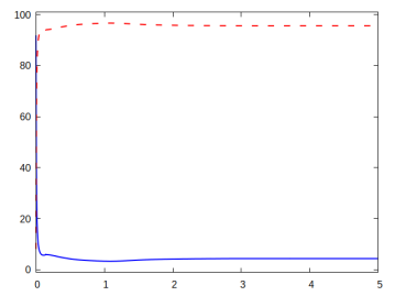
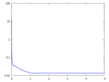
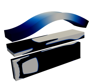
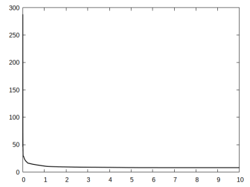
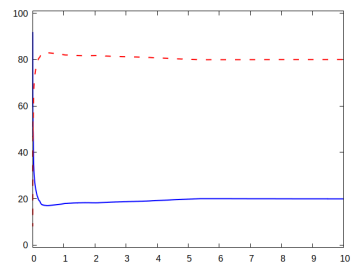
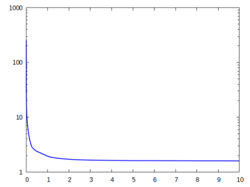
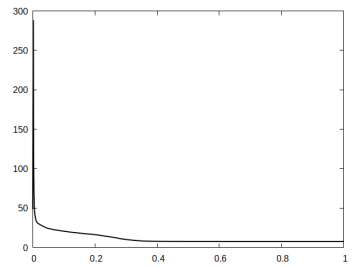
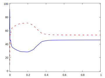
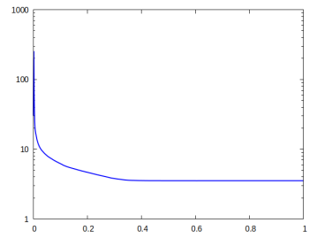
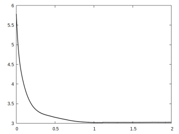
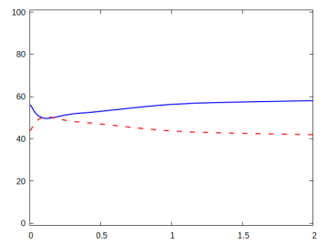
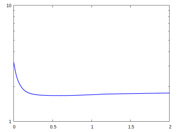
In each of the Figures 3, 4, 5 and 6, we provide visualisations of the numerical solution at various pseudo-times (black denotes the passive material and grey denotes the active material ), and the corresponding displacements (in red) and (in green). As mentioned before, each time the gradient flow is started from a random mixture with zero mean. We also provide pseudo-time plots of the cost functional , the proportion of the elastic and interfacial energies, as well as log-plots of the elastic energies. The parameter details are summarised in the Table 1.
| Figure | Profile | Domain | ||||
|---|---|---|---|---|---|---|
| 3 | Parabolic (6.8a) | - | ||||
| 4 | Cosine (6.8b) | |||||
| 5 | Parabolic (6.8a) | - | ||||
| 6 | Cosine (6.8b) |
For all the presented simulations we choose the parameters and . In each case the cost functional decreases monotonically, but the proportions of the two energies (elastic vs interfacial) differ from case to case.
The first experiment in Figure 3 is for the parabolic profile on the domain . We observe that in the optimal distribution of material, the active phase occupies most of the lower domain. This ensures that in the programmed stage, the printed active composite is able to attain the desired target shape.
Not surprisingly, a very different distribution of material is obtained when changing the target shape functional to enforce a cosine profile at the programmed stage. As can be seen from Figure 3, the optimal distribution of the active material is now given by an elongated region that connects the lower left of the domain with the upper right.
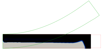
It turns out that on longer (or thinner) domains, far less active material is needed to achieve significant deformations at the programmed state. For example, in Figure 4 a miniscule amount of active material, spread in several connected components arranged at the bottom of the domain, is sufficient to result in the desired parabolic target shape.


Similarly, we observe in Figure 5 that three strategically placed small amounts of active material guarantee a cosine profile at the programmed stage for the printed active composite.
6.3 Numerical simulations in three dimensions
For the target shapes we consider a function of the form
and choose from one of the following:
| (6.9) |
| (6.10) |
| (6.11) |
Notice that (6.9) and (6.10) are simply the three dimensional analogues of the parabolic profile (6.8a) and the cosine profile (6.8b), respectively. On the other hand, (6.11) yields a linear profile in with a twisting in the -direction.
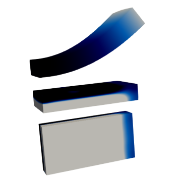
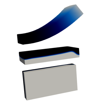
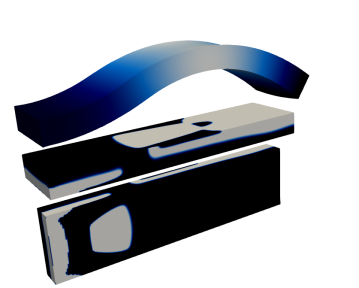
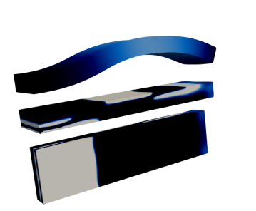
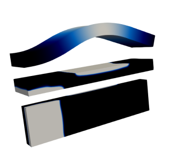
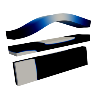
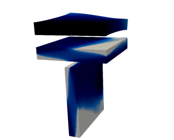
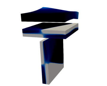
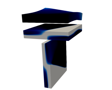
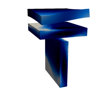
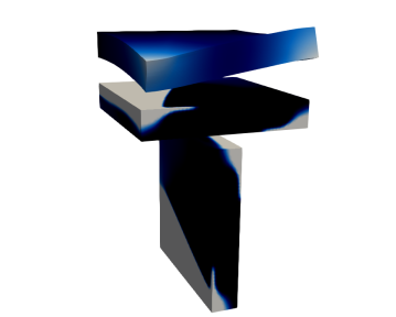
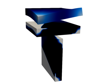
In each of the Figures 7, 8, and 9, 10 we provide visualisations of the numerical solution at various pseudo-times (black denotes the passive material and grey denotes the active material ), and the corresponding displacements (darker colours indicating lower values of and lighter colours indicating higher values of ). We also provide pseudo-time plots of the energy functionals, similarly to the 2D simulations in the previous subsection. The parameter details are summarised in the Table 2.
| Figure | Profile | Domain | ||||
|---|---|---|---|---|---|---|
| 7 | (6.9) | - | ||||
| 8 | (6.10) | 1 | 2 | |||
| 9 | (6.10) | |||||
| 10 | (6.11) | - |
In the first three figures we take and for choose either or . In each simulation the cost functional decreases monotonically, but the proportions of the two energies (elastic vs interfacial) differ from case to case.
The first simulation is a direct 3D analogue for the computation previously shown in Figure 3, the only difference being that here we restrict the set to the upper part of the boundary . As expected, the observed results are very close to the ones seen previously in the 2D setting. In particular, the active phase occupies the lower half of the domain, with a dip towards the right end of the domain.
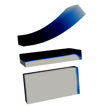
On more elongated domains we once again observe that relatively little active material can result in large deformations at the programmed stage. For example, the strategic placement of the active component seen in Figure 8 yields a large cosine profile deformation.
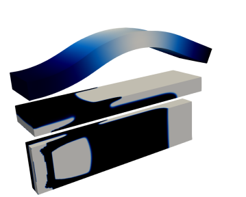
It is interesting to note that by simply changing the weighting matrix in the target energy functional, we obtain a completely different optimal distribution of active material. This can be seen in Figure 9, where the only change to the previous simulation is , rather than . Now there are just two connected components for the active phase, one at the lower left part of the domain, and one at the middle of the top of the domain. Yet the obtained deformations at the programmed stage are very similar.
Our final numerical simulation is for a twisted target shape. In particular, we use the target function (6.11) with on the domain , with and . In Figure 10 we provide visualisations of the numerical solution at various pseudo-times, and the corresponding displacements (here darker colours indicate lower values of and lighter colours indicate higher values of ). For this computation we take and . At the optimal configuration we observe an elaborate distribution of the active material, which yields a twisted shape of the component at the programmed stage.
Acknowledgments
The authors HG and AS gratefully acknowledge the support by the Graduiertenkolleg 2339 IntComSin of the Deutsche Forschungsgemeinschaft (DFG, German Research Foundation) – Project-ID 321821685. The work of KFL is supported by the Research Grants Council of the Hong Kong Special Administrative Region, China [Project No.: HKBU 14302218 and HKBU 12300321].
References
- [1] S.A. Abdullah, A. Jumahat, N.R. Abdullah and L. Frormann. Setermination of Shape Fixity and Shape Recovery Rate of Carbon Nanotube-flled Shape Memory Polymer Nanocomposites. Procedia Eng. 41 (2012) 1641–1646
- [2] M.H. Ali, A. Abilgaziyev and D. Adair. 4D printing: a critical review of current developments, and future prospects. Int. J. Adv. Manuf. Technol. 104 (2019) 701–717
- [3] G. Allaire and B. Bogosel. Optimizing supports for additive manufacturing. Struct. Multidiscip. Optim. 58 (2018) 2493–2515
- [4] S. Almi and U. Stefanelli. Topology optimization for incremental elastoplasticity: A phase-field approach. SIAM J. Control Optim. 59 (2021) 339–364
- [5] H.W. Alt: Linear Functional Analysis, an Application Oriented Introduction. Springer, London, (2016)
- [6] P.R. Amestoy, T.A. Davis and I.S. Duff. Algorithm 837: AMD, an approximate minimum degree ordering algorithm. ACM Trans. Math. Software 30 (2004) 381–388
- [7] S.E. Bakarich, E. Gorkin and G.M. Spinks. 4D printing with mechanically robust, thermally actuating hydrogels. Macromol. Rapid Commun. 36 (2015) 1211–1217
- [8] S. Baldo. Minimal interface criterion for phase transitions in mixtures of Cahn–Hilliard fluids. Ann. Inst. H. Poincaré Anal. Non Linéaire 7 (1990) 67–90
- [9] L. Baňas and R. Nürnberg. Finite element approximation of a three dimensional phase field model for void electromigration. J. Sci. Comp. 37 (2008) 202–232
- [10] J.W. Barrett, R. Nürnberg and V. Styles. Finite element approximation of a phase field model for void electromigration. SIAM J. Numer. Anal. 42 (2004) 738–772
- [11] G. Bellettini, A. Braides and G. Riey. Variational approximation of anisotropic functionals on partitions. Annali di Matematica 184 (2005) 75–93
- [12] A. Bhattacharyya and K.A. James. Topology optimization of shape memory polymers structures with programmable morphology. Struct. Multidiscip. Optim. 63 (2021) 1863–1887
- [13] L. Blank, H. Garcke, M. Hassan Farshbaf-Shaker and V. Styles. Relating phase field and sharp interface approaches to structural topology optimization. ESAIM: Control Optim. Calc. Var. 20 (2014) 1025–1058
- [14] L. Blank, H. Garcke, C. Hecht and C. Rupprecht. Sharp interface limit for a phase field model in structural optimization. SIAM J. Control Optim. 54 (2016) 1558–1584
- [15] L. Blank, H. Garcke, L. Sarbu, T. Srisupattarawanit, V. Styles and A. Voigt. Phase-field approaches to structural topology optimization, in Constrained optimization and optimal control for partial differential equations, vol. 160 of Internat. Ser. Numer. Math., Birkhäuser/Springer Basel AG, Basel, 2012, 245–256
- [16] J.F. Blowey and C.M. Elliott. Curvature dependent phase boundary motion and parabolic double obstacle problems, in Degenerate diffusions (Minneapolis, MN, 1991), vol. 47 of IMA Vol. Math. Appl., Springer, New York, 1993, 19–60
- [17] B. Bourdin and A. Chambolle. Design-dependent loads in topology optimization. ESAIM: Control Optim. Cal. Var. 9 (2003) 19–48
- [18] L. Bronsard, H. Garcke and B. Stoth. A multi-phase Mullins-Sekerka system: matched asymptotic expansions and an implicit time discretization for the geometric evolution problem. SIAM J. Appl. Math. 60 (1999) 295–315
- [19] M. Burger and R. Stainko. Phase-field relaxation of topology optimization with local stress constraints. SIAM J. Control Optim. 45 (2006) 1447–1466
- [20] S. Cacace, E. Cristiani and L. Rocchi. A Level Set Based Method for Fixing Overhangs in 3D Printing. Appl. Math. Model. 44 (2017) 446–455
- [21] M. Carraturo, E. Rocca, E. Bonetti, D. Hömberg, A. Reali and F. Auricchio. Graded-material design based phase-field and topology optimization. Comput. Mech. 64 (2019) 1589–1600
- [22] P.G. Ciarlet: The Finite Element Method for Elliptic Problems. North-Holland Publishing Co., Amsterdam, (1978)
- [23] T.A. Davis, Algorithm 849: a concise sparse Cholesky factorization package. ACM Trans. Math. Software 31 (2005) 587–591
- [24] Z. Ding, C. Yuan, X. Peng, T. Wang, JH.J. Qi and M.L. Dunn. Direct 4D printing via active composite materials. Sci. Adv. 3 (2017) e1602890
- [25] P.C. Fife and O. Penrose. Interfacial dynamics for thermodynamically consistent phase-field models with nonconserved order parameter. J. Differential Equations 16 (1995) 1–49
- [26] J. Jiang, X. Xu and J. Stringer. Support Structures for Additive Manufacturing: A Review. J. Mauf. Mater. Process. 2 (2008) 64 (23 pages)
- [27] H. Garcke. The -limit of the Ginzburg–Landau energy in an elastic medium. AMSA 18 (2008) 345–379
- [28] H. Garcke and C. Hecht. Apply a phase field approach for shape optimization of a stationary Navier-Stokes flow. ESAIM: Control Optim. Cal. Var. 22 (2016) 309–337
- [29] H. Garcke and C. Hecht. Shape and topology optimization in Stokes flow with a phase field approach. Appl. Math. Optim. 73 (2016) 23–70
- [30] H. Garcke, C. Hecht, M. Hinze, C. Kahle and K.F. Lam. Shape optimization for surface functionals in Navier–Stokes flow using a phase field approach. Interfaces Free Bound. 18 (2016) 219–261
- [31] H. Garcke, P. Hüttl and P. Knopf. Shape and topology optimization involving the eigenvalues of an elastic structure: A multi-phase-field approach. Adv. Nonlinear Anal. 11 (2022) 159–197
- [32] H. Garcke, K.F. Lam, R. Nürnberg and A. Signori. Overhang penalization in additive manufacturing via phase field structural topology optimization with anisotropic energies. Preprint ArXiv:2111.14070
- [33] H. Garcke, B. Nestler and B. Stoth. On anisotropic order parameter models for multi0phase systems and their sharp interface limits. Phys. D 115 (1998) 87–108
- [34] H. Garcke and B. Stinner. Second order phase field asymptotics for multi-component systems. Interfaces Free Bound. 8 (2006) 131–157
- [35] Q. Ge, C.K. Dunn, H.J. Qi and M.L. Dunn. Active origami by 4D printing. Smart Mater. Struct. 23 (2014) 094007
- [36] O. Kuksenok and A.C. Balazs. Stimuli-responsive behavior of composites integating thermo-responsive gels with photo-responsive fibers. Mater. Horizons 3 (2016) 53–62
- [37] Q. Ge, H.J. Qi and M.L. Dunn. Active materials by four-dimension printing. Appl. Phys. Lett. 103 (2013) 131901
- [38] Q. Ge, A.H. Sakhaei, H. Lee, C.K. Dunn, N.X. Fang and M.L. Dunn. Multimaterial 4D Printing with Tailorable Shape Memory Polymers. Sci. Rep. 6 (2016) 31110
- [39] M.J. Geiss, N. Boddeti, O. Weeger, K. Maute and M.L. Dunn. Combined level-set-XFEM-density topology optimization of four-dimensional printed structures undergoing large deformation. J. Mech. Des. 141 (2019) 051405
- [40] M. Howard, J. Pajot, K. Maute and M.L. Dunn. A Computational Design Methodology for Assembly and Actuation of Thin-Film Structures via Patterning of Eigenstrains. J. Microelectromech. Syst. 18 (2009) 1137–1148
- [41] C. Hecht. Shape and topology optimization in fluids using a phase field approach an application in structural optimization. PhD Thesis University of Regensburg, Regensburg, Germany 2014 https://epub.uni-regensburg.de/29869/1/Dissertation_ClaudiaHecht.pdf
- [42] R. Kornhuber. Monotone multigrid methods for elliptic variational inequalities II. Numer. Math. 72 (1996) 481–499
- [43] M. Leray, L. Merli, F. Torti, M. Mazur and M. Bandt. Optimal topology for additive manufacturing: A method for enabling additive manufacture of support-free optimal structures. Mater. Des. 63 (2014) 678–690
- [44] J. Liu, A.T. Gaynor, S. Chen, Z. Kang, K. Suresh, A. Takezawa, L. Li, J. Kato, J. Tang, C.C.L. Wang, L. Cheng, X. Liang and A.C. To. Current and future trends in topology optimization for additive manufacturing. Struct. Multi. Optim. 57 (2018) 2457–2483
- [45] J. Liu and H. Yu. Self-Supporting Topology Optimization With Horizontal Overhangs for Additive Manufacturing. J. Manuf. Sci. Eng. 142 (2020) 091003 (14 pages)
- [46] M. Langelaar. Combined optimization of part topology, support structure layout and build orientation for additive manufacturing. Struct. Multidiscip. Optim. 57 (2018) 1985–2004
- [47] H. Li, X. Gao and Y. Luo. Multi-shape memory polymers achieved by the spatio-assembly of 3D printable thermoplastic building blocks. Soft Matter 12 (2016) 3226–3233
- [48] J.L. Lions and E. Magenes. Non-homogeneous boundary value problems and applications. Springer, 1972.
- [49] T.S. Lumpe and K. Shea. Computational design of 3D-printed active lattice structures for reversible shape morphing. J. Mater. Res. 36 (2021) 3642–3655
- [50] K. Maute, A. Tkachuk, J. Wu, H.J. Qi, Z. Ding and M.L. Dunn. Level Set Topology Optimization of Printed Active Composites. J. Mech. Des. 137 (2015) 111402 (13 pages)
- [51] A.M. Mirzendehdel and K. Suresh. Support Structure Constrained Topology Optimization for Additive Manufacturing. Comput. Aided Des. 1 (2016) 1–13
- [52] F. Momeni, S.M. Hassani, N.X. Liu and J. Ni. A review of 4D printing. Mater. Des. 122 (2017) 42–79
- [53] N.C. Owen, J. Rubinstein, P. Sternberg. Minimizers and gradient flows for singularly perturbed bi-stable potentials with a Dirichlet condition. Proc. R. Soc. Lond. A 429 (1990) 505–532
- [54] J.M. Pajot, K. Maute, Y. Zhang and M.L. Dunn. Design of patterned multilayer films with eigenstrains by topology optimization. Int. J. Solids Struct. 43 (2006) 1832–1853
- [55] P. Penzler, M. Rumpf and B. Wirth. A phase-field model for compliance shape optimization in nonlinear elasticity. ESAIM Control Optim. Cal. Var. 18 (2012) 229–258
- [56] A. Schmidt and K.G. Siebert. Design of Adaptive Finite Element Software: The Finite Element Toolbox ALBERTA. vol. 42 of Lecture Notes in Computational Science and Engineering, Springer-Verlag, Berlin, 2005
- [57] J. Sokolowski and J.-P. Zolesio. Introduction to Shape Optimization. Springer series in computational mathematics, Vol. 16, Springer-Verlag, Berlin Heidelberg, 1991
- [58] L. Sun and W.M. Huang. Mechanisms of the multi-shape memory effect and temperature memory effect in shape memory polymers. Soft Matter 6 (2010) 4403–4406
- [59] Y. Sun, W. Ouyang, Z. Liu, N. Ni, Y. Savoye, P. Song and L. Liu. Computational Design of Self-actuated Deformable Solids via Shape Memory Material. IEEE Trans. Vis. Comput. Graph. —bf 28 (2022) 2577–2588
- [60] A. Takezawa, S. Nishiwaki and M. Kitamura. Shape and topology optimization based on the phase field method and sensitivity analysis. J. Comput. Phys. 229 (2010) 2697–2718
- [61] S. Tibbits. 4D printing: Multi-material shape change. Archit. Des. 84 (2014) 116–121
- [62] M.Y. Wang and S. Zhou. Phase field: a variational method for structural topology optimization. CMES Comput. Model. Eng. Sci. 6 (2004) 547–566
- [63] X. Wan, Y. He, Y. Liu and J. Leng. 4D printing of multiple shape memory polymer and nanocomposites with biocompatible programmable and selectively actuated properties. Addit. Manuf. 53 (2022) 102689
- [64] G. Wang, H. Yang, Z. Yan, N.G. Ulu, Y. Tao, J. Gu, L.B. Kara and L. Yao. 4DMesh: 4d printing morphing non-developable mesh surfaces. in the 31st Annual ACM Symposium on User Interface Software and Technology (2018) 623–635
- [65] Y. Wei, P. Huang, Z. Li, P. Wang and X. Feng. Design of active materials distributions for four-dimensional printing based on multi-material topology optimization. Smart Mater. Struct. 30 (2021) 095002
- [66] J. Wu, C. Yuan, Z. Ding, M. Isakov, Y. Mao, T. Wang, M.L. Dunn and H.J. Qi. Multi-shape active composites by 3D printing of digital shape memory polymers. Sci. Rep. 6 (2016) 24224
- [67] C. Yuan, T. Lu and T.J. Wang. Mechanics-based design strategies for 4D printing: A review. Forces Mech. 7 (2022) 100081.
- [68] Q. Zhang, K. Zhang and G. Hu. Smart three-dimensional lightweight structure triggered from a thin composite sheet via 3D printing technique. Sci. Rep. 6 (2016) 22431