Parallel multilevel restricted Schwarz preconditioners for implicit simulation of subsurface flows with Peng-Robinson equation of state
Abstract
Parallel algorithms and simulators with good scalabilities are particularly important for large-scale reservoir simulations on modern supercomputers with a large number of processors. In this paper, we introduce and study a family of highly scalable multilevel restricted additive Schwarz (RAS) methods for the fully implicit solution of subsurface flows with Peng-Robinson equation of state in two and three dimensions. With the use of a second-order fully implicit scheme, the proposed simulator is unconditionally stable with the relaxation of the time step size by the stability condition. The investigation then focuses on the development of several types of multilevel overlapping additive Schwarz methods for the preconditioning of the resultant linear system arising from the inexact Newton iteration, and some fast solver technologies are presented for the assurance of the multilevel approach efficiency and scalability. We numerically show that the proposed fully implicit framework is highly efficient for solving both standard benchmarks as well as realistic problems with several hundreds of millions of unknowns and scalable to 8192 processors on the Tianhe-2 supercomputer.
keywords:
Reservoir simulation , Fully implicit method , Multilevel method , Restricted Schwarz preconditioners , Parallel computing1 Introduction
Simulation of subsurface fluid flows in porous media is currently an important topic of interest in many applications, such as hydrology and groundwater flow, oil and gas reservoir simulation, CO2 sequestration, and waste management [8, 13]. The extensive growing demand on accurate modeling subsurface systems has produced persistent requirements on the understanding of many different physical processes, including multiphase fluid flow and transport, fluid phase behavior with sophisticated equation of state, and geomechanical deformations. To simulate these processes, one needs to solve a set of coupled, nonlinear, time-dependent partial differential equations (PDEs) with complicated nonlinear behaviors arising from the complexity of the geological media and reservoir properties. Additional computational challenge comes from the involving of Peng-Robinson equation of state, which governs the equilibrium distribution of fluid and has a remarkable influence on the high variation of the Darcy velocity. Due to their high computational complexity, numerically approximating subsurface phenomena with high resolution is critical to the reservoir engineering for accurate predictions of costly projects. Hence, parallel reservoir simulators equipped with robust and scalable solvers on high performance computing platforms are crucial to achieve efficient simulations of this intricate problem [9].
In terms of the numerical solution of partial differential equations, the fully implicit method [2, 3, 17, 20, 24, 26, 32, 36] is a widely preferred approach to solve various problems arising from the discretization of subsurface fluid flows. The fully implicit scheme is unconditionally stable and can relax the stability requirement of the Courant-Friedrichs-Lewy (CFL) condition. It therefore provides a consistent and robust way to simulate the subsurface fluid flow problem in long-term and extreme-scale computations. In particular, a great advantage of the fully implicit algorithm is that the corresponding nonlinear equations are implicitly solved in a monolithic way. This characteristic feature strengthens its potential to allow the addition of more physics and the introduction of more equations without changing much of the simulator framework, which greatly expands the scope of application of the fully implicit approach. In spite of being stable for arbitrary large time steps, when a fully implicit scheme is applied, one must solve a large, sparse, and ill-conditioned linear system at each nonlinear iteration. It remains challenging and important to design robust and scalable solvers for the large scale simulations on high performance computing platforms. In this study, we employ the framework of Newton–Krylov algorithms [5, 7, 11, 15, 21, 34] to guarantee the nonlinear consistency, and mainly focus our efforts on designing an efficient preconditioning strategy to substantially reduce the condition number of the linear system.
In reservoir simulations, some effective preconditioning techniques, such as block preconditioners [14, 18, 33], the Constrained Residual Pressure (CPR) preconditioning approach [30, 31, 32], the domain decomposition methods [20, 26, 36, 37], and the algebraic or geometric multigrid algorithms [2, 3, 24, 32], are flexible and capable of addressing the inherent ill-conditioning of a complicated physics system, and hence have received increasingly more attentions in recent years. The focus of this paper is on the domain decomposition approach by which we propose a family of one-level or multilevel restricted additive Schwarz preconditioners. The original overlapping additive Schwarz (AS) method was introduced for the solution of symmetric positive definite elliptic finite element problems, and was later extended to many other nonlinear or linear systems [6, 29]. In the AS method, it follows the divide-and-conquer technique by recursively breaking down a problem into more sub-problems of the same or related type, and its communication only occurs between neighboring subdomains during the restriction and extension processes. Moreover, the additive Schwarz preconditioner does not require any splitting of the nonlinear system. Hence, it can serve as a basis of efficient algorithms that are naturally suitable for massively parallel computing. In particular, the approach can be combined with certain variants of restriction operators in a robust and efficient way, such as the so-called restricted additive Schwarz (RAS) method proposed by Xiao-Chuan Cai et al. in [4, 6]. Hence, it can significantly improve the physical feasibility of the solver and substantial reduce the total computing time, and has proven to be very efficient in a variety of applications [16, 23, 26, 32, 36, 38]. Recently, the overlapping restricted additive Schwarz method in conjunction with a variant of inexact Newton methods has been applied successfully to the two-phase flow problem [36] and the black oil model [32, 37]. It was demonstrated that the one-level Schwarz preconditioner is scalable in terms of the numbers of nonlinear and linear iterations, but not in terms of the total compute time when the number of processors becomes large, which means the requirement of the family of multilevel methods [16, 23, 28, 29].
In this work, to take advantage of modern supercomputers for large-scale reservoir simulations, we propose and develop the overlapping restricted additive Schwarz preconditioner into a general multilevel framework for solving discrete systems coming from fully implicit discretizations. We show that, with this new feature, our proposed approach is more robust and efficient for problems with highly heterogeneous media, and can scale optimally to a number of processors on the Tianhe-2 supercomputer. We would like to pointing out that designing a good strategy for the multilevel approach is both time-consuming and challenging, as it requires extensive knowledge of the general-purpose framework of interests, such as the selection of coarse-to-fine mesh ratios, the restriction and interpolation operators, and the solvers for the smoothing and coarse-grid correction. To the best of our knowledge, very limited research has been conducted to apply the multilevel restricted additive Schwarz preconditioning technique for the fully implicit solution of petroleum reservoirs.
The outline of the paper is as follows. In Section 2, we introduce the governing equations of subsurface flows with Peng-Robinson equation of state, followed by the corresponding fully implicit discretization. In Section 3, a family of multilevel restricted additive Schwarz preconditioners, as the most important part of the fully implicit solver, is presented in detail. We show numerical results for some 2D and 3D realistic benchmark problems in Section 4 to demonstrate the robustness and scalability of the proposed preconditioner. The paper is concluded in Section 5.
2 Mathematical model and discretizations
The problem of interest in this study is the compressible Darcy flow in a porous medium for the description of gas reservoir simulations [8, 9, 13]. Let be the computational domain with the boundary , and denote the final simulated time. The mass balance equation with the Darcy law for the real gas fluid is defined by
| (1) |
where is the porosity of the porous medium, is the permeability tensor, is the Darcy’s velocity, denotes the density, is the viscosity of the flow, is the pressure, and is the external mass flow rate. The Peng-Robinson (PR) equation of state (EOS) [13] is used to describe the density as a function of the composition, temperature and pressure:
| (2) |
where is the molecular weight, is the temperature, is the gas constant, and is the compressibility factor of gas defined by
| (3) |
Moreover, and are the PR-EOS parameters defined as follows:
where the parameters and are modeled by imposing the criticality conditions
| (4) |
with () being the specific pressure (temperature) in the critical state of the gas, and being the reduced temperature defined as . In addition, the parameter in (4) is a fitting formula of the acentric factor of the substance:
| (5) |
Here, the acentric factor is calculated by the following formula:
where and are given by
with the normal boiling point temperature and the reduced normal boiling point temperature defined as .
In this study, we take the pressure as the primary variable. Suppose that the porosity is not changed with the time, then the equations of the mathematical model can be rewritten by substituting (2) and (3) into (1) as follows:
| (6) |
where the relations are given by
with the initial condition . Suppose the boundary of the computational domain is composed of two parts with . The boundary conditions associated to the model problem (6) are
where n is the outward normal of the boundary . We remark that the compressibility factor as an intermediate variable is obtained by solving the algebraic cubic equation (3) with the primary variable , see the references [8, 9] for the computation of in details.
We employ a cell-centered finite difference (CCFD) method for the spatial discretization, for which the details can be found in [8, 9, 22, 39], and then a fully implicit scheme is applied for the time integration [2, 16, 32, 36]. For a given time-stepping sequence , define the time step size and use superscript to denote the discretized evaluation at time level . After spatially discretizing (6) by the CCFD scheme, we have a semi-discrete system
| (7) |
where is the operator of the spatial discretization at time level by using the CCFD method. For the purpose of comparison, we implement both the first-order backward Euler scheme (BDF-1) and second-order backward differentiation formula (BDF-2) for the temporal integration of (7). For the BDF-1 scheme, the fully discretized system reads
| (8) |
where is the evaluation of at the time step with a time step size . And the fully discretized system for the BDF-2 method is
| (9) |
Note that, for the BDF-2 scheme, the BDF-1 method is used at the initial time step.
Remark 1
The employed CCFD discretization for (6) on rectangular meshes can be viewed as the mixed finite element method with Raviart-Thomas basis functions of lowest order equipped with the trapezoidal quadrature rule [8, 9, 22]. We also would like to pointing out that the proposed solver technologies introduced in the following section can be extended to solve the systems arising from the other spatial discretization schemes.
3 Multilevel restricted Schwarz preconditioners
When the fully implicit method is applied, a system of nonlinear algebraic equations after the temporal and spatial discretizations,
| (10) |
is constructed and solved at each time step. In (10), the vector is a given nonlinear vector-valued function arising from the residuals function in (8) or (9) given by with , and . In this study, the nonlinear system (10) is solved by a parallel Newton-Krylov method with the family of domain decomposition type preconditioners [5, 7, 11, 15].
Let the initial guess for Newton iterations at current time step be the solution of the previous time step, then the new solution is updated by the current solution and a Newton correction vector as follows:
| (11) |
where is the step length calculated by a cubic line search method [12] to satisfy
with the parameter being fixed to in practice. And the Newton correction is obtained by solving the following Jacobian linear system
| (12) |
with a Krylov subspace iteration method [25]. Here, is the Jacobian matrix obtained from the current solution . Since the corresponding linear system from the Newton iteration is large sparse and ill-conditioned, the family of one-level or multilevel restricted Schwarz preconditioners is taken into account to accelerate the convergence of the linear system, i.e., we solve the following right-preconditioned Jacobian system
| (13) |
with an overlapping Schwarz preconditioned Krylov subspace method. In practice, the Generalized Minimal RESidual (GMRES) algorithm as a Krylov subspace method is used for the linear solver.
The accuracy of approximation (13) is controlled by the relative and absolute tolerances and until the following convergence criterion is satisfied
| (14) |
We set the stopping conditions for the Newton iteration as
| (15) |
with the relative and absolute solver tolerances, respectively.
The most important component of a robust and scalable solver for solving the nonlinear or linear system is the choice of suitable preconditioners. In large-scale parallel computing, the additive Schwarz (AS) preconditioner, as a family of domain decomposition methods, can help to improve the convergence and meanwhile is beneficial to the scalability of the linear solver, which is the main focus of this paper.
3.1 One-level Schwarz preconditioners
Let , , be the computational domain on which the PDE system (6) are defined. Then a spatial discretization is performed with a mesh of the characteristic size . To define the one-level Schwarz preconditioner, we first divide into nonoverlapping subdomains , , and then expand each to , i.e., , to obtain the overlapping partition. Here, the parameter is the size of the overlap defined as the minimum distance between and , in the interior of . For boundary subdomains we simply cut off the part outside . We also denote as the characteristic diameter of , as shown in the left panel of Figure 1.
Let and denote the number of degrees of freedom associated to and , respectively. Let be the Jacobian matrix of the linear system defined on a mesh
| (16) |
Then we can define the matrices and as the restriction operator from to its overlapping and non-overlapping subdomains as follows: Its element is either (a) an identity block, if the integer indices and are related to the same mesh point and this mesh point belongs to , or (b) a zero block, otherwise. The multiplication of with a vector generates a smaller vector by discarding all elements corresponding to mesh points outside . The matrix is defined in a similar way, the only difference to the operator is that its application to a vector also zeros out all of those elements corresponding to mesh points on . Then the classical one-level additive Schwarz (AS, [29]) preconditioner is defined as
| (17) |
with and is the number of subdomains, which is the same as the number of processors. In addition to that, there are two modified approaches of the one-level additive Schwarz preconditioner that may have some potential advantages for parallel computing. The first version is the left restricted additive Schwarz (left-RAS, [6]) method defined by
| (18) |
and the other modification to the original method is the right restricted additive Schwarz (right-RAS, [4]) preconditioner as follow:
| (19) |
In the above preconditioners, we use a sparse LU factorization or incomplete LU (ILU) factorization method to solve the subdomain linear system corresponding to the matrix . In the following, we will denote a Schwarz preconditioner simply by defined on the mesh with the characteristic size , when the distinction is not important.
3.2 Multilevel additive Schwarz preconditioners
To improve the scalability and robustness of the one-level additive Schwarz preconditioners, especially when a large number of processors is used, we employ the family of multilevel Schwarz preconditioners. Multilevel Schwarz preconditioners are obtained by combining the single level preconditioner assigned to each level, as shown in Figure 1. For the description of multilevel Schwarz preconditioners [16, 23, 28], we use the index to designate any of the levels. The meshes from coarse to fine are denoted by , and the corresponding matrices and vectors are denoted and . Let us denote as the identity operator defined on the level , and the restriction operator from the level to the level be defined by
| (20) |
where and denote the number of degrees of freedom associated to and . Moreover,
| (21) |
is the interpolation operator from the level to the level .
For the convenience of introduction, we present the construction of the proposed multilevel Schwarz preconditioners from the view of the multigrid (MG) V-cycle algorithm [16, 23, 28, 29]. More precisely speaking, in this sense, at each level , the Schwarz preconditioned Richardson method works as the pre-smoother and post-smoother, i.e., preconditioning the presmoother iterations and preconditioning the postsmoother iterations. In the general multigrid V-cycle framework, let be the current solution for the linear system (16), the new solution is computed by the iteration , as described in Algorithm 1.
3.2.1 With application to the two-level case
In the following, we restrict ourselves to the two-level case, and use the geometry preserving coarse mesh that shares the same boundary geometry with the fine mesh, as shown in Figure 1. The V-cycle two-level Schwarz preconditioner , i.e, in Algorithm 1, is constructed by combining the fine level and the coarse level preconditioners as follows:
| (22) |
More precisely, if the pre- and post-smoothing parameters are fixed to and , then the matrix-vector product of the two-level Schwarz preconditioner in (22) with any given vector is obtained by the following three steps:
| (23) |
There are some modified versions of the V-cycle two-level Schwarz preconditioner that can be used for parallel computing. If we set and in (22), then we obtain the left-Kaskade Schwarz method defined by
| (24) |
And the other modification to the original method is the right-Kaskade Schwarz preconditioner with and in (22) as follow:
| (25) |
Moreover, we can define other two hybrid versions of two-level Schwarz algorithms. The first two-level method is the pure additive two-level Schwarz preconditioner as
| (26) |
and the coarse-level only type two-level Schwarz preconditioner
| (27) |
The motivation of the above two-level preconditioners, including, additively or multiplicatively, coarse preconditioners to an existing fine mesh preconditioner, is to make the overall solver scalable with respect to the number of processors or the number of subdomains. Hence, some numerical results will be shown later to compare the performance of these two-level preconditioners.
Remark 2
In the multilevel Schwarz preconditioners, the use of a coarse level helps the exchange of information, and the following linear problem defined on the coarsest mesh needs to be solved
| (28) |
with the use of the one-level additive Schwarz preconditioned GMRES, owing to the face that it is too large and expensive for some direct methods in the applications of large-scale simulations. When an iterative method is used for solving the linear system on the coarsest level (28), the overall preconditioner is an iterative procedure, and the preconditioner changes from iteration to iteration. Hence, when the multilevel Schwarz method is applied, a flexible version of GMRES (fGMRES, [25]) is used for the solution of the outer linear system (16).
Remark 3
When the classical additive Schwarz preconditioner (17) is applied to symmetric positive definite systems arising from the discretization of elliptical problems, then the condition number of the preconditioned linear system satisfies for the one-level method and for the two-level method, where the parameter is independent of , , and , see the references [28, 29]. However, these condition number estimates can neither be applied to the restricted additive Schwarz preconditioners, nor adapted to the family of non-elliptic systems like our model problem, and thereby there are very little theoretical literatures on the convergence of multilevel restricted Schwarz preconditioners for this system. The scalability tests in this paper will provide more understanding of restricted type domain decomposition methods for the hyperbolic problem.
3.2.2 Selection of interpolation operators
Algorithm 1 provides a general framework for choosing the coarse-to-fine mesh ratio, the restriction and interpolation operators, and the solvers for the smoothing and coarse-grid correction. And in this among them, choosing the right restriction and interpolation operators at each level is very important for the overall performance of the preconditioner in terms of the trade-off between rate of convergence and the cost of each iteration. Generally speaking, in most cases the overall solver makes a profit of the addition of coarse preconditioners with the decrease of the total number of linear iterations. However, for some classes of important problems such as reservoir simulation, we found that the number of iterations does not decrease as expected, if the operators are not chosen properly. After some attempts, we figure out the source of this phenomenon from the cell-centered spatial discretization. When the cell-centered scheme is involved, it happens that a coarse mesh point does not coincide with any fine mesh point, as shown in Figure 2. Hence, in the rest of this paper, we focus on the some strategies for the selection of interpolation operators, i.e, the first-order, second-order and third-order interpolation schemes.
Let be the computational domain covered with mesh cells. Then we consider is a point at the position of the rectangular subdivision with , , and is the interpolation point value on this point. The nearest neighbor interpolation operator, which approximate the interpolation point data of the nearest node according to the shortest distance between the interpolation point and the sample point in space, is a first-order method defined by
| (29) |
where is the interpolation point value located at the point , and is a weight defined as
The bilinear interpolation operator, which utilizes the weighted average of the nearest neighboring values to approximately generate a interpolation point value. Due to the point being in the subdivision , is a second-order interpolation technique defined as follows:
| (30) |
where the weight for the bilinear interpolation scheme is defined as:
In contrast to the bilinear interpolation, which only takes 4 ponits into account, the bicubic interpolation use 16 points and is a third-order interpolation scheme defined as follows:
| (31) |
where the weight for the cubic convolution interpolation is defined as
We remark that the two dimensional computational domain is used in the above description only for the ease of demonstration.
4 Numerical experiments
In this section, we implement the proposed algorithm described in the previous sections using the open-source Portable, Extensible Toolkit for Scientific computation (PETSc) [1], which is built on the top of Message Passing Interface (MPI), and investigate the numerical behavior and parallel performance of the newly proposed fully implicit solver with a variety of test cases.
4.1 Robustness and efficiency of the solver
The focus of the subsection is on the robustness and efficiency of the proposed algorithm for both standard benchmarks and realistic problems in highly heterogeneous media. Unless otherwise specified, the values of physical parameters used in the test cases are set as follows: , , , , , , , and .
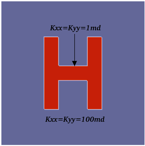
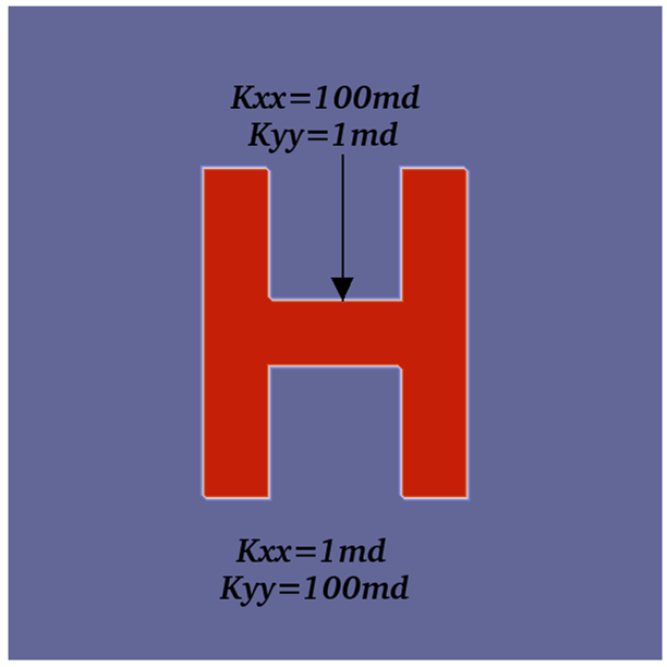
We first present results from a 2D test case (denoted as Case-1) in a horizontal layer with the permeability tensor in (1) as follows:
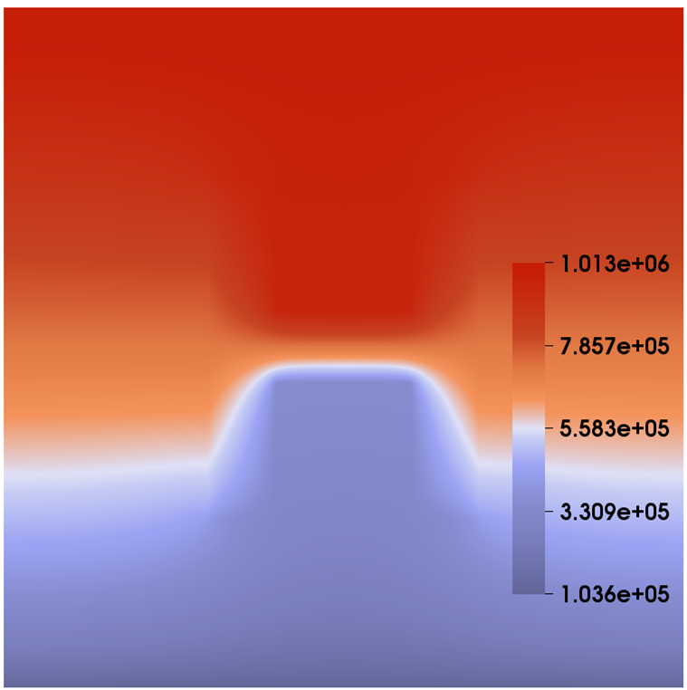
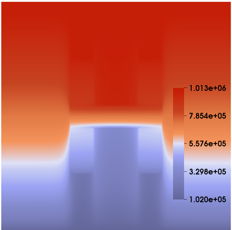
With the media being horizontal, we neglect the effect of the gravity. In the configuration, the distribution of permeabilities includes two domains with different isotropy, as shown in Figure 3. The computational domain is 100 meters long and 100 meters wide. In the simulation, we assume that the left and right boundaries of the domain are impermeable. Then we flood the system by gas from the top to the bottom, i.e., we set atm at the top boundary and set atm at the right boundary. And there is no injection/extraction inside the domain. Compared with the previous example, in this test case there is an -shape zone and the value of permeabilities has a huge jump inside and outside the zone, which brings about even greater challenges to the fully implicit solver. In the test, the simulation is performed on a mesh, the time step size is fixed to day, and the simulation is stopped at day. Figure 3 also illustrates the contour plots of the pressure. Table 1 shows the performance of the proposed fully implicit solver with respect to different permeability configurations. It is clearly seen that the simulation spends more computing time when the isotropic medium is used, which attributes to the increase in nonlinearity of the problem that affects the number of linear iterations.
| Medium type | Isotropic case | Anisotropic case |
| Average nonlinear iterations | 2.2 | 2.2 |
| Average linear iterations | 54.7 | 41.5 |
| Execution time (second) | 172.0 | 151.1 |
In the following, the experiment is conducted to simulate some 3D test cases. The focus is on the flow model with the medium being highly heterogeneous and isotropic, which significantly increases the nonlinearity of the system and imposes a severe challenge on the fully implicit solver. We first consider a 3D domain with dimension , in which the permeabilities of the porous medium are random, denoted as Case-2. The random distribution of permeability with the range [3.1,14426.2] is generated by a geostatistical model using the open source toolbox MRST [19], as shown in Figure 4. In the test, two different flow configurations are used for the injection boundary, i.e., the fixed injection pressure and the fixed injection rate. In the fixed pressure configuration, the flow with the pressure of 10 atm is injected at the part of the left-hand side ; while, for the case of the fixed injection rate, the flow is injected from the same sub-boundary with the Darcy’s velocity . The fluid flows from the right-hand side of the domain with a fixed pressure atm, and no-flow boundary conditions are imposed on the other boundaries of the domain. The initial pressure of atm is specified in the whole domain and the parameters required for this example are consistent with the previous examples.
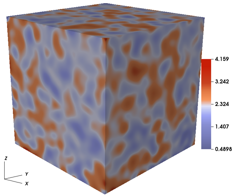
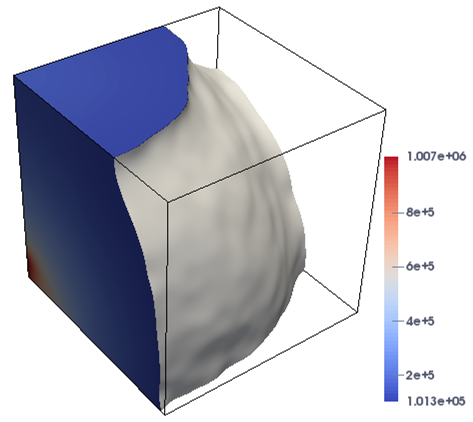
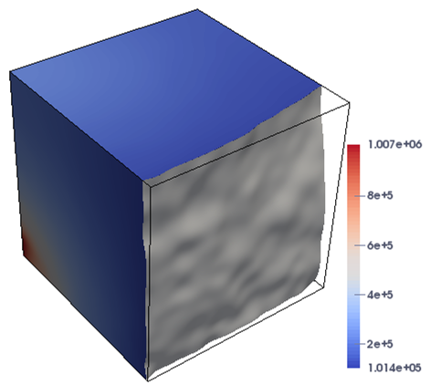
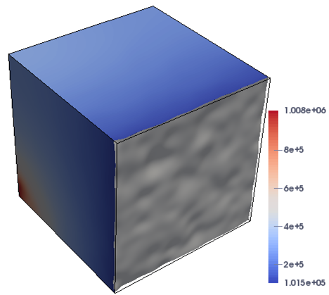
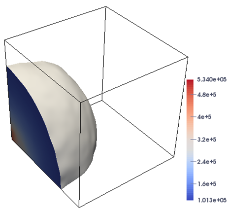
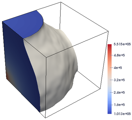
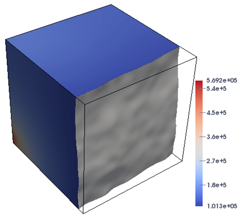
In this case, the domain is highly heterogeneous, leading to the increase in nonlinearity of the problem that is challenging for the numerical techniques. Figure 5 shows the plots of the pressure profiles for Case-2 at different times under the two flow configurations. It is demonstrated from the figures that the proposed approach successfully resolves the different stages of the simulation, and the flow is close to reach the breakthrough at the time days. In Table 2, we present the history of the values of nonlinear and linear iterations and the total execution time for the proposed solver at different times. The simulation is carried out on a mesh and the time step size is day. It can be observed from Table 2 that the number of nonlinear and linear iterations has barely changed, while the total execution time increases constantly with the advance of time as expected, which displays the robustness and effectiveness of the implicit solver to handle the highly variety of physical parameters in the model problem.
| Boundary Type | End of the simulation (day) | t=5 | |||
| Fixed pressure | Average nonlinear iterations | 3.0 | 2.9 | 2.9 | 2.9 |
| Average linear iterations | 22.6 | 23.8 | 24.3 | 24.5 | |
| Execution time (second) | 645.3 | 1095.9 | 1545.2 | 2455.6 | |
| Fixed velocity | Average nonlinear iterations | 2.8 | 2.7 | 2.7 | 2.6 |
| Average linear iterations | 24.8 | 26.3 | 27.1 | 27.9 | |
| Execution time (second) | 519.5 | 965.4 | 1325.1 | 2142.9 |
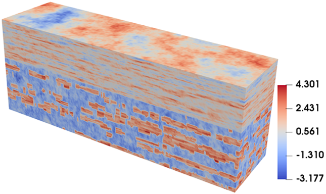
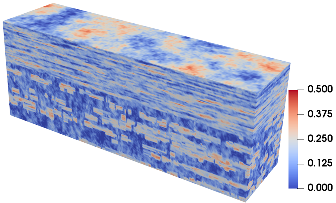
In the all of the above test cases, the porosity in the model problem (1) is assumed to a constant. In the next 3D test case (Case-3) of this subsection, we import the porosity and the permeability from the Tenth SPE Comparative Project (SPE10) [10] as an example of a realistic realization with geological and petrophysical properties, in which the porosity and the permeability are capable of variation with the change of the position. It is a classic and challenging benchmark problem for reservoir due to highly heterogeneous permeabilities and porosities. As shown in Figure 6, the permeability is characterized by variations of more than six orders of magnitude and is ranged from to , and the porosity scale ranges from 0 to 0.5. The 3D domain dimensions are 1200 ft long 2200 ft wide 170 ft thick. In the test, the boundary condition for pressure on the left-hand side of the domain is uniformly imposed to atm and on the opposite side is imposed to atm. No-flow boundary condition is set to other boundary of the domain. Other used parameters are the same as the previous case.
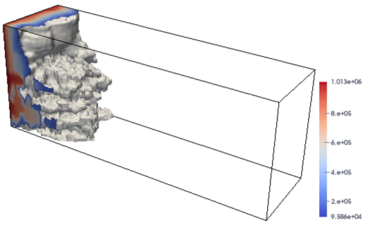
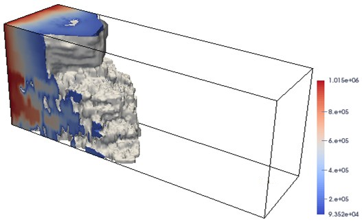
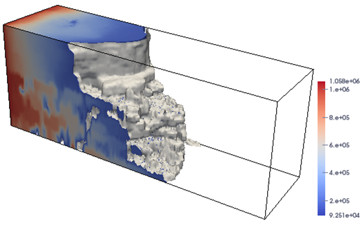
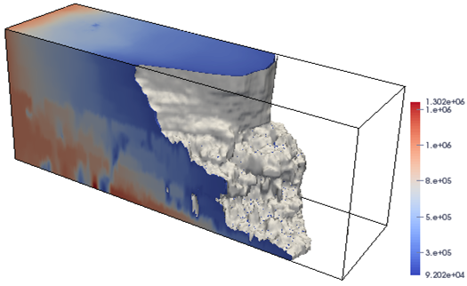
In Figure 7, we display the distributions for the pressure when the simulation is finished at different time points days. In the simulation, the mesh is and the time step size is fixed to day. The results shown in Figure 7 demonstrate that the proposed approach successfully resolves the rapid and abrupt evolution of the simulation at different stages, while keeping the solver in a robust and efficient way. Finally, we analyze the behavior of the proposed fully-implicit method when the time step size is changed. In the test, we again run the SPE-10 model on a fixed mesh. The simulation is stopped at year. The results on the average numbers of nonlinear and linear iterations as well as the total compute time are summarized in Table 3. The results in the table clearly indicate that the combination of nonlinear and linear iterations works well for even very large value of time steps. The implicit approach converges for all time steps and is unconditionally stable. In addition to that, we also notice that, as the time step size decreases, the average number of nonlinear and linear iterations become smaller, whereas the total computing time increases. This behavior is somehow expected for the fully implicit approach in a variety of applications [2, 16, 32, 35, 36].
| Time step size | 0.06 | 0.075 | 0.1 | 0.2 | 0.3 |
| Number of time steps | 50 | 40 | 30 | 15 | 10 |
| Average nonlinear iterations | 3.5 | 3.6 | 3.8 | 4.4 | 4.5 |
| Average linear iterations | 45.4 | 49.3 | 52.1 | 67.5 | 80.0 |
| Execution time (second) | 1424.2 | 1191.7 | 951.4 | 579.8 | 408.8 |
4.2 Performance of Schwarz preconditioners
In this subsection, we focus on the parallel performance of the proposed fully implicit solver with respect to the one-level or multilevel Schwarz preconditioner by Case-1, Case-2, and a new 3D test case. In the new 3D case, denoted as Case-4, the computational domain is with the medium being heterogeneous and isotropic, and the distribution of permeability in each layer is the same as the distribution of Case-1. We flood the system by gas from the behind face (, , ) to the front face, i.e., we set atm at the behind face and set atm at the front face. And there is no injection/extraction inside the domain.
In the test, we use the following stopping parameters and notations, unless specified otherwise. The relative and absolute tolerances in (15) for Newton iterations are set to and , respectively. The linear systems are solved by the one-level or two-level Schwarz preconditioned GMRES method with absolute and relative tolerances of and in (14), except for the coarse solve of the two-level preconditioner, for which we use as the relative stopping tolerance. The restart value of the GMRES method is fixed as 30. In the tables of the following tests, the symbol “” denotes the number of processor cores that is the same as the number of subdomains, “N. It” stands for the average number of Newton iterations per time step, “L. It” the average number of the one-level or two-level Schwarz preconditioned GMRES iterations per Newton iteration, and “Time” the total computing time in seconds.
4.2.1 One-level Schwarz preconditioners
Under the framework of one-level Schwarz preconditioners, we study the performance of the fully implicit solver, when different types of the additive Schwarz preconditioners are employed and several important parameters such as the subdomain solver and the overlapping size are taken into consideration.
We first look at the influence of subdomain solvers. In this test, we focus on the classical AS preconditioner (17) and fix the overlapping factor to . The ILU factorization with different levels of fill-in and the full LU factorization are considered for the subdomain solvers. The simulation of Case-1 is applied to a fixed mesh using processors. The time step size is 0.1 day, and we run the 2D case for the first 20 time steps. The simulation of Case-4 is applied to a fixed mesh by using processors. The time step size is 0.1 day, and we run this case for the first 10 time steps. The numerical results are summarized in Table 4. We observe from the table that the number of nonlinear iterations is not sensitive to the choice of subdomain solvers. The linear system converges with less iterations when the LU factorization method is used as the subdomain solver; while the ILU approach is beneficial to the AS preconditioner in terms of the computing time, especially for the 3D test case.
| Case | Case-1 | Case-4 | ||||
| Solver | N. It | L. It | Time | N. It | L. It | Time |
| LU | 3.0 | 52.9 | 37.1 | 4.2 | 32.9 | 954.8 |
| ILU(0) | 3.0 | 99.1 | 34.3 | 4.3 | 161.7 | 282.4 |
| ILU(1) | 3.0 | 75.7 | 29.9 | 4.3 | 98.0 | 253.0 |
| ILU(2) | 3.0 | 73.9 | 32.1 | 4.3 | 76.1 | 239.6 |
| ILU(4) | 3.0 | 66.2 | 33.8 | 4.3 | 51.0 | 245.8 |
Moreover, in Table 5, we also compare the impact of different subdomain solvers for Case-2, when the fixed pressure and velocity boundaries are imposed for the flow configurations. In the test, the simulation is carried out on a mesh and the time step size is fixed to day by using processors. It is clearly illustrated from the results that the choice of ILU(2) is still optimal for the 3D flow problem under the random permeability case with different boundary conditions, when the flow undergoes different stages in the complex simulation as shown in Figure 5.
| Solver | t=1 | t=2 | t=3 | t=5 | ||||||||
| Model-A | N. It | L. It | Time | N. It | L. It | Time | N. It | L. It | Time | N. It | L. It | Time |
| LU | 3.0 | 33.0 | 685.2 | 2.9 | 36.6 | 1167.0 | 2.9 | 38.7 | 1652.7 | 2.9 | 41.2 | 2625.9 |
| ILU(0) | 3.0 | 161.5 | 435.3 | 2.9 | 183.0 | 760.1 | 2.9 | 195.3 | 1086.8 | 2.9 | 208.3 | 1742.7 |
| ILU(1) | 3.0 | 100.6 | 415.5 | 2.9 | 110.3 | 715.9 | 2.9 | 116.4 | 1015.4 | 2.9 | 123.6 | 1616.7 |
| ILU(2) | 3.0 | 80.0 | 403.4 | 2.9 | 88.9 | 695.0 | 2.9 | 93.3 | 991.1 | 2.9 | 98.4 | 1572.5 |
| ILU(4) | 3.0 | 52.4 | 417.8 | 2.9 | 58.8 | 725.1 | 2.9 | 62.1 | 1030.5 | 2.9 | 65.7 | 1638.9 |
| Model-B | N. It | L. It | Time | N. It | L. It | Time | N. It | L. It | Time | N. It | L. It | Time |
| LU | 2.8 | 39.3 | 563.7 | 2.7 | 42.9 | 1046.9 | 2.7 | 45.2 | 1438.8 | 2.6 | 47.7 | 2335.0 |
| ILU(0) | 2.8 | 178.5 | 366.0 | 2.7 | 190.4 | 679.2 | 2.7 | 201.8 | 934.4 | 2.6 | 214.9 | 1518.6 |
| ILU(1) | 2.8 | 113.9 | 349.6 | 2.7 | 124.0 | 641.3 | 2.7 | 131.6 | 873.7 | 2.6 | 138.4 | 1408.2 |
| ILU(2) | 2.8 | 87.8 | 340.2 | 2.7 | 95.7 | 626.8 | 2.7 | 101.2 | 859.0 | 2.6 | 105.0 | 1363.8 |
| ILU(4) | 2.8 | 67.3 | 351.8 | 2.7 | 74.1 | 650.5 | 2.7 | 78.5 | 895.2 | 2.6 | 81.6 | 1455.1 |
We then perform test with the 2D and 3D test cases by varying the combination of the overlapping factor and the Schwarz preconditioner types, i.e., the classical-AS (17), the left-RAS (18), and the right-RAS (19) preconditioners. Based on the above observations, we take the choice of the subdomain solver with ILU(1) for the 2D test case and ILU(2) for the 3D test case. The numbers of nonlinear and linear iterations together with the execution time are illustrated in Table 6. The results in the table suggest that the more robust combination is the left-RAS preconditioner with the overlapping size for the compromise between the linear iteration and the total computing time. We remark that, when the overlapping size , these preconditioners degenerates into the block-Jacobi preconditioner.
| Case | Case-1 | Case-2 | Case-4 | |||||||
| Preconditioner | N. It | L. It | Time | N. It | L. It | Time | N. It | L. It | Time | |
| Classical-AS | 0 | 3.0 | 80.4 | 31.5 | 2.8 | 73.9 | 321.6 | 4.2 | 53.0 | 211.9 |
| 1 | 3.0 | 75.7 | 29.9 | 2.8 | 87.8 | 340.2 | 4.3 | 76.1 | 239.6 | |
| 2 | 3.0 | 76.9 | 31.8 | 2.8 | 99.1 | 352.7 | 4.3 | 92.6 | 286.7 | |
| 3 | 3.0 | 76.8 | 32.5 | 2.8 | 103.4 | 368.2 | 4.3 | 93.8 | 326.6 | |
| Left-RAS | 1 | 3.0 | 55.8 | 28.3 | 2.8 | 43.7 | 306.2 | 4.2 | 37.5 | 205.0 |
| 2 | 3.0 | 51.9 | 28.8 | 2.8 | 41.6 | 312.8 | 4.3 | 34.0 | 218.0 | |
| 3 | 3.0 | 49.4 | 28.9 | 2.8 | 40.8 | 322.5 | 4.3 | 33.2 | 232.3 | |
| Right-RAS | 1 | 3.0 | 55.6 | 28.2 | 2.8 | 44.5 | 307.5 | 4.3 | 37.1 | 207.3 |
| 2 | 3.0 | 51.4 | 28.0 | 2.8 | 42.0 | 311.4 | 4.3 | 34.3 | 215.8 | |
| 3 | 3.0 | 48.7 | 28.0 | 2.8 | 41.2 | 326.2 | 4.3 | 33.4 | 223.4 | |
4.2.2 Two-level Schwarz preconditioners
For the reservoir simulation with high accuracy, the supercomputer with a large number of processors is a must, and therefore the scalabilities of the algorithm with respect to the number of processors are critically important. As introduced in Section 3, in the one-level Schwarz preconditioner, the average number of linear iterations per Newton iteration grows with the number of processors , resulting in the deterioration of the implicit solver. It is clear that some stabilization is needed, which is achieved by the two-level method with the use of a coarse mesh and the interpolation operators explained in Section 3. The performance of the two-level method depends heavy on the two linear solvers defined on the coarse and fine meshes. Here, we restrict ourselves within the framework of Schwarz preconditioned GMRES methods, i.e., we refer to these iterative methods as smoothers on the each levels.
There are several assembly techniques available to construct a hybrid two-level Schwarz preconditioner by composing the one-level additive Schwarz preconditioner with a coarse-level preconditioner in a multiplicative or additive manner. Choosing the right type of two-level Schwarz preconditioners is very important for the overall performance of the preconditioner. A large number of numerical experiments is often necessary to identify the right selection. As introduced in Section 3, in the study we investigate the pure-coarse (27), the additive (26), the left-Kaskade (24), the right-Kaskade (25), and the V-cycle type (23) two-level Schwarz preconditioners. For each numerical case, the the overlapping sizes on the fine and coarse levels are fixed to and , respectively. The subdomain solvers on the fine and coarse levels is solved by the LU factorization. In the test, we again run the 2D model with a fixed time step size day on a mesh and run Case-4 with a fixed time step size day on a mesh, and the simulation is finished at and days, respectively. For the simulation of Case-4, the flow problem with the fixed velocity model is solved on a mesh, and the computation is ended at day with day. The coarse-to-fine mesh ratio is used to in each direction. In Table 7, we report the performance of the proposed two-level Schwarz preconditioners with respect to different interpolation operators that includes the first-order scheme (29), the second-order scheme (30), and the third-order scheme (31). Below we list the observations made from the results.
-
(a)
We know that the effectiveness of the Schwarz preconditioner relies on its ability to mimic the spectrum of the linear operator and at the same time is relatively cheap to apply. We see that using the high order schemes in the construction of the Schwarz preconditioner provides less linear iteration counts. Moreover, when compared with the Schwarz method with high order methods, the low order approach is more attractive in the terms of the execution time, owing to its lower bandwidth and a less number of nonzeros in the sparse matrix. The results in the table suggest that the second order scheme is a suitable choice for compromise between the iterations and the total computing time.
-
(b)
The best choices for some of the options in the multilevel Schwarz preconditioner are problem dependent. For the implicit solution of subsurface flows problems, from Table 7, we can see that the additive or Kaskade type two-level Schwarz preconditioners is exacerbated by a larger number of outer linear iterations, when compared with the V-cycle approach. The pure coarse version of the two-level approach performs considerably worse than the hybrid methods. Hence, our experiments suggest that there is a benefit to include both pre- and post-swipes of the one-level preconditioning for the simulation of model problems, especially for the 3D test cases.
| Case | Type | First-order | Second-order | Third-order | ||||||
| N. It | L. It | Time | N. It | L. It | Time | N. It | L. It | Time | ||
| Case-1 | Coarse | – | – | – | – | – | – | – | – | – |
| Additive | 3.0 | 114.6 | 233.9 | 3.0 | 71.3 | 207.3 | 3.0 | 45.9 | 734.7 | |
| Left-Kaskade | 3.0 | 71.1 | 204.2 | 3.0 | 34.1 | 163.9 | 3.0 | 8.05 | 565.2 | |
| Right-Kaskade | 3.0 | 75.0 | 194.8 | 3.0 | 37.7 | 157.8 | 3.0 | 9.03 | 565.5 | |
| V-Cycle | 3.0 | 10.0 | 129.6 | 3.0 | 9.4 | 129.1 | 3.0 | 5.4 | 579.3 | |
| Case-2 | Coarse | – | – | – | – | – | – | – | – | – |
| Additive | 2.8 | 87.4 | 371.0 | 2.8 | 58.3 | 349.4 | 2.8 | 42.0 | 5186.7 | |
| Left-Kaskade | 2.8 | 31.3 | 325.7 | 2.8 | 20.6 | 312.4 | 2.8 | 14.7 | 4921.4 | |
| Right-Kaskade | 2.8 | 34.5 | 326.6 | 2.8 | 21.8 | 315.9 | 2.8 | 15.1 | 4940.3 | |
| V-Cycle | 2.8 | 14.9 | 314.2 | 2.8 | 12.6 | 308.8 | 2.8 | 5.8 | 4770.9 | |
| Case-4 | Coarse | – | – | – | – | – | – | – | – | – |
| Additive | 4.0 | 79.9 | 453.2 | 4.0 | 44.5 | 402.1 | 4.0 | 36.6 | 6114.6 | |
| Left-Kaskade | – | – | – | – | – | – | 4.0 | 13.4 | 5763.8 | |
| Right-Kaskade | – | – | – | – | – | – | 4.0 | 14.8 | 5308.8 | |
| V-Cycle | 4.0 | 11.4 | 374.2 | 4.0 | 10.3 | 372.8 | 4.0 | 5.1 | 5156.5 | |
For the two-level preconditioner, the size of the coarse mesh has a strong impact on the efficiency and robustness of the method. It is clear that using a relatively fine coarse mesh gains a stronger two-level Schwarz preconditioner, and therefore it can help reduce the total number of linear iterations. On the other hand, finer coarse meshes generates plenty of amount of memory and cache, leading to the increase of the total compute time. An important implementation detail to consider in designing the two-level method is to balance the effects of preconditioning and the computing time of the coarse solve. To understand the impact of different coarse meshes on the convergence of the algorithm, we show the results with different coarse mesh sizes with respect to different interpolation operators for the 2D and 3D test cases. In the test, the fine meshes for the 2D and 3D problems are and , respectively. As shown in Table 8, we observe from the table that: (a) for the first-order scheme, the bad quality of the second coarse mesh does lead to a large increase of the number of iterations; (b) with the help of higher order schemes, the linear iterations increase slowly with growth of coarse-to-fine mesh ratios. This implies that a higher order scheme does a good job on preconditioning the fine mesh problem, since the second coarse mesh even with worse quality is able to keep the whole algorithm efficient in terms of the number of iterations.
| Case | Mesh ratio | First-order | Second-order | Third-order | ||||||
| N. It | L. It | Time | N. It | L. It | Time | N. It | L. It | Time | ||
| Case-1 | 2 | 3.0 | 10.0 | 129.6 | 3.0 | 9.4 | 129.1 | 3.0 | 5.4 | 579.3 |
| 4 | 3.0 | 18.8 | 123.0 | 3.0 | 16.9 | 120.9 | 3.0 | 13.3 | 553.1 | |
| 8 | 3.0 | 26.8 | 130.1 | 3.0 | 19.2 | 120.0 | 3.0 | 14.1 | 535.5 | |
| 16 | 3.0 | 36.0 | 140.5 | 3.0 | 19.5 | 118.5 | 3.0 | 14.2 | 532.8 | |
| Case-2 | 2 | 2.8 | 14.9 | 314.2 | 2.8 | 12.6 | 308.8 | 2.8 | 5.8 | 4770.9 |
| 4 | 2.8 | 16.2 | 310.7 | 2.8 | 13.1 | 303.1 | 2.8 | 8.9 | 4741.6 | |
| 8 | 2.8 | 18.9 | 308.5 | 2.8 | 13.7 | 299.6 | 2.8 | 9.4 | 4725.3 | |
| 16 | 2.8 | 30.4 | 326.2 | 2.8 | 15.8 | 302.4 | 2.8 | 11.3 | 4709.2 | |
| Case-4 | 2 | 4.0 | 11.4 | 374.2 | 4.0 | 10.3 | 372.8 | 4.0 | 5.1 | 5156.5 |
| 4 | 4.0 | 17.7 | 372.1 | 4.0 | 10.6 | 368.4 | 4.0 | 9.5 | 5106.9 | |
| 8 | 4.0 | 18.8 | 370.2 | 4.0 | 11.0 | 354.4 | 4.0 | 10.2 | 5091.3 | |
| 16 | 4.0 | 39.8 | 415.7 | 4.0 | 12.7 | 356.3 | 4.0 | 11.6 | 5051.4 | |
4.3 Parallel scalability
Achieving good parallel scalability is important in parallel computing, especially when solving large-scale problems with many processors. Hence, in the following we focus on the parallel performance of the proposed fully implicit method with one-level and two-level restricted additive Schwarz preconditioners. Again, the 2D and 3D test problems descried in subsectionn 4.2 are used for the scalability simulations. The numerical tests are carried out on the Tianhe-2 supercomputer. The computing nodes of Tianhe-2 are interconnected via a proprietary high performance network, and there are two 12-core Intel Ivy Bridge Xeon CPUs and 24 GB local memory in each node. In the numerical experiments, we use all 24 CPU cores in each node and assign one subdomain to each core.
| Case | Mesh | One-level | Two-level | |||||
| N. It | L. It | Time | N. It | L. It | Time | |||
| Case-1 | 256 | 7.2 | 65.4 | 564.3 | 7.2 | 18.3 | 460.7 | |
| 512 | 7.2 | 95.0 | 291.5 | 7.2 | 18.9 | 187.6 | ||
| 1024 | 7.2 | 96.3 | 136.6 | 7.2 | 19.6 | 90.0 | ||
| 2048 | 7.2 | 142.1 | 82.1 | 7.2 | 20.4 | 46.1 | ||
| 4096 | 7.2 | 144.4 | 44.9 | 7.2 | 21.1 | 26.3 | ||
| 8192 | 7.2 | 214.2 | 34.6 | 7.2 | 24.0 | 18.8 | ||
| Case-4 | 512 | 7.8 | 82.7 | 775.7 | 7.8 | 31.0 | 735.1 | |
| 1024 | 7.8 | 97.7 | 250.1 | 7.8 | 35.2 | 231.5 | ||
| 2048 | 7.8 | 109.8 | 97.6 | 7.8 | 37.9 | 76.2 | ||
| 4096 | 7.8 | 122.9 | 68.7 | 7.8 | 43.2 | 37.6 | ||
| 8192 | 7.8 | 147.0 | 29.9 | 7.8 | 35.0 | 21.8 | ||
The strong scalability (denoted by ) and the parallel efficiency (denoted by ) are respectively defined as follows:
where denotes the smallest processors number of the compassion, denotes computational time with processors. In the strong scalability test of the 2D problem, we use a fixed mesh , and also fixed time step sizes and 0.01 days, in which the largest simulation consists of degrees of freedom. Moreover, we investigate the scalability of the the proposed fully implicit solver by using the fixed mesh , also a fixed time step size day for Case-4. The number of processors is changed from to . Table 9 shows the number of nonlinear and linear iterations as well as the computing time with respect to the number of processors, and Figure 8 provides the compute time and curve for the strong scalability. The table clearly indicates that the number of Newton iterations remains to be independent of the number of processors, and the number of linear iterations depends on the preconditioner employed in the solver. For the one-level solver, the number of linear iterations suffers as the number of processors increases. While, with the help of the coarse mesh, the number of linear iterations for the two-level preconditioner is kept to a low level as the number of processors increases. Moreover, to investigate the strong scalability of the proposed method with respect to the heterogeneity property in the reservoir, we again use the Case-2 benchmark, and compare the number of nonlinear and linear iterations and the total computing time at days, respectively. As shown in Table 10, a good strong scalability is also achieved for the random case test under longer simulations.


| Level | t=1 | t=2 | t=3 | t=5 | |||||||||
| N. It | L. It | Time | N. It | L. It | Time | N. It | L. It | Time | N. It | L. It | Time | ||
| One | 64 | 2.8 | 44.5 | 307.5 | 2.7 | 52.1 | 588.6 | 2.7 | 58.7 | 801.4 | 2.6 | 63.5 | 1275.7 |
| 128 | 2.8 | 53.7 | 125.2 | 2.7 | 64.8 | 245.2 | 2.7 | 69.3 | 353.2 | 2.6 | 75.2 | 583.1 | |
| 256 | 2.8 | 63.1 | 57.8 | 2.7 | 71.6 | 110.9 | 2.7 | 80.1 | 169.6 | 2.6 | 84.9 | 252.7 | |
| 512 | 2.8 | 72.6 | 28.3 | 2.7 | 81.2 | 52.6 | 2.7 | 87.7 | 80.2 | 2.6 | 92.5 | 134.9 | |
| 1024 | 2.8 | 84.9 | 18.9 | 2.7 | 94.5 | 37.2 | 2.7 | 99.4 | 58.5 | 2.6 | 104.7 | 96.3 | |
| 2048 | 2.8 | 92.5 | 12.4 | 2.7 | 106.7 | 28.5 | 2.7 | 112.8 | 39.1 | 2.6 | 118.5 | 62.5 | |
| Two | 64 | 2.8 | 18.8 | 283.6 | 2.7 | 20.2 | 554.7 | 2.7 | 22.6 | 772.0 | 2.6 | 24.3 | 1236.8 |
| 128 | 2.8 | 21.5 | 104.5 | 2.7 | 24.5 | 218.1 | 2.7 | 27.3 | 312.4 | 2.6 | 29.7 | 545.9 | |
| 256 | 2.8 | 25.8 | 42.6 | 2.7 | 28.9 | 91.5 | 2.7 | 30.6 | 137.9 | 2.6 | 33.5 | 227.5 | |
| 512 | 2.8 | 29.4 | 22.8 | 2.7 | 31.7 | 46.5 | 2.7 | 34.3 | 74.1 | 2.6 | 36.4 | 118.4 | |
| 1024 | 2.8 | 32.3 | 15.7 | 2.7 | 35.4 | 32.9 | 2.7 | 36.8 | 51.8 | 2.6 | 38.2 | 89.2 | |
| 2048 | 2.8 | 37.6 | 11.0 | 2.7 | 39.2 | 25.3 | 2.7 | 40.2 | 35.7 | 2.6 | 42.5 | 58.3 | |
The weak scalability is used to examine how the execution time varies with the number of processors when the problem size per processor is fixed. In the weak scaling test, we start with a small mesh with the number of processors and end up with a large mesh ( degrees of freedom) using up to processor cores for the 2D test case. Also, we further test our algorithms in terms of the weak scalability starting with a mesh and for Case-4. We refine the mesh and increase the number of processors simultaneously to keep the number of unknowns per processor as a constant. Table 11 presents the results of weak scaling tests, which are run with fixed time step sizes and 0.5 days respectively, and are stopped after implicit time steps, i.e., the simulation are terminated at and days. We observe that, with the increase of the number of processors form to and to for the 2D and 3D test problems, a reasonably good weak scaling performance is obtained, especially for the two-level restricted Schwarz approach, which indicates that the proposed solver has a good weak scalability for this range of processor counts.
| Case | Mesh | One-level | Two-level | |||||
| N. It | L. It | Time | N. It | L. It | Time | |||
| Case-1 | 64 | 3.8 | 26.4 | 37.4 | 3.8 | 12.7 | 35.2 | |
| 256 | 4.8 | 46.4 | 61.1 | 4.8 | 18.0 | 54.3 | ||
| 576 | 6.2 | 69.5 | 95.1 | 6.2 | 14.4 | 67.2 | ||
| 1024 | 7.2 | 96.3 | 136.6 | 7.2 | 19.6 | 90.0 | ||
| 2304 | 9.8 | 173.9 | 316.8 | 9.8 | 17.8 | 131.8 | ||
| 4096 | 12.4 | 294.7 | 607.8 | 12.4 | 17.0 | 197.1 | ||
| Case-4 | 216 | 3.8 | 40.6 | 12.5 | 3.8 | 16.9 | 10.7 | |
| 512 | 4.2 | 56.3 | 15.0 | 4.2 | 15.9 | 12.2 | ||
| 1728 | 5.8 | 90.3 | 27.6 | 5.8 | 35.9 | 22.5 | ||
| 2744 | 6.8 | 107.7 | 35.2 | 6.8 | 38.2 | 28.1 | ||
| 4096 | 7.8 | 122.9 | 68.7 | 7.8 | 43.2 | 37.6 | ||
| 6859 | 9.4 | 147.4 | 85.9 | 9.4 | 44.7 | 54.6 | ||
In summary, observing from the above tables and the figures, we highlight that, compared with the one-level method, the two-level restricted additive Schwarz method results in a very sharp reduction in the number of linear iterations and therefore brings about a good reduction in compute time. Hence, the two-level method is much more effective and scalable than the one-level approach in terms of the strong and weak scalabilities.
5 Conclusions
The simulation of subsurface flows with high resolution solutions is of paramount importance in reservoir simulation. In this work, we have presented a parallel fully implicit framework based on multilevel restricted Schwarz preconditioners for subsurface flow simulations with Peng-Robinson equation of state. The proposed framework can get rid of the restriction of the time step size, and is flexible and allows us to construct different type of multilevel preconditioners, based on plenitudinous choices for additively or multiplicatively strategies, interpolation and restriction operators. After experimenting with many different overlapping Schwarz type preconditioners, we found that the class of V-cycle-type restricted Schwarz methods based on the second order scheme is extremely beneficial for the problems under investigation. Numerical experiments also showed that the proposed algorithms and simulators are robust and scalable for the large-scale solution of some benchmarks as well as realistic problems with highly heterogeneous permeabilities in petroleum reservoirs.
Acknowledgment
The authors would like to express their appreciations to the anonymous reviewers for the invaluable comments that have greatly improved the quality of the manuscript.
References
- [1] S. Balay, J. Brown, K. Buschelman, V. Eijkhout, W. Gropp, D. Kaushik, M. Knepley, L.C. McInnes, B.F. Smith, H. Zhang, PETSc Users Manual, Argonne National Laboratory, 2019.
- [2] Q.M. Bui, H.C. Elman, J.D. Moulton, Algebraic multigrid preconditioners for multiphase flow in porous media, SIAM J. Sci. Comput. 39 (2017) S662–S680.
- [3] Q.M. Bui, L. Wang, D. Osei-Kuffuor, Algebraic multigrid preconditioners for two-phase flow in porous media with phase transitions, Adv. Water Resour. 114 (2018) 19–28.
- [4] X.-C. Cai, M. Dryja, M. Sarkis, Restricted additive Schwarz preconditioners with harmonic overlap for symmetric positive definite linear systems, SIAM J. Numer. Anal. 41 (2003) 1209–1231.
- [5] X.-C. Cai, W.D. Gropp, D. E. Keyes, R. G. Melvin, D. P. Young, Parallel Newton–Krylov–Schwarz algorithms for the transonic full potential equation, SIAM J. Sci. Comput. 19 (1998) 246–265.
- [6] X.-C. Cai, M. Sarkis, A restricted additive Schwarz preconditioner for general sparse linear systems, SIAM J. Sci. Comput. 21 (1999) 792–797.
- [7] X.-C. Cai, D.E. Keyes, Nonlinearly preconditioned inexact Newton algorithms, SIAM J. Sci. Comput. 24 (2002)183–200.
- [8] Z. Chen, G. Huan, Y. Ma, Computational Methods for Multiphase Flows in Porous Media, SIAM, Philadelphia, PA, 2006.
- [9] Z. Chen, Reservoir Simulation: Mathematical Techniques in Oil Recovery, SIAM, Philadelphia, PA, 2007.
- [10] M. Christie, M. Blunt, Tenth SPE comparative solution project: A comparison of upscaling techniques. In SPE Reservoir Simulation Symposium. Society of Petroleum Engineers. (2001) 308–317.
- [11] C.N. Dawson, H. Klíe, M.F. Wheeler, C.S. Woodward, A parallel, implicit, cell-centered method for two-phase flow with a preconditioned Newton–Krylov solver, Computat. Geosci. 1 (1997) 215–249.
- [12] J.E. Dennis, R.B. Schnabel, Numerical Methods for Unconstrained Optimization and Nonlinear Equations, SIAM, Philadelphia, 1996.
- [13] A. Firoozabadi, Thermodynamics of Hyrocarbon Reservoirs, McGraw-Hill, New York, 1999.
- [14] J.B. Haga, H. Osnes, H.P. Langtangen, A parallel block preconditioner for large-scale poroelasticity with highly heterogeneous material parameters, Comput. Geosci. 16 (2012) 723–734.
- [15] D.A. Knoll, D.E. Keyes, Jacobian-free Newton–Krylov methods: a survey of approaches and applications, J. Comput. Phys. 193 (2004) 357–397.
- [16] F. Kong, X.-C. Cai, A highly scalable multilevel Schwarz method with boundary geometry preserving coarse spaces for 3D elasticity problems on domains with complex geometry, SIAM J. Sci. Comput. 38 (2016) C73–C95.
- [17] S. Lacroix, Y.V. Vassilevski, J.A. Wheeler, M.F. Wheeler, Iterative solution methods for modeling multiphase flow in porous media fully implicitly, SIAM J. Sci. Comput. 25 (2003) 905–926.
- [18] J.J. Lee, K.-A. Mardal, R. Winther, Parameter-robust discretization and preconditioning of biot’s consolidation model, SIAM J. Sci. Comput. 39 (2017) A1–A24.
- [19] K. Lie, S. Krogstad, I. Ligaarden, J. Natvig, H. Nilsen, B. Skaflestad, Open-source MATLAB implementation of consistent discretisations on complex grids, Comput. Geosci. 16 (2012) 297–322.
- [20] L. Liu, D.E. Keyes, R. Krause, A note on adaptive nonlinear preconditioning techniques, SIAM J. Sci. Comput. 40 (2018) A1171–A1186.
- [21] Y. Liu, H. Yang, Z. Xie, P. Qin, R. Li, Parallel simulation of variably saturated soil water flows by fully implicit domain decomposition methods, J. Hydrol. 582 (2020) 124481.
- [22] J.E.P. Monteagudo, A. Firoozabadi, Comparison of fully implicit and IMPES formulations for simulation of water injection in fractured and unfractured media, Int. J. Numer. Meth. Engng. 69 (2007) 698–728.
- [23] E.E. Prudencio, X.-C. Cai, Parallel multilevel restricted Schwarz preconditioners with pollution removing for PDE-constrained optimization, SIAM J. Sci. Comput. 29 (2007) 964–985.
- [24] C. Qiao, S. Wu, J. Xu, C.S. Zhang, Analytical decoupling techniques for fully implicit reservoir simulation. J. Comput. Phys. 336 (2017) 664–681.
- [25] Y. Saad, Iterative Methods for Sparse Linear Systems. SIAM, Second ed., 2003.
- [26] J.O. Skogestad, E. Keilegavlen, J.M. Nordbotten, Domain decomposition strategies for nonlinear flow problems in porous media, J. Comput. Phys. 234 (2013) 439–451.
- [27] G. Singh , M.F. Wheeler, A space-time domain decomposition approach using enhanced velocity mixed finite element method, J. Comput. Phys. 374 (2018) 893–911.
- [28] B. Smith, P. Bjørstad, W. Gropp, Domain Decomposition: Parallel Multilevel Methods for Elliptic Partial Differential Equations, Cambridge University Press, 1996.
- [29] A. Toselli, O. Widlund, Domain Decomposition Methods-Algorithms and Theory, Springer, Berlin, 2005.
- [30] J.R. Wallis, Incomplete gaussian elimination as a preconditioning for generalized conjugate gradient acceleration, in SPE Reservoir Simulation Symposium, Society of Petroleum Engineers, 1983.
- [31] J.R. Wallis, R.P. Kendall, L.E. Little, Constrained residual acceleration of conjugate residual methods, in SPE Reservoir Simulation Symposium, Society of Petroleum Engineers, 1985.
- [32] K. Wang, H. Liu, Z. Chen, A scalable parallel black oil simulator on distributed memory parallel computers, J. Comput. Phys. 301 (2015) 19–34.
- [33] J.A. White, N. Castelletto, H.A. Tchelepi, Block-partitioned solvers for coupled poromechanics: A unified framework, Comput. Methods Appl. Mech. Engrg. 303 (2016) 55–74.
- [34] H. Yang, F.-N. Hwang, X.-C. Cai, Nonlinear preconditioning techniques for full-space Lagrange-Newton solution of PDE-constrained optimization problems, SIAM J. Sci. Comput. 38 (2016) A2756–A2778.
- [35] H. Yang, Y. Li, S. Sun, Nonlinearly preconditioned constraint-preserving algorithms for subsurface three-phase flow with capillarity, Comput. Methods Appl. Mech. Engrg. 367 (2020) 113140.
- [36] H. Yang, S. Sun, Y. Li, C. Yang, A scalable fully implicit framework for reservoir simulation on parallel computers, Comput. Methods Appl. Mech. Engrg. 330 (2018) 334–350.
- [37] H. Yang, S. Sun, Y. Li, C. Yang, A fully implicit constraint-preserving simulator for the black oil model of petroleum reservoirs, J. Comput. Phys. 396 (2019) 347–363.
- [38] H. Yang, S. Sun, C. Yang, Nonlinearly preconditioned semismooth Newton methods for variational inequality solution of two-phase flow in porous media, J. Comput. Phys. 332 (2017) 1–20.
- [39] H. Yang, C. Yang, S. Sun, Active-set reduced-space methods with nonlinear elimination for two-phase flow problems in porous media, SIAM J. Sci. Comput. 38 (2016) B593–B618.