This paper was converted on www.awesomepapers.org from LaTeX by an anonymous user.
Want to know more? Visit the Converter page.

Optimal Control of Multi-Agent Systems
with Processing Delays

Mruganka Kashyap M. Kashyap is with the Department of Electrical and Computer Engineering at
Northeastern University, Boston, MA 02115, USA. (e-mail: [email protected]).
   Laurent Lessard L. Lessard is with the Department of Mechanical and Industrial Engineering at
Northeastern University, Boston, MA 02115, USA. (e-mail: [email protected]).
Abstract

In this article, we consider a cooperative control problem involving a heterogeneous network of dynamically decoupled continuous-time linear plants. The (output-feedback) controllers for each plant may communicate with each other according to a fixed and known transitively closed directed graph. Each transmission incurs a fixed and known time delay. We provide an explicit closed-form expression for the optimal decentralized controller and its associated cost under these communication constraints and standard linear quadratic Gaussian (LQG) assumptions for the plants and cost function. We find the exact solution without discretizing or otherwise approximating the delays. We also present an implementation of each sub-controller that is efficiently computable, and is composed of standard finite-dimensional linear time-invariant (LTI) and finite impulse response (FIR) components, and has an intuitive observer-regulator architecture reminiscent of the classical separation principle.

1 Introduction

In multi-agent systems such as swarms of unmanned aerial vehicles, it may be desirable for agents to cooperate in a decentralized fashion without receiving instructions from a central coordinating entity. Each agent takes local measurements, performs computations, and may communicate its measurements with a given subset of the other agents, with a time delay. In this article, we investigate the problem of optimal control under the aforementioned communication constraints.

We model each agent as a continuous-time linear time-invariant (LTI) system. We make no assumption of homogeneity across agents; each agent may have different dynamics. We assume the aggregate dynamics of all agents are described by the state-space equations

[x˙zy]=[AB1B2C10D12C2D210][xwu],\begin{bmatrix}\dot{x}\\ z\\ y\end{bmatrix}=\begin{bmatrix}A&B_{1}&B_{2}\\ C_{1}&0&D_{12}\\ C_{2}&D_{21}&0\end{bmatrix}\begin{bmatrix}x\\ w\\ u\end{bmatrix}, (1)

where xx is the global state, zz is the regulated output, yy is the measured output, ww is the exogenous disturbance, and uu is the controlled input. The decoupled nature of the agents imposes a sparsity structure on the plant. Namely, if we partition xx, yy, ww, uu each into NN pieces corresponding to the NN agents, the conformally partitioned state space matrices AA, B1B_{1}, B2B_{2}, C2C_{2}, D21D_{21} are block-diagonal. The regulated output zz, however, couples all agents’ states and inputs, so in general C1C_{1} and D12D_{12} will be dense. The matrix transfer function (w,u)(z,y)(w,u)\to(z,y) is a standard four-block plant that takes the form111In a slight abuse of notation, the vectors zz, yy, ww, and uu now refer to the Laplace transforms of the corresponding time-domain signals in (1).

[zy]=[𝒫11(s)𝒫12(s)𝒫21(s)𝒫22(s)][wu],\begin{bmatrix}z\\ y\end{bmatrix}=\begin{bmatrix}\mathcal{P}_{11}(s)&\mathcal{P}_{12}(s)\\ \mathcal{P}_{21}(s)&\mathcal{P}_{22}(s)\end{bmatrix}\begin{bmatrix}w\\ u\end{bmatrix}, (2)

where 𝒫21\mathcal{P}_{21} and 𝒫22\mathcal{P}_{22} are block-diagonal.

We assume information sharing is mediated by a fixed and known directed graph. Specifically, if there is a (possibly multi-hop) directed path from Agent ii to Agent jj, then Agent jj can observe the local measurements of Agent ii with a delay τ\tau. We further assume there are no self-delays, so agents can observe their local measurements instantaneously.

In practice, our setting corresponds to a network where the chief source of latency is due to processing and transmission delays [12, §1.4] (the encoding, decoding, and transmission of information). Therefore, we neglect propagation delays (proportional to distance traveled) and queuing delays (related to network traffic and hops required to reach the destination).

We assume τ\tau is fixed and known and homogeneous across all communication paths, as it is determined by the physical capabilities (e.g., underlying hardware and software) of the individual agents rather than external factors. Thus, Agent ii’s feedback policy (in the Laplace domain) is of the form222There is no loss of generality in assuming a linear control policy; see Section 1.1 for details.

ui=𝒦ii(s)yi+jiesτ𝒦ij(s)yj,u_{i}=\mathcal{K}_{ii}(s)y_{i}+\sum_{j\to i}e^{-s\tau}\mathcal{K}_{ij}(s)y_{j}, (3)

where the sum is over all agents jj for which there is a directed path from jj to ii in the underlying communication graph.

Given the four-block plant (2), the directed communication graph, and the processing delay τ\tau, we study the problem of finding a structured controller that is internally stabilizing and minimizes the 2\mathcal{H}_{2} norm of the closed-loop map wzw\to z.

In spite of the non-classical information structure present in this problem, it is known that there is a convex Youla-like parameterization of the set of stabilizing structured controllers, and the associated 2\mathcal{H}_{2} synthesis problem is a convex, albeit infinite-dimensional, optimization problem.

Main contribution. We provide a complete solution to this structured cooperative control problem that is computationally tractable and intuitively understandable. Specifically, the optimal controller can be implemented with a finite memory and transmission bandwidth that does not grow over time. Moreover, the controller implementations at the level of individual agents have separation structures between the observer and regulator reminiscent of classical 2\mathcal{H}_{2} synthesis theory.

In the remainder of this section, we give context to this problem and relate it to works in optimal control, delayed control, and decentralized control. In Section 2, we cover some mathematical preliminaries and give a formal statement of the problem. In Section 3, we give a convex parameterization of all structured suboptimal controllers, and present the 2\mathcal{H}_{2}-optimal controller for the non-delayed (τ=0\tau=0) and delayed (τ>0\tau>0) cases. In Section 4, we describe the optimal controller architecture at the level of the individual agents, and give intuitive interpretations of the controller architecture. In Section 5, we present case studies that highlight the trade-offs between processing delay, connectivity of the agents, and optimal control cost. Finally, we conclude in Section 6 and discuss future directions.

1.1 Literature review

If we remove the structural constraint (3) and allow each uiu_{i} to have an arbitrary causal dependence on all yjy_{j} with no delays, the optimal controller is linear and admits an observer–regulator separation structure [34]. This is the classical 2\mathcal{H}_{2} (LQG) synthesis problem, solved for example in [37].

The presence of structural constraints generally leads to an intractable problem [1]. For example, linear compensators can be strictly suboptimal, even under LQG assumptions [33]. Moreover, finding the best linear compensator also leads to a non-convex infinite-dimensional optimization problem.

However, not all structural constraints lead to intractable synthesis problems. For LQG problems with partially nested information, there is a linear optimal controller [4]. If the information constraint is quadratically invariant with respect to the plant, the problem of finding the optimal LTI controller can be convexified [27, 26]. The problem considered in this article is both partially nested and quadratically invariant, so there is no loss in assuming a linear policy as we do in (3).

Once the problem is convexified, the optimal controller can be computed exactly using approaches like vectorization [28, 32], or approximated to arbitrary accuracy using Galerkin-style numerical approaches [25, 29]. However, these approaches lead to realizations of the solution that are neither minimal nor easily interpreted. For example, a numerical solution will not reveal a separation structure in the optimal controller, nor will it provide an interpretation of controller states or the signals communicated between agents’ controllers. Indeed, the optimal controller may have a rich structure, reminiscent of the centralized separation principle. Such explicit solutions were found for broadcast [15], triangular [31, 18], and dynamically decoupled [9, 8, 6] cases.

The previously mentioned works do not consider time delays. In the presence of delays, we distinguish between discrete and continuous time. In discrete time, the delay transfer function z1z^{-1} is rational. Therefore, the problem may be reduced to the non-delayed case by absorbing each delay into the plant [14]. However, this reduction is not possible in continuous time because the continuous-time delay transfer function esτe^{-s\tau} is irrational. A Padé approximation may be used for the delays [35], but this leads to approximation error and a larger state dimension.

Although the inclusion of continuous-time delays renders the state space representation infinite-dimensional, the optimal controller may still have a rich structure. For systems with a dead-time delay (the entire control loop is subject to the same delay), a loop-shifting approach using finite impulse response (FIR) blocks can transform the problem into an equivalent delay-free LQG problem with a finite-dimensional LTI plant [24, 20]. A similar idea was used in the discrete-time case to decompose the structure into dead-time and FIR components, which can be optimized separately [13].

The loop-shifting technique can be extended to the adobe delay case, where the feedback path contains both a delayed and a non-delayed path [21, 22, 23]. The loop-shifting technique was also extended to specific cases like bilateral teleoperation problems that involve two stable plants whose controllers communicate across a delayed channel [10, 2], and haptic interfaces that have two-way communication with a shared virtual environment [11]. Another example is the case of homogeneous agents coupled via a diagonal-plus-low-rank cost [19]. All three of these examples are special cases of the information structure (3).

In the present work, we solve a general structured 2\mathcal{H}_{2} synthesis problem with NN agents that communicate using a structure of the form (3). We present explicit solutions that show an intuitive observer-regulator structure at the level of each individual sub-controller. Preliminary versions of these results that only considered stable or non-delayed plants were reported in [6, 7]. In this article, we consider the general case of an unstable plant, we find an agent-level parameterization of all stabilizing controllers, and we obtain explicit closed-form expressions for the optimal cost.

2 Preliminaries

Transfer matrices.

Let α:={s|Re(s)>α}\mathbb{C}_{\alpha}\mathrel{\mathchoice{\vbox{\hbox{$\displaystyle:$}}}{\vbox{\hbox{$\textstyle:$}}}{\vbox{\hbox{$\scriptstyle:$}}}{\vbox{\hbox{$\scriptscriptstyle:$}}}{=}}\left\{s\in\mathbb{C}\;|\;\operatorname{Re}(s)>\alpha\right\} and ¯α:={s|Re(s)α}\bar{\mathbb{C}}_{\alpha}\mathrel{\mathchoice{\vbox{\hbox{$\displaystyle:$}}}{\vbox{\hbox{$\textstyle:$}}}{\vbox{\hbox{$\scriptstyle:$}}}{\vbox{\hbox{$\scriptscriptstyle:$}}}{=}}\left\{s\in\mathbb{C}\;|\;\operatorname{Re}(s)\geq\alpha\right\}. A transfer matrix 𝒢(s)\mathcal{G}(s) is said to be proper if there exists an α>0\alpha>0 such that supsα𝒢(s)<\sup_{s\in\mathbb{C}_{\alpha}}\lVert{\mathcal{G}(s)}\rVert<\infty. We call this set prop\mathcal{L}_{\textup{prop}}. Similarly, a transfer matrix 𝒢(s)\mathcal{G}(s) is said to be strictly proper if this supremum vanishes as α\alpha\rightarrow\infty. The Hilbert space 2\mathcal{L}_{2} consists of analytic functions :im×n\mathcal{F}:i\mathbb{R}\to\mathbb{C}^{m\times n} equipped with the inner product ,𝒢:=12πtr((iω)𝒢(iω))dω\langle\mathcal{F},\mathcal{G}\rangle\mathrel{\mathchoice{\vbox{\hbox{$\displaystyle:$}}}{\vbox{\hbox{$\textstyle:$}}}{\vbox{\hbox{$\scriptstyle:$}}}{\vbox{\hbox{$\scriptscriptstyle:$}}}{=}}\frac{1}{2\pi}\int_{\mathbb{R}}\operatorname{\mathrm{tr}}\bigl{(}\mathcal{F}(i\omega)^{*}\mathcal{G}(i\omega)\bigr{)}\,\mathrm{d}\omega, where the inner product induced norm 2:=,1/2\lVert{\mathcal{F}}\rVert_{2}\mathrel{\mathchoice{\vbox{\hbox{$\displaystyle:$}}}{\vbox{\hbox{$\textstyle:$}}}{\vbox{\hbox{$\scriptstyle:$}}}{\vbox{\hbox{$\scriptscriptstyle:$}}}{=}}{\langle\mathcal{F},\mathcal{F}\rangle}^{1/2} is bounded. A function :¯0m×n\mathcal{F}:\bar{\mathbb{C}}_{0}\to\mathbb{C}^{m\times n} is in 2\mathcal{H}_{2} if (s)\mathcal{F}(s) is analytic in 0\mathbb{C}_{0}, limσ0+(σ+iω)=(iω)\textup{lim}_{\sigma\rightarrow 0^{+}}\mathcal{F}\left(\sigma+i\omega\right)=\mathcal{F}\left(i\omega\right) for almost every ω\omega\in\mathbb{R}, and supσ012πtr((σ+iω)(σ+iω))dω<\sup_{\sigma\geq 0}\frac{1}{2\pi}\int_{-\infty}^{\infty}\operatorname{\mathrm{tr}}\bigl{(}\mathcal{F}(\sigma+i\omega)^{*}\mathcal{F}(\sigma+i\omega)\bigr{)}\,\mathrm{d}\omega<\infty. This supremum is always achieved at σ=0\sigma=0 when 2\mathcal{F}\in\mathcal{H}_{2}. The set 2\mathcal{H}_{2}^{\perp} is the orthogonal complement of 2\mathcal{H}_{2} in 2\mathcal{L}_{2}. The set 2\mathcal{RH}_{2} refers to the subspace of strictly proper rational transfer functions with no poles in ¯0\bar{\mathbb{C}}_{0}. Similarly, the set 2\mathcal{RH}_{2}^{\perp} refers to the subspace of strictly proper rational transfer functions with all poles in 0\mathbb{C}_{0}. The set \mathcal{L}_{\infty} consists of matrix-valued functions :im×n\mathcal{F}:i\mathbb{R}\to\mathbb{C}^{m\times n} for which supω(iω)<\sup_{\omega\in\mathbb{R}}\lVert{\mathcal{F}(i\omega)}\rVert<\infty. \mathcal{H}_{\infty} and \mathcal{RH}_{\infty} are defined analogously to 2\mathcal{H}_{2} and 2\mathcal{RH}_{2}.

The state-space notation for transfer functions is

𝒢(s)=[ABCD]:=D+C(sIA)1B.\displaystyle\mathcal{G}(s)=\left[\begin{array}[]{c|c}A&B\\ \hline\cr\rule{0.0pt}{9.90276pt}C&D\end{array}\right]\mathrel{\mathchoice{\vbox{\hbox{$\displaystyle:$}}}{\vbox{\hbox{$\textstyle:$}}}{\vbox{\hbox{$\scriptstyle:$}}}{\vbox{\hbox{$\scriptscriptstyle:$}}}{=}}D+C(sI-A)^{-1}B. (6)

A square matrix AA is Hurwitz if none of its eigenvalues belong to 0\mathbb{C}_{0}. If AA is Hurwitz in (6), then 𝒢\mathcal{G}\in\mathcal{RH}_{\infty}. If AA is Hurwitz and D=0D=0, then 𝒢2\mathcal{G}\in\mathcal{RH}_{2}. The conjugate of 𝒢\mathcal{G} is

𝒢(s)=𝒢𝖳(s)=[A𝖳C𝖳B𝖳D𝖳].\displaystyle\mathcal{G}^{\sim}(s)=\mathcal{G}^{\mathsf{T}}(-s)=\left[\begin{array}[]{c|c}-A^{\mathsf{T}}&C^{\mathsf{T}}\\ \hline\cr\rule{0.0pt}{9.90276pt}{-B^{\mathsf{T}}}&D^{\mathsf{T}}\end{array}\right].

The dynamics (1) and four-block plant 𝒫\mathcal{P} from (2) satisfy

𝒫(s):=[𝒫11(s)𝒫12(s)𝒫21(s)𝒫22(s)]=[AB1B2C10D12C2D210].\mathcal{P}(s)\mathrel{\mathchoice{\vbox{\hbox{$\displaystyle:$}}}{\vbox{\hbox{$\textstyle:$}}}{\vbox{\hbox{$\scriptstyle:$}}}{\vbox{\hbox{$\scriptscriptstyle:$}}}{=}}\begin{bmatrix}\mathcal{P}_{11}(s)&\mathcal{P}_{12}(s)\\ \mathcal{P}_{21}(s)&\mathcal{P}_{22}(s)\end{bmatrix}=\left[\begin{array}[]{c|cc}A&B_{1}&B_{2}\\ \hline\cr\rule{0.0pt}{9.90276pt}C_{1}&0&D_{12}\\ C_{2}&D_{21}&0\end{array}\right]. (7)

If we use the feedback policy u=𝒦yu=\mathcal{K}y, then we can eliminate uu and yy from (2) to obtain the closed-loop map wzw\to z, which is given by the lower linear fractional transformation (LFT) defined as l(𝒫,𝒦):=𝒫11+𝒫12𝒦(I𝒫22𝒦)1𝒫21\mathcal{F}_{l}(\mathcal{P},\mathcal{K})\mathrel{\mathchoice{\vbox{\hbox{$\displaystyle:$}}}{\vbox{\hbox{$\textstyle:$}}}{\vbox{\hbox{$\scriptstyle:$}}}{\vbox{\hbox{$\scriptscriptstyle:$}}}{=}}\mathcal{P}_{11}+\mathcal{P}_{12}\mathcal{K}(I-\mathcal{P}_{22}\mathcal{K})^{-1}\mathcal{P}_{21}. LFTs can be inverted: if 𝒦=l(𝒥,𝒬)\mathcal{K}=\mathcal{F}_{l}(\mathcal{J},\mathcal{Q}) and 𝒥\mathcal{J} has a proper inverse, then 𝒬=u(𝒥1,𝒦)\mathcal{Q}=\mathcal{F}_{u}(\mathcal{J}^{-1},\mathcal{K}), where u\mathcal{F}_{u} is the upper linear fractional transformation: u(𝒫,𝒦):=𝒫22+𝒫21𝒦(I𝒫11𝒦)1𝒫12\mathcal{F}_{u}(\mathcal{P},\mathcal{K})\mathrel{\mathchoice{\vbox{\hbox{$\displaystyle:$}}}{\vbox{\hbox{$\textstyle:$}}}{\vbox{\hbox{$\scriptstyle:$}}}{\vbox{\hbox{$\scriptscriptstyle:$}}}{=}}\mathcal{P}_{22}+\mathcal{P}_{21}\mathcal{K}(I-\mathcal{P}_{11}\mathcal{K})^{-1}\mathcal{P}_{12}.

Block indexing.

Ordered lists of indices are denoted using {}\{\ldots\}. The total number of agents is NN and [N]:={1,,N}[N]\mathrel{\mathchoice{\vbox{\hbox{$\displaystyle:$}}}{\vbox{\hbox{$\textstyle:$}}}{\vbox{\hbox{$\scriptstyle:$}}}{\vbox{\hbox{$\scriptscriptstyle:$}}}{=}}\{1,\dots,N\}. The ithi^{\text{th}} subsystem has state dimension nin_{i}, input dimension mim_{i}, and measurement dimension pip_{i}. The global state dimension is n:=n1++nNn\mathrel{\mathchoice{\vbox{\hbox{$\displaystyle:$}}}{\vbox{\hbox{$\textstyle:$}}}{\vbox{\hbox{$\scriptstyle:$}}}{\vbox{\hbox{$\scriptscriptstyle:$}}}{=}}n_{1}+\cdots+n_{N} and similarly for mm and pp. The matrix IkI_{k} is the identity of size kk and blkd({Xi})\operatorname{\mathrm{blkd}}(\{X_{i}\}) is the block-diagonal matrix formed by the blocks {X1,,Xn}\{X_{1},\dots,X_{n}\}. The zeros used throughout are matrix or vector zeros and their sizes are dependent on the context.

We write i¯\underline{i} to denote the descendants of node ii, i.e., the set of nodes jj such that there is a directed path from ii to jj for all i[N]i\in[N]. By convention, we list ii first, and then the remaining indices in increasing order. The directed path represents the direction of information transfer between the agents. Similarly, i¯\bar{i} denotes the ancestors of node ii (again listing ii first). We also use i¯¯\bar{\bar{i}} and i¯¯\underline{\underline{i}} to denote the strict ancestors and descendants, respectively, which excludes ii. For example, in Fig. 1, we have 2¯={2,5}\underline{2}=\{2,5\} and 3¯¯={1,4}\bar{\bar{3}}=\{1,4\}.

Refer to caption
Figure 1: Directed graph representing five interconnected systems.

We also use this notation to index matrices. For example, if XX is a 5×55\times 5 block matrix, then X12¯=[X12X15]X_{1\underline{2}}=\begin{bmatrix}X_{12}&X_{15}\end{bmatrix}. We will use specific partitions of the identity matrix throughout: In:=blkd({Ini})I_{n}\mathrel{\mathchoice{\vbox{\hbox{$\displaystyle:$}}}{\vbox{\hbox{$\textstyle:$}}}{\vbox{\hbox{$\scriptstyle:$}}}{\vbox{\hbox{$\scriptscriptstyle:$}}}{=}}\operatorname{\mathrm{blkd}}(\{I_{n_{i}}\}), and for each agent i[N]i\in[N], we define Eni:=(In):iE_{n_{i}}\mathrel{\mathchoice{\vbox{\hbox{$\displaystyle:$}}}{\vbox{\hbox{$\textstyle:$}}}{\vbox{\hbox{$\scriptstyle:$}}}{\vbox{\hbox{$\scriptscriptstyle:$}}}{=}}(I_{n})_{:i} (the ithi^{\textup{th}} block column of InI_{n}). We have ni¯=ki¯nkn_{\underline{i}}=\sum_{k\in\underline{i}}n_{k} and ni¯=ki¯nkn_{\bar{i}}=\sum_{k\in\bar{i}}n_{k}, akin to the descendant and ancestor definitions above. The dimensions of Eni¯E_{{n_{\bar{i}}}} and Eni¯E_{{n_{\underline{i}}}} are determined by the context of use. We also use the notations X:iX_{:i} and Xi¯:X_{\bar{i}:} to indicate the ithi^{\textup{th}} block column and i¯th\bar{i}^{\textup{th}} block rows respectively for a matrix XX. Similar notations 1n1_{n} is the n×1n\times 1 matrix of 11’s. Further notations are defined at their points of first use.

2.1 Delay

We follow the notation conventions set in [23]. The adobe delay matrix  Λmi:=blkd(Imi,esτImi¯¯)\Lambda_{m}^{i}\mathrel{\mathchoice{\vbox{\hbox{$\displaystyle:$}}}{\vbox{\hbox{$\textstyle:$}}}{\vbox{\hbox{$\scriptstyle:$}}}{\vbox{\hbox{$\scriptscriptstyle:$}}}{=}}\operatorname{\mathrm{blkd}}(I_{m_{i}},e^{-s\tau}I_{m_{\underline{\underline{i}}}}) leaves block ii unchanged and imposes a delay of τ\tau on all strict descendants of ii. We define Γ:(𝒫,Λmi)(𝒫~,Πu,Πb)\Gamma:(\mathcal{P},\Lambda_{m}^{i})\mapsto(\tilde{\mathcal{P}},\Pi_{u},\Pi_{b}) that maps the plant 𝒫\mathcal{P} in (7) and adobe delay matrix Λmi\Lambda_{m}^{i} to a modified plant 𝒫~\tilde{\mathcal{P}} and FIR systems Πu\Pi_{u} and Πb\Pi_{b}. This loop-shifting transformation reported in [21, 23, 22] shown in Fig. 2 transforms a loop with adobe input delay into a modified system involving a rational plant 𝒫~\tilde{\mathcal{P}}. See Section A for details on the definition of Γ\Gamma.

In this decomposition, Δ,Ψ=0\langle\Delta,\Psi\rangle=0 and Ψ\Psi is inner (if Ψ\Psi\in\mathcal{RH}_{\infty} and ΨΨ=I\Psi^{\sim}\Psi=I), so the closed-loop map satisfies l(𝒫,Λmi𝒦)2=Δ2+l(𝒫~,𝒦~)2\lVert{\mathcal{F}_{l}(\mathcal{P},\Lambda_{m}^{i}\mathcal{K})}\rVert^{2}=\lVert{\Delta}\rVert^{2}+\lVert{\mathcal{F}_{l}(\tilde{\mathcal{P}},\tilde{\mathcal{K}})}\rVert^{2}. Thus, we can find the 2\mathcal{H}_{2}-optimal 𝒦\mathcal{K} by first solving a standard 2\mathcal{H}_{2} problem with 𝒫~\tilde{\mathcal{P}} to obtain 𝒦~\tilde{\mathcal{K}}, and then transforming back using 𝒦=Πu𝒦~(IΠb𝒦~)1\mathcal{K}=\Pi_{u}\tilde{\mathcal{K}}(I-\Pi_{b}\tilde{\mathcal{K}})^{-1}. This transformation, illustrated in the bottom left panel of Fig. 2, has the form of a modified Smith predictor, where the FIR blocks Πu\Pi_{u} and Πb\Pi_{b} compensate for the effect of the adobe delay in the original loop. See [22, §III.C] for further detail.

Refer to caption
Figure 2: The loop-shifting approach [21, 23, 22] transforms a loop with adobe input delay (top left) into a modified system involving a rational plant 𝒫~\tilde{\mathcal{P}} and FIR blocks Πu\Pi_{u} and Πb\Pi_{b} (right). This transformation Γ\Gamma is defined in Section A. We can recover 𝒦\mathcal{K} from 𝒦~\tilde{\mathcal{K}} via the inverse transformation (bottom left).

2.2 Problem statement

Consider a four-block plant (7) representing the aggregated dynamics of NN agents as described in Section 1, which we label using indices i[N]i\in[N]. Suppose xnx\in\mathbb{R}^{n}, umu\in\mathbb{R}^{m}, and ypy\in\mathbb{R}^{p}, partitioned conformally with the NN subsystems as n=n1++nNn=n_{1}+\cdots+n_{N} and similarly for mm and pp.

Consider a directed graph on the nodes [N][N], and let 𝒮τ\mathcal{S}_{\tau} be the set of compensators of the form (3). For example, for the directed graph of Fig. 1, every controller takes the form

[𝒦110000esτ𝒦21𝒦22000esτ𝒦310𝒦33esτ𝒦340esτ𝒦410esτ𝒦43𝒦440esτ𝒦51esτ𝒦52esτ𝒦53esτ𝒦54𝒦55]\begin{bmatrix}\mathcal{K}_{11}&0&0&0&0\\ e^{-s\tau}\mathcal{K}_{21}&\mathcal{K}_{22}&0&0&0\\ e^{-s\tau}\mathcal{K}_{31}&0&\mathcal{K}_{33}&e^{-s\tau}\mathcal{K}_{34}&0\\ e^{-s\tau}\mathcal{K}_{41}&0&e^{-s\tau}\mathcal{K}_{43}&\mathcal{K}_{44}&0\\ e^{-s\tau}\mathcal{K}_{51}&e^{-s\tau}\mathcal{K}_{52}&e^{-s\tau}\mathcal{K}_{53}&e^{-s\tau}\mathcal{K}_{54}&\mathcal{K}_{55}\end{bmatrix}

where 𝒦ijprop\mathcal{K}_{ij}\in\mathcal{L}_{\textup{prop}}. So each agent may use its local measurements with no delay, and measurements from its ancestors with a delay of τ\tau. An output-feedback policy u=𝒦yu=\mathcal{K}y (internally) stabilizes 𝒫\mathcal{P} if

[I𝒫22𝒦I]1.\begin{bmatrix}I&-\mathcal{P}_{22}\\ -\mathcal{K}&I\end{bmatrix}^{-1}\in\mathcal{H}_{\infty}.

For further background on stabilization, we refer the reader to [37, 3]. We consider the problem of finding a structured controller that is stabilizing and minimizes the 2\mathcal{H}_{2} norm of the closed-loop map. Specifically, we seek to

minimize𝒦\displaystyle\underset{\mathcal{K}}{\text{minimize}} l(𝒫,𝒦)22\displaystyle\bigl{\lVert}{\mathcal{F}_{l}(\mathcal{P},\mathcal{K})}\bigr{\rVert}_{2}^{2} (8)
subject to 𝒦𝒮τ and 𝒦 stabilizes 𝒫.\displaystyle\mathcal{K}\in\mathcal{S}_{\tau}\text{ and $\mathcal{K}$ stabilizes $\mathcal{P}$.}

In the remainder of this section, we list our technical assumptions and define control and estimation gains that will appear in our solution. The assumptions we make ensure that relevant estimation and control subproblems are non-degenerate. We make no assumptions regarding the open-loop stability of 𝒫\mathcal{P}.

Assumption 1 (System assumptions).

For the NN interacting agents, the Riccati assumptions defined in Definition 2 hold for (A,B2,C1,D12)(A,B_{2},C_{1},D_{12}) and for (Aii𝖳,C2ii𝖳,B1ii𝖳,D21ii𝖳)(A_{ii}^{\mathsf{T}},C_{2_{ii}}^{\mathsf{T}},B_{1_{ii}}^{\mathsf{T}},D_{{21}_{ii}}^{\mathsf{T}}) for all i[N]i\in[N].

Definition 2 (Riccati assumptions).

Matrices (A,B,C,D)(A,B,C,D) satisfy the Riccati assumptions [8, 23] if:

  1. R1.

    D𝖳D0D^{\mathsf{T}}D\succ 0.

  2. R2.

    (A,B)(A,B) is stabilizable.

  3. R3.

    [AjωIBCD]\begin{bmatrix}A-j\omega I&B\\ C&D\end{bmatrix} has full column rank for all ω\omega\in\mathbb{R}.

If the Riccati assumptions hold, there is a unique stabilizing solution for the corresponding algebraic Riccati equation. We write this as (X,F)=Ric(A,B,C,D)(X,F)=\operatorname{\mathrm{Ric}}(A,B,C,D). Thus, X0X\succ 0 satisfies

A𝖳X+XA+C𝖳C(XB+C𝖳D)(D𝖳D)1(B𝖳X+D𝖳C)=0,A^{\mathsf{T}}X+XA+C^{\mathsf{T}}C-(XB+C^{\mathsf{T}}D)(D^{\mathsf{T}}D)^{-1}(B^{\mathsf{T}}X+D^{\mathsf{T}}C)=0,

with A+BFA+BF Hurwitz and F:=(D𝖳D)1(B𝖳X+D𝖳C)F\mathrel{\mathchoice{\vbox{\hbox{$\displaystyle:$}}}{\vbox{\hbox{$\textstyle:$}}}{\vbox{\hbox{$\scriptstyle:$}}}{\vbox{\hbox{$\scriptscriptstyle:$}}}{=}}-(D^{\mathsf{T}}D)^{-1}(B^{\mathsf{T}}X+D^{\mathsf{T}}C).

2.2.1 Riccati equations

The algebraic Riccati equations (AREs) corresponding to the centralized linear quadratic regulator (LQR) and Kalman filtering are

(Xcen,Fcen)\displaystyle(X_{\textup{cen}},F_{\textup{cen}}) :=Ric(A,B2,C1,D12),\displaystyle\mathrel{\mathchoice{\vbox{\hbox{$\displaystyle:$}}}{\vbox{\hbox{$\textstyle:$}}}{\vbox{\hbox{$\scriptstyle:$}}}{\vbox{\hbox{$\scriptscriptstyle:$}}}{=}}\operatorname{\mathrm{Ric}}(A,B_{2},C_{1},D_{12}), (9a)
(Ycen,Lcen𝖳)\displaystyle(Y_{\textup{cen}},L_{\textup{cen}}^{\mathsf{T}}) :=Ric(A𝖳,C2𝖳,B1𝖳,D21𝖳).\displaystyle\mathrel{\mathchoice{\vbox{\hbox{$\displaystyle:$}}}{\vbox{\hbox{$\textstyle:$}}}{\vbox{\hbox{$\scriptstyle:$}}}{\vbox{\hbox{$\scriptscriptstyle:$}}}{=}}\operatorname{\mathrm{Ric}}(A^{\mathsf{T}},C_{2}^{\mathsf{T}},B_{1}^{\mathsf{T}},D_{21}^{\mathsf{T}}). (9b)

Consider controlling the descendants of Agent ii using only measurements yiy_{i}. The associated four-block plant is

𝒫i:=[𝒫11:i𝒫12:i¯𝒫21ii𝒫22ii¯]:=[Aii¯B1i¯iB2ii¯C1:i¯0D12:i¯C2ii¯D21ii0],\displaystyle{\mathcal{P}}_{i}\mathrel{\mathchoice{\vbox{\hbox{$\displaystyle:$}}}{\vbox{\hbox{$\textstyle:$}}}{\vbox{\hbox{$\scriptstyle:$}}}{\vbox{\hbox{$\scriptscriptstyle:$}}}{=}}\left[\begin{array}[]{c c}{\mathcal{P}}_{11_{:i}}&{\mathcal{P}}_{12_{:\underline{i}}}\\ {\mathcal{P}}_{21_{ii}}&{\mathcal{P}}_{22_{i\underline{i}}}\end{array}\right]\mathrel{\mathchoice{\vbox{\hbox{$\displaystyle:$}}}{\vbox{\hbox{$\textstyle:$}}}{\vbox{\hbox{$\scriptstyle:$}}}{\vbox{\hbox{$\scriptscriptstyle:$}}}{=}}\left[\begin{array}[]{c|cc}A_{\underline{ii}}&B_{1_{\underline{i}i}}&B_{2_{\underline{ii}}}\\[2.0pt] \hline\cr\rule{0.0pt}{9.90276pt}{C}_{1_{:\underline{i}}}&0&D_{12_{:\underline{i}}}\\ C_{2_{i\underline{i}}}&D_{21_{ii}}&0\end{array}\right], (15)

and we define the corresponding ARE solutions as

(Xi,Fi)\displaystyle(X^{i},F^{i}) :=Ric(Aii¯,B2ii¯,C1:i¯,D12:i¯),\displaystyle\mathrel{\mathchoice{\vbox{\hbox{$\displaystyle:$}}}{\vbox{\hbox{$\textstyle:$}}}{\vbox{\hbox{$\scriptstyle:$}}}{\vbox{\hbox{$\scriptscriptstyle:$}}}{=}}\operatorname{\mathrm{Ric}}(A_{\underline{ii}},B_{2_{\underline{ii}}},C_{1_{:\underline{i}}},D_{12_{:\underline{i}}}), (16a)
(Yi,Li𝖳)\displaystyle(Y^{i},{L^{i}}^{\mathsf{T}}) :=Ric(Aii𝖳,C2ii𝖳,B1ii𝖳,D21ii𝖳).\displaystyle\mathrel{\mathchoice{\vbox{\hbox{$\displaystyle:$}}}{\vbox{\hbox{$\textstyle:$}}}{\vbox{\hbox{$\scriptstyle:$}}}{\vbox{\hbox{$\scriptscriptstyle:$}}}{=}}\operatorname{\mathrm{Ric}}(A_{ii}^{\mathsf{T}},C_{2_{ii}}^{\mathsf{T}},B_{1_{ii}}^{\mathsf{T}},D_{{21}_{ii}}^{\mathsf{T}}). (16b)

Note that the block-diagonal structure of the estimation subproblems implies Ycen=blkd({Yi})Y_{\textup{cen}}=\operatorname{\mathrm{blkd}}(\{Y^{i}\}) and Lcen=blkd({Li})L_{\textup{cen}}=\operatorname{\mathrm{blkd}}(\{L^{i}\}). Existence of the matrices defined in (9) and (16) follows from Assumption 1 and the fact that AA, B1B_{1}, B2B_{2}, C2C_{2}, and D21D_{21} are block-diagonal. If we apply the loop-shifting transformation Γ\Gamma described in Section 2.1 and Fig. 2, we obtain the modified plant

𝒫~i:=[𝒫~11:i𝒫~12:i¯𝒫21ii𝒫~22ii¯]:=[Aii¯B1i¯iB~2ii¯C~1:i¯0D12:i¯C2ii¯D21ii0].\displaystyle\tilde{\mathcal{P}}_{i}\mathrel{\mathchoice{\vbox{\hbox{$\displaystyle:$}}}{\vbox{\hbox{$\textstyle:$}}}{\vbox{\hbox{$\scriptstyle:$}}}{\vbox{\hbox{$\scriptscriptstyle:$}}}{=}}\left[\begin{array}[]{c c}\tilde{\mathcal{P}}_{11_{:i}}&\tilde{\mathcal{P}}_{12_{:\underline{i}}}\\ {\mathcal{P}}_{21_{ii}}&\tilde{\mathcal{P}}_{22_{i\underline{i}}}\end{array}\right]\mathrel{\mathchoice{\vbox{\hbox{$\displaystyle:$}}}{\vbox{\hbox{$\textstyle:$}}}{\vbox{\hbox{$\scriptstyle:$}}}{\vbox{\hbox{$\scriptscriptstyle:$}}}{=}}\left[\begin{array}[]{c|cc}A_{\underline{ii}}&B_{1_{\underline{i}i}}&\tilde{B}_{2_{\underline{ii}}}\\[2.0pt] \hline\cr\rule{0.0pt}{9.90276pt}\tilde{C}_{1_{:\underline{i}}}&0&D_{12_{:\underline{i}}}\\ C_{2_{i\underline{i}}}&D_{21_{ii}}&0\end{array}\right].

This modified plant has the same estimation ARE as in (16b), but a new control ARE, which we denote

(X~i,F~i)\displaystyle(\tilde{X}^{i},\tilde{F}^{i}) :=Ric(Aii¯,B~2ii¯,C~1:i¯,D12:i¯),\displaystyle\mathrel{\mathchoice{\vbox{\hbox{$\displaystyle:$}}}{\vbox{\hbox{$\textstyle:$}}}{\vbox{\hbox{$\scriptstyle:$}}}{\vbox{\hbox{$\scriptscriptstyle:$}}}{=}}\operatorname{\mathrm{Ric}}(A_{\underline{ii}},\tilde{B}_{2_{\underline{ii}}},\tilde{C}_{1_{:\underline{i}}},D_{12_{:\underline{i}}}), (17)

Existence of the matrices defined in (17) also follows from Assumption 1 [23, Lem. 4 and Rem. 1].

3 Optimal Controller

We now present our solution to the structured optimal control problem described in Section 2.2. We begin with a convex parameterization of all structured stabilizing controllers.

3.1 Parameterization of stabilizing controllers

This parameterization is similar to the familiar state-space parameterization of all stabilizing controllers [37, 3], but with an additional constraint on the parameter 𝒬\mathcal{Q} to enforce the required controller structure.

Lemma 3.

Consider the structured optimal control problem described in Section 2.2with 𝒫\mathcal{P} given by (7) and suppose Assumption 1 holds. Pick FdF_{d} and LdL_{d} block-diagonal such that A+B2FdA+B_{2}F_{d} and A+LdC2A+L_{d}C_{2} are Hurwitz. The following are equivalent:

  1. (i)

    𝒦𝒮τ\mathcal{K}\in\mathcal{S}_{\tau} and 𝒦\mathcal{K} stabilizes 𝒫\mathcal{P}.

  2. (ii)

    𝒦=l(𝒥,𝒬)\mathcal{K}=\mathcal{F}_{l}(\mathcal{J},\mathcal{Q}) for some 𝒬𝒮τ\mathcal{Q}\in\mathcal{H}_{\infty}\cap\mathcal{S}_{\tau}, where

    𝒥:=[A+B2Fd+LdC2LdB2Fd0IC2I0].\displaystyle\mathcal{J}\mathrel{\mathchoice{\vbox{\hbox{$\displaystyle:$}}}{\vbox{\hbox{$\textstyle:$}}}{\vbox{\hbox{$\scriptstyle:$}}}{\vbox{\hbox{$\scriptscriptstyle:$}}}{=}}\left[\begin{array}[]{c|cc}A+B_{2}F_{d}+L_{d}C_{2}&-L_{d}&B_{2}\\ \hline\cr\rule{0.0pt}{9.90276pt}F_{d}&0&I\\ -C_{2}&I&0\end{array}\right]. (21)

Proof.

A similar approach was used in [16, Thm. 11] to parameterize the set of stabilizing controllers when 𝒦𝒮0\mathcal{K}\in\mathcal{S}_{0} (no delays). In the absence of the constraint 𝒦𝒮τ\mathcal{K}\in\mathcal{S}_{\tau}, the set of stabilizing controllers is given by {l(𝒥,𝒬)|𝒬}\left\{\mathcal{F}_{l}(\mathcal{J},\mathcal{Q})\;|\;\mathcal{Q}\in\mathcal{H}_{\infty}\right\} [37, Thm. 12.8]. It remains to show that 𝒦𝒮τ\mathcal{K}\in\mathcal{S}_{\tau} if and only if 𝒬𝒮τ\mathcal{Q}\in\mathcal{S}_{\tau}. Expanding the definition of the lower LFT, we have

𝒦=𝒥11+𝒥12𝒬(I𝒥22𝒬)1𝒥21.\mathcal{K}=\mathcal{J}_{11}+\mathcal{J}_{12}\mathcal{Q}\left(I-\mathcal{J}_{22}\mathcal{Q}\right)^{-1}\mathcal{J}_{21}. (22)

The matrices AA, B2B_{2}, C2C_{2}, FdF_{d}, LdL_{d} are block-diagonal, so 𝒥ij\mathcal{J}_{ij} is block-diagonal and therefore 𝒥ij𝒮τ\mathcal{J}_{ij}\in\mathcal{S}_{\tau}. The delays in our graph satisfy the triangle inequality, so 𝒮τ\mathcal{S}_{\tau} is closed under multiplication (whenever the matrix partitions are compatible). Moreover, 𝒮τ\mathcal{S}_{\tau} is quadratically invariant with respect to 𝒥22\mathcal{J}_{22} [26]. Therefore, if 𝒬𝒮τ\mathcal{Q}\in\mathcal{S}_{\tau}, then 𝒬(I𝒥22𝒬)1𝒮τ\mathcal{Q}\left(I-\mathcal{J}_{22}\mathcal{Q}\right)^{-1}\in\mathcal{S}_{\tau} [26, 17], and we conclude from (22) that 𝒦𝒮τ\mathcal{K}\in\mathcal{S}_{\tau}. Applying the inversion property of LFTs, we have 𝒬=u(𝒥1,𝒦)\mathcal{Q}=\mathcal{F}_{u}(\mathcal{J}^{-1},\mathcal{K}). Now

𝒥1=[AB2LdC20IFdI0],\mathcal{J}^{-1}=\left[\begin{array}[]{c|cc}A&B_{2}&-L_{d}\\[2.0pt] \hline\cr\rule{0.0pt}{9.90276pt}C_{2}&0&I\\ -F_{d}&I&0\end{array}\right],

so we can apply a similar argument to the above to conclude that (𝒥1)ij𝒮τ(\mathcal{J}^{-1})_{ij}\in\mathcal{S}_{\tau} and 𝒦𝒮τ𝒬𝒮τ\mathcal{K}\in\mathcal{S}_{\tau}\implies\mathcal{Q}\in\mathcal{S}_{\tau}.

We refer to 𝒬\mathcal{Q} in Lemma 3 as the Youla parameter, due to its similar role as in the classical Youla parameterization [36].

Remark 4.

Although the problem we consider is quadratically invariant (QI), the existing approaches for convexifying a general QI problem [27] or even a QI problem involving sparsity and delays [26] require strong assumptions, such as 𝒫22\mathcal{P}_{22} being stable or strongly stabilizable. Due to the particular delay structure of our problem, the parameterization presented in Lemma 3 does not require any special assumptions and holds for arbitrary (possibly unstable) 𝒫\mathcal{P}.

Remark 5.

In the special case where AA is Hurwitz (so 𝒫\mathcal{P} is stable), we can substitute Fd=0F_{d}=0 and Ld=0L_{d}=0 in (21) to obtain a simpler parameterization of stabilizing controllers.

Using the parameterization of Lemma 3, we can rewrite the synthesis problem (8) in terms of the Youla parameter 𝒬\mathcal{Q}. After simplification, we obtain the convex optimization problem

minimize𝒬\displaystyle\underset{\mathcal{Q}}{\text{minimize}} 𝒯11+𝒯12𝒬𝒯2122\displaystyle\bigl{\lVert}{\mathcal{T}_{11}+\mathcal{T}_{12}\mathcal{Q}\mathcal{T}_{21}}\bigr{\rVert}_{2}^{2} (23)
subject to 𝒬𝒮τ.\displaystyle\mathcal{Q}\in\mathcal{H}_{\infty}\cap\mathcal{S}_{\tau}.

where 𝒯=[𝒯11𝒯12𝒯210]\mathcal{T}=\begin{bmatrix}\mathcal{T}_{11}&\mathcal{T}_{12}\\ \mathcal{T}_{21}&0\end{bmatrix}

=[A+B2FdB2FdB1B20A+LdC2B1+LdD210C1+D12FdD12Fd0D120C2D210].\displaystyle={\left[\begin{array}[]{cc|cc}A+B_{2}F_{d}&-B_{2}F_{d}&B_{1}&B_{2}\\ 0&A+L_{d}C_{2}&B_{1}+L_{d}D_{21}&0\\ \hline\cr\rule{0.0pt}{9.90276pt}C_{1}+D_{12}F_{d}&-D_{12}F_{d}&0&D_{12}\\ 0&C_{2}&D_{21}&0\end{array}\right]}. (28)
Remark 6.

The convex problem (23)–(28) is similar to its unstructured counterpart [37, Thm. 12.16], except we have the additional constraint 𝒬𝒮τ\mathcal{Q}\in\mathcal{S}_{\tau} on the Youla parameter.

Remark 7.

We use L:=Lcen=Ld=blkd({Li})L\mathrel{\mathchoice{\vbox{\hbox{$\displaystyle:$}}}{\vbox{\hbox{$\textstyle:$}}}{\vbox{\hbox{$\scriptstyle:$}}}{\vbox{\hbox{$\scriptscriptstyle:$}}}{=}}L_{\textup{cen}}=L_{d}=\operatorname{\mathrm{blkd}}(\{L^{i}\}) throughout the rest of the article. This choice of LL yields a 𝒬opt\mathcal{Q}_{\textup{opt}} with reduced state dimension and simplifies our exposition.

3.2 Optimal controller without delays

When there are no processing delays (τ=0\tau=0), the optimal structured controller is rational. We now provide an explicit state-space formula for this optimal 𝒦\mathcal{K}.

Theorem 8.

Consider the structured optimal control problem described in Section 2.2 and suppose Assumption 1 holds. Choose a block-diagonal FdF_{d} such that A+B2FdA+B_{2}F_{d} is Hurwitz. A realization of the 𝒬opt\mathcal{Q}_{\textup{opt}} that solves (23) in the case τ=0\tau=0 is

𝒬opt=[A¯+B¯F¯L¯𝟏¯p𝟏¯m𝖳(F¯F¯d)0]\displaystyle\mathcal{Q}_{\textup{opt}}={\left[\begin{array}[]{c|c}\bar{A}+\bar{B}\bar{F}&-\bar{L}\bar{\mathbf{1}}_{p}\\ \hline\cr\rule{0.0pt}{9.90276pt}\bar{\mathbf{1}}_{m}^{\mathsf{T}}(\bar{F}-\bar{F}_{d})&0\end{array}\right]} (31)

and a corresponding 𝒦opt\mathcal{K}_{\textup{opt}} that solves (8) is

𝒦opt=[A¯+B¯F¯+L¯C¯𝟏¯n𝟏¯n𝖳L¯𝟏¯p𝟏¯m𝖳F¯0].\displaystyle\mathcal{K}_{\textup{opt}}=\left[\begin{array}[]{c|c}\bar{A}+\bar{B}\bar{F}+\bar{L}\bar{C}\bar{\mathbf{1}}_{n}\bar{\mathbf{1}}_{n}^{\mathsf{T}}&-\bar{L}\bar{\mathbf{1}}_{p}\\ \hline\cr\rule{0.0pt}{9.90276pt}\bar{\mathbf{1}}_{m}^{\mathsf{T}}\bar{F}&0\end{array}\right]. (34)

In (31)–(34), we defined the new symbols

A¯:=INA,B¯:=INB2,C¯:=INC2,F¯d:=INFd,\displaystyle\bar{A}\!\mathrel{\mathchoice{\vbox{\hbox{$\displaystyle:$}}}{\vbox{\hbox{$\textstyle:$}}}{\vbox{\hbox{$\scriptstyle:$}}}{\vbox{\hbox{$\scriptscriptstyle:$}}}{=}}\!I_{N}\!\otimes\!A,\hskip 8.0pt\bar{B}\!\mathrel{\mathchoice{\vbox{\hbox{$\displaystyle:$}}}{\vbox{\hbox{$\textstyle:$}}}{\vbox{\hbox{$\scriptstyle:$}}}{\vbox{\hbox{$\scriptscriptstyle:$}}}{=}}\!I_{N}\!\otimes\!B_{2},\hskip 8.0pt\bar{C}\!\mathrel{\mathchoice{\vbox{\hbox{$\displaystyle:$}}}{\vbox{\hbox{$\textstyle:$}}}{\vbox{\hbox{$\scriptstyle:$}}}{\vbox{\hbox{$\scriptscriptstyle:$}}}{=}}\!I_{N}\!\otimes\!C_{2},\hskip 8.0pt\bar{F}_{d}\!\mathrel{\mathchoice{\vbox{\hbox{$\displaystyle:$}}}{\vbox{\hbox{$\textstyle:$}}}{\vbox{\hbox{$\scriptstyle:$}}}{\vbox{\hbox{$\scriptscriptstyle:$}}}{=}}\!I_{N}\!\otimes\!F_{d},
𝟏¯n:=1NIn,𝟏¯m:=1NIm,𝟏¯p:=1NIp.\displaystyle\bar{\mathbf{1}}_{n}\mathrel{\mathchoice{\vbox{\hbox{$\displaystyle:$}}}{\vbox{\hbox{$\textstyle:$}}}{\vbox{\hbox{$\scriptstyle:$}}}{\vbox{\hbox{$\scriptscriptstyle:$}}}{=}}1_{N}\otimes I_{n},\qquad\bar{\mathbf{1}}_{m}\mathrel{\mathchoice{\vbox{\hbox{$\displaystyle:$}}}{\vbox{\hbox{$\textstyle:$}}}{\vbox{\hbox{$\scriptstyle:$}}}{\vbox{\hbox{$\scriptscriptstyle:$}}}{=}}1_{N}\otimes I_{m},\qquad\bar{\mathbf{1}}_{p}\mathrel{\mathchoice{\vbox{\hbox{$\displaystyle:$}}}{\vbox{\hbox{$\textstyle:$}}}{\vbox{\hbox{$\scriptstyle:$}}}{\vbox{\hbox{$\scriptscriptstyle:$}}}{=}}1_{N}\otimes I_{p}.

Matrices L¯\bar{L} and F¯\bar{F} are block-diagonal concatenations of zero-padded LQR and Kalman gains for each agent. Specifically, F¯:=blkd({Emi¯FiEni¯𝖳})\bar{F}\mathrel{\mathchoice{\vbox{\hbox{$\displaystyle:$}}}{\vbox{\hbox{$\textstyle:$}}}{\vbox{\hbox{$\scriptstyle:$}}}{\vbox{\hbox{$\scriptscriptstyle:$}}}{=}}\operatorname{\mathrm{blkd}}(\{E_{m_{\underline{i}}}F^{i}E_{n_{\underline{i}}}^{\mathsf{T}}\}) and L¯:=blkd({EniLiEpi𝖳})\bar{L}\mathrel{\mathchoice{\vbox{\hbox{$\displaystyle:$}}}{\vbox{\hbox{$\textstyle:$}}}{\vbox{\hbox{$\scriptstyle:$}}}{\vbox{\hbox{$\scriptscriptstyle:$}}}{=}}\operatorname{\mathrm{blkd}}(\{E_{n_{i}}L^{i}E_{p_{i}}^{\mathsf{T}}\}) for all i[N]i\in[N], where FiF^{i} and LiL^{i} are defined in (16).

Proof.

See Section C.

Remark 9.

The optimal controller (34) can also be expressed explicitly in terms of the adjacency matrix; see for example [30, 6]. We opt for the realization (34) as this expression generalizes more readily to the case with delays.

Remark 10.

Since agents can act as relays, any cycles in the communication graph can be collapsed and the associated nodes can be aggregated when there are no delays. For example, the graph of Fig. 1 would become the four-node diamond graph {1}{3,4}{5}\{1\}\to\{3,4\}\to\{5\}, and {1}{2}{5}\{1\}\to\{2\}\to\{5\}. So in the delay-free setting, there is no loss of generality in assuming the communication graph is acyclic.

Remark 11.

Although the optimal 𝒬opt\mathcal{Q}_{\textup{opt}} (31) and associated 𝒥\mathcal{J} (21) depend explicitly on FdF_{d}, the optimal 𝒦opt\mathcal{K}_{\textup{opt}} (34) does not.

3.3 Optimal controller with delays

In this section, we generalize Theorem 8 to include an arbitrary but fixed processing delay τ>0\tau>0. To this end, we introduce a slight abuse of notation to aid in representing non-rational transfer functions. We generalize the notation of (6) to allow for A,B,C,DA,B,C,D that depend on ss. So we write:

[A(s)B(s)C(s)D(s)]:=D(s)+C(s)(sIA(s))1B(s).\left[\begin{array}[]{c|c}A(s)&B(s)\\ \hline\cr\rule{0.0pt}{9.90276pt}C(s)&D(s)\end{array}\right]\mathrel{\mathchoice{\vbox{\hbox{$\displaystyle:$}}}{\vbox{\hbox{$\textstyle:$}}}{\vbox{\hbox{$\scriptstyle:$}}}{\vbox{\hbox{$\scriptscriptstyle:$}}}{=}}D(s)+C(s)\left(sI-A(s)\right)^{-1}B(s).
Theorem 12.

Consider the setting of Theorem 8. The transfer function of 𝒬opt𝒮τ\mathcal{Q}_{\textup{opt}}\in\mathcal{H}_{\infty}\cap\mathcal{S}_{\tau} that solves (23) for any τ0\tau\geq 0 is

𝒬opt=[A¯+L¯C¯B~F~L¯Π¯bF~B¯Π¯uF~0L¯C¯A¯+B~F~L¯Π¯bF~L¯𝟏¯p𝟏¯m𝖳Λ¯mF¯d𝟏¯m𝖳Λ¯m(Π¯uF~F¯d)0]\mathcal{Q}_{\textup{opt}}=\left[\begin{array}[]{cc|c}\bar{A}\!+\!\bar{L}\bar{C}&\tilde{B}\tilde{F}\!-\!\bar{L}\bar{\Pi}_{b}\tilde{F}\!-\!\bar{B}\bar{\Pi}_{u}\tilde{F}&0\\ \bar{L}\bar{C}&\bar{A}\!+\!\tilde{B}\tilde{F}\!-\!\bar{L}\bar{\Pi}_{b}\tilde{F}&-\bar{L}\bar{\mathbf{1}}_{p}\\ \hline\cr\rule{0.0pt}{9.90276pt}\bar{\mathbf{1}}_{m}^{\mathsf{T}}\bar{\Lambda}_{m}\bar{F}_{d}&\bar{\mathbf{1}}_{m}^{\mathsf{T}}\bar{\Lambda}_{m}(\bar{\Pi}_{u}\tilde{F}\!-\!\bar{F}_{d})&0\end{array}\right] (35)

and a corresponding 𝒦opt\mathcal{K}_{\textup{opt}} that solves (8) is

𝒦opt=[A¯+B~F~+L¯C¯𝟏¯n𝟏¯n𝖳Λ¯nL¯Π¯bF~L¯𝟏¯p𝟏¯m𝖳Λ¯mΠ¯uF~0],\mathcal{K}_{\textup{opt}}=\left[\begin{array}[]{c|c}\bar{A}\!+\!\tilde{B}\tilde{F}\!+\!\bar{L}\bar{C}\bar{\mathbf{1}}_{n}\bar{\mathbf{1}}_{n}^{\mathsf{T}}\bar{\Lambda}_{n}\!-\!\bar{L}\bar{\Pi}_{b}\tilde{F}&-\bar{L}\bar{\mathbf{1}}_{p}\\ \hline\cr\rule{0.0pt}{9.90276pt}\bar{\mathbf{1}}_{m}^{\mathsf{T}}\bar{\Lambda}_{m}\bar{\Pi}_{u}\tilde{F}&0\end{array}\right], (36)

where A¯\bar{A}, L¯\bar{L}, F¯d\bar{F}_{d}, 𝟏¯n\bar{\mathbf{1}}_{n}, 𝟏¯m\bar{\mathbf{1}}_{m}, 𝟏¯p\bar{\mathbf{1}}_{p}, are defined in Theorem 8. The remainder of the symbols are defined as follows. We apply the loop-shifting transformation (𝒫~i,Πui,Πbi)=Γ(𝒫i,Λmi)(\tilde{\mathcal{P}}_{i},\Pi_{u_{i}},\Pi_{b_{i}})=\Gamma(\mathcal{P}_{i},\Lambda_{m}^{i}), where 𝒫i\mathcal{P}_{i}, 𝒫~i\tilde{\mathcal{P}}_{i}, F~i\tilde{F}^{i} are defined in Section 2.2.1, and

F~:=blkd({Emi¯F~iEni¯𝖳}),Π¯b:=blkd({Epi¯ΠbiEmi¯𝖳}),\displaystyle\tilde{F}\mathrel{\mathchoice{\vbox{\hbox{$\displaystyle:$}}}{\vbox{\hbox{$\textstyle:$}}}{\vbox{\hbox{$\scriptstyle:$}}}{\vbox{\hbox{$\scriptscriptstyle:$}}}{=}}\operatorname{\mathrm{blkd}}(\{E_{m_{\underline{i}}}\tilde{F}^{i}E_{n_{\underline{i}}}^{\mathsf{T}}\}),\quad\bar{\Pi}_{b}\mathrel{\mathchoice{\vbox{\hbox{$\displaystyle:$}}}{\vbox{\hbox{$\textstyle:$}}}{\vbox{\hbox{$\scriptstyle:$}}}{\vbox{\hbox{$\scriptscriptstyle:$}}}{=}}\operatorname{\mathrm{blkd}}(\{E_{p_{\underline{i}}}\Pi_{b_{i}}E_{m_{\underline{i}}}^{\mathsf{T}}\}),
B~:=blkd({Eni¯B~2ii¯Emi¯𝖳}),Π¯u:=blkd({Emi¯ΠuiEmi¯𝖳}),\displaystyle\tilde{B}\mathrel{\mathchoice{\vbox{\hbox{$\displaystyle:$}}}{\vbox{\hbox{$\textstyle:$}}}{\vbox{\hbox{$\scriptstyle:$}}}{\vbox{\hbox{$\scriptscriptstyle:$}}}{=}}\operatorname{\mathrm{blkd}}(\{E_{n_{\underline{i}}}\tilde{B}_{2_{\underline{ii}}}E_{m_{\underline{i}}}^{\mathsf{T}}\}),\quad\bar{\Pi}_{u}\mathrel{\mathchoice{\vbox{\hbox{$\displaystyle:$}}}{\vbox{\hbox{$\textstyle:$}}}{\vbox{\hbox{$\scriptstyle:$}}}{\vbox{\hbox{$\scriptscriptstyle:$}}}{=}}\operatorname{\mathrm{blkd}}(\{E_{m_{\underline{i}}}\Pi_{u_{i}}E_{m_{\underline{i}}}^{\mathsf{T}}\}),
Λ¯k:=blkd({Eki¯ΛkiEki¯𝖳}),fork{m,n}.\displaystyle\bar{\Lambda}_{k}\mathrel{\mathchoice{\vbox{\hbox{$\displaystyle:$}}}{\vbox{\hbox{$\textstyle:$}}}{\vbox{\hbox{$\scriptstyle:$}}}{\vbox{\hbox{$\scriptscriptstyle:$}}}{=}}\operatorname{\mathrm{blkd}}(\{E_{k_{\underline{i}}}\Lambda_{k}^{i}E_{k_{\underline{i}}}^{\mathsf{T}}\}),\quad\textit{for}\;k\in\{m,n\}.

Proof.

See Section D.

The transfer matrices 𝒬opt\mathcal{Q}_{\textup{opt}} in (35) and 𝒦opt\mathcal{K}_{\textup{opt}} in (36) are not rational, due to the presence of the FIR blocks Π¯u\bar{\Pi}_{u}, Π¯b\bar{\Pi}_{b}, and delay blocks Λ¯m\bar{\Lambda}_{m} and Λ¯n\bar{\Lambda}_{n}. Consequently, we cannot write standard state-space realizations as in Theorem 8. When τ=0\tau=0, we have Π¯u=I\bar{\Pi}_{u}=I, Π¯b=0\bar{\Pi}_{b}=0, Λ¯m=I\bar{\Lambda}_{m}=I, F~=F¯\tilde{F}=\bar{F}, and B~=B¯\tilde{B}=\bar{B}, and we recover the results of Theorem 8.

4 Agent-level controllers

Refer to caption
Figure 3: Agent-level implementation of all structured stabilizing controllers, parameterized by 𝒬^𝒮0\hat{\mathcal{Q}}\in\mathcal{H}_{\infty}\cap\mathcal{S}_{0}. Here, FdF_{d} is any block-diagonal matrix such that Aii+B2iiFdiiA_{ii}+B_{2_{ii}}F_{d_{ii}} is Hurwitz. The 2\mathcal{H}_{2}-optimal controller is achieved when 𝒬^=0\hat{\mathcal{Q}}=0, and results in the simplified diagram of Fig. 4. The blocks that depend on the processing delay τ\tau are colored in green. All symbols are defined in Theorem 13.

The optimal controller presented in Theorem 8 is generally not minimal. For example, 𝒦opt\mathcal{K}_{\textup{opt}} in (34) has a state dimension of NnNn, which means a copy of the global plant state for each agent. However, if we extract the part of 𝒦opt\mathcal{K}_{\textup{opt}} associated with a particular agent, there is a dramatic reduction in state dimension. So in a distributed implementation of this controller, each agent would only need to store a small subset of the controller’s state. A similar reduction exists for the optimal controller for the delayed problem presented in Theorem 12.

Our next result presents reduced implementations for these agent-level controllers and characterizes the information each agent should store and communicate with their neighbors. We find that Agent ii simulates its descendants’ dynamics, and so has dimension ni¯n_{\underline{i}}, which is at least NN times smaller than the dimension NnNn of the aggregate optimal controller from Theorem 8.
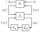
Refer to caption
Figure 4: Agent-level implementation of the 2\mathcal{H}_{2}-optimal controller with processing delays. This is the result of setting 𝒬^=0\hat{\mathcal{Q}}=0 in Fig. 3. The blocks that depend on the processing delay τ\tau are colored in green. All symbols are defined in Theorem 13.
Theorem 13.

Consider the setting of Theorem 8 with τ0\tau\geq 0. The agent-level implementation of all structured stabilizing controllers, parameterized by 𝒬^𝒮0\hat{\mathcal{Q}}\in\mathcal{H}_{\infty}\cap\mathcal{S}_{0}, is shown in Fig. 3. Here, the optimal controller is achieved when 𝒬^=0\hat{\mathcal{Q}}=0. In this case, we obtain the simpler structure of Fig. 4. All symbols used are defined in Theorems 8 and 12.

Proof.

See Section E.

4.1 Interpretation of optimal controller

Fig. 3 shows that Agent ii transmits the same signal viv_{i} to each of its strict descendants. When an agent receives the signals vi¯¯v_{\bar{\bar{i}}} from its strict ancestors i¯¯\bar{\bar{i}}, it selectively extracts and sums together certain components of the signals. To implement the optimal controller, each agent only needs to know the dynamics and topology of its descendants.

If the network has the additional property that there is at most one directed path connecting any two nodes333Also known as a multitree or a diamond-free poset., then the communication scheme can be further simplified. Since Agent ii’s decision uiu_{i} is a sum of terms from all ancestors, but each ancestor has exactly one path that leads to ii, the optimal controller can be implemented by transmitting all information to immediate descendants only and performing recursive summations. This scheme is illustrated for a four-node chain graph in Fig. 5.

Refer to caption
Figure 5: Four-agent chain graph with standard broadcast (top) and efficient immediate-neighbor implementation (bottom), which is possible because this graph is a multitree.
Remark 14.

The agent-level controller from Fig. 4 can be represented as the combination of an observer with transfer matrix 𝒯ii¯:=(sIAii¯Eni¯𝖳EniLiC2ii¯)1\mathcal{T}_{\underline{ii}}\mathrel{\mathchoice{\vbox{\hbox{$\displaystyle:$}}}{\vbox{\hbox{$\textstyle:$}}}{\vbox{\hbox{$\scriptstyle:$}}}{\vbox{\hbox{$\scriptscriptstyle:$}}}{=}}(sI-A_{\underline{ii}}-E_{n_{\underline{i}}}^{\mathsf{T}}E_{n_{i}}L^{i}C_{2_{i\underline{i}}})^{-1}, and a regulator with an LQR gain F~i\tilde{F}^{i} in Fig. 6. This yields a separation structure reminiscent of standard LQG theory [37].

Refer to caption
Figure 6: Agent-level implementation of the 2\mathcal{H}_{2}-optimal controller with processing delays, featuring an observer (red) and regulator (blue) separation structure. Here 𝒯ii¯:=(sIAii¯Eni¯𝖳EniLiC2ii¯)1\mathcal{T}_{\underline{ii}}\mathrel{\mathchoice{\vbox{\hbox{$\displaystyle:$}}}{\vbox{\hbox{$\textstyle:$}}}{\vbox{\hbox{$\scriptstyle:$}}}{\vbox{\hbox{$\scriptscriptstyle:$}}}{=}}(sI-A_{\underline{ii}}-E_{n_{\underline{i}}}^{\mathsf{T}}E_{n_{i}}L^{i}C_{2_{i\underline{i}}})^{-1} is the transfer matrix of the observer dynamics.
Remark 15.

Compared to the architecture proposed in [7, Fig. 4], the agent-level optimal controller in Fig. 4 is more efficient because each agent transmits a single vector viv_{i} to its descendants, instead of two.

Remark 16.

The controller in Fig. 4 has the form of a feed-forward Smith predictor, similar to Fig. 2 (bottom left). The FIR block Πui\Pi_{u_{i}} compensates for the effect of adobe delay. Similarly, the FIR block Πbi\Pi_{b_{i}} resembles the internal feedback in traditional dead-time controllers.

5 Characterizing the cost

In this section, we characterize the cost of any structured stabilizing controller. The cost is defined as J:=l(𝒫,𝒦)22=𝒯11+𝒯12𝒬𝒯2122J\mathrel{\mathchoice{\vbox{\hbox{$\displaystyle:$}}}{\vbox{\hbox{$\textstyle:$}}}{\vbox{\hbox{$\scriptstyle:$}}}{\vbox{\hbox{$\scriptscriptstyle:$}}}{=}}\bigl{\lVert}{\mathcal{F}_{l}(\mathcal{P},\mathcal{K})}\bigr{\rVert}_{2}^{2}=\bigl{\lVert}{\mathcal{T}_{11}+\mathcal{T}_{12}\mathcal{Q}\mathcal{T}_{21}}\bigr{\rVert}_{2}^{2}, where 𝒦\mathcal{K} is feasible for (8) or equivalently, 𝒬=u(𝒥1,𝒦)\mathcal{Q}=\mathcal{F}_{u}(\mathcal{J}^{-1},\mathcal{K}) is feasible for (23) (see Lemma 3). We show how to interpret the cost in different ways, and how to compute it efficiently. We illustrate our result using an example with N=4N=4 agents.

Refer to caption
Figure 7: Hierarchy of optimal costs for different communication patterns in a three-agent example. Additional cost is incurred if links are removed (blue dotted arrows), or if processing delay is added (green dottted arrows). Delayed edges are red. In this example, JcenJdecJdec,delJ_{\textup{cen}}\leq J_{\textup{dec}}\leq J_{\textup{dec},\textup{del}} and JcenJdelJdec,delJ_{\textup{cen}}\leq J_{\textup{del}}\leq J_{\textup{dec},\textup{del}} but JdecJ_{\textup{dec}} and JdelJ_{\textup{del}} are not comparable.
Refer to caption
Figure 8: Open-loop zero-input response of a network of four lightly damped oscillators.
Refer to caption
Figure 9: Closed-loop response of the four-oscillator system from Fig. 8 using the optimal controller from Theorem 8 for a diamond-shaped communication graph with no processing delay. The oscillators leverage the communication network to achieve synchronization.
Refer to caption
Figure 10: The average optimal cost, as a function of processing delay, for the 4-agent system of Fig. 9 with different network topologies. For each topology, the cost is an increasing function of the processing delay.
Theorem 17.

Consider the setting of Theorem 8. The optimal (minimal) costs for the cases: a fully connected graph with no delays, a decentralized graph with no delays, a fully connected graph with delays, and a decentralized graph with delays are:

Jcen\displaystyle J_{\textup{cen}} =tr(YcenC1𝖳C1)+tr(XcenLD21D21𝖳L𝖳),\displaystyle=\operatorname{\mathrm{tr}}(Y_{\textup{cen}}C_{1}^{\mathsf{T}}C_{1})+\operatorname{\mathrm{tr}}(X_{\textup{cen}}LD_{21}D_{21}^{\mathsf{T}}L^{\mathsf{T}}), (37a)
Jdec\displaystyle J_{\textup{dec}} =tr(YcenC1𝖳C1)+tr(XdecLD21D21𝖳L𝖳),\displaystyle=\operatorname{\mathrm{tr}}(Y_{\textup{cen}}C_{1}^{\mathsf{T}}C_{1})+\operatorname{\mathrm{tr}}(X_{\textup{dec}}LD_{21}D_{21}^{\mathsf{T}}L^{\mathsf{T}}), (37b)
Jdel\displaystyle J_{\textup{del}} =tr(YcenC1𝖳C1)+tr(XdelLD21D21𝖳L𝖳),\displaystyle=\operatorname{\mathrm{tr}}(Y_{\textup{cen}}C_{1}^{\mathsf{T}}C_{1})+\operatorname{\mathrm{tr}}(X_{\textup{del}}LD_{21}D_{21}^{\mathsf{T}}L^{\mathsf{T}}), (37c)
Jdec,del\displaystyle J_{\textup{dec},\textup{del}} =tr(YcenC1𝖳C1)+tr(Xdec,delLD21D21𝖳L𝖳),\displaystyle=\operatorname{\mathrm{tr}}(Y_{\textup{cen}}C_{1}^{\mathsf{T}}C_{1})+\operatorname{\mathrm{tr}}(X_{\textup{dec,del}}LD_{21}D_{21}^{\mathsf{T}}L^{\mathsf{T}}), (37d)

respectively. If a feasible but sub-optimal 𝒬\mathcal{Q} is used in any of the above cases, write 𝒬Δ:=𝒬𝒬opt\mathcal{Q}_{\Delta}\mathrel{\mathchoice{\vbox{\hbox{$\displaystyle:$}}}{\vbox{\hbox{$\textstyle:$}}}{\vbox{\hbox{$\scriptstyle:$}}}{\vbox{\hbox{$\scriptscriptstyle:$}}}{=}}\mathcal{Q}-\mathcal{Q}_{\textup{opt}}. The cost of this sub-optimal 𝒬\mathcal{Q} is found by adding JQ:=𝒯12𝒬ΔD2122J_{Q}\mathrel{\mathchoice{\vbox{\hbox{$\displaystyle:$}}}{\vbox{\hbox{$\textstyle:$}}}{\vbox{\hbox{$\scriptstyle:$}}}{\vbox{\hbox{$\scriptscriptstyle:$}}}{=}}\bigl{\lVert}{\mathcal{T}_{12}\mathcal{Q}_{\Delta}D_{21}}\bigr{\rVert}_{2}^{2} to (37a)–(37d). The various symbols are defined as

Xdec:=blkd({Xi(1,1)}),Xdel:=blkd({Ξcτi(1,1)}),\displaystyle X_{\textup{dec}}\mathrel{\mathchoice{\vbox{\hbox{$\displaystyle:$}}}{\vbox{\hbox{$\textstyle:$}}}{\vbox{\hbox{$\scriptstyle:$}}}{\vbox{\hbox{$\scriptscriptstyle:$}}}{=}}\operatorname{\mathrm{blkd}}(\{X^{i}(1,1)\}),\quad X_{\textup{del}}\mathrel{\mathchoice{\vbox{\hbox{$\displaystyle:$}}}{\vbox{\hbox{$\textstyle:$}}}{\vbox{\hbox{$\scriptstyle:$}}}{\vbox{\hbox{$\scriptscriptstyle:$}}}{=}}\operatorname{\mathrm{blkd}}(\{\Xi_{c_{\tau}}^{i}(1,1)\}),
Xdec,del:=blkd({Ξτi(1,1)}),and satisfy\displaystyle X_{\textup{dec,del}}\mathrel{\mathchoice{\vbox{\hbox{$\displaystyle:$}}}{\vbox{\hbox{$\textstyle:$}}}{\vbox{\hbox{$\scriptstyle:$}}}{\vbox{\hbox{$\scriptscriptstyle:$}}}{=}}\operatorname{\mathrm{blkd}}(\{\Xi_{\tau}^{i}(1,1)\}),\qquad\textit{and satisfy}
blkd({Xcen(i,i)})\displaystyle\operatorname{\mathrm{blkd}}(\{X_{\textup{cen}}(i,i)\}) XdecXdec,del,\displaystyle\preceq X_{\textup{dec}}\preceq X_{\textup{dec,del}}, (38a)
blkd({Xcen(i,i)})\displaystyle\operatorname{\mathrm{blkd}}(\{X_{\textup{cen}}(i,i)\}) XdelXdec,del.\displaystyle\preceq X_{\textup{del}}\preceq X_{\textup{dec,del}}. (38b)

Xcen,Ycen,FcenX_{\textup{cen}},Y_{\textup{cen}},F_{\textup{cen}}, and LL are defined in Section 2.2.1. Ξτi\Xi_{\tau}^{i} and Ξcτi\Xi_{c_{\tau}}^{i} are defined in Sections F.6 and F.7, respectively.

Proof.

See Section F.

In (37a) we recognize JcenJ_{\textup{cen}} as the standard LQG cost (fully connected graph with no delays). Further, there are two intuitive interpretations for Theorem 17 that are represented in Fig. 7 for a 3-agents system. The intermediate graph topologies are different, but the starting and ending topologies are equal for both. Along the upper path, JdecJcenJ_{\textup{dec}}-J_{\textup{cen}} is the additional cost incurred due to decentralization alone, and Jdec,delJdecJ_{\textup{dec},\textup{del}}-J_{\textup{dec}} is the further additional cost due to delays. Likewise, along the lower path, JdelJcenJ_{\textup{del}}-J_{\textup{cen}} is the additional cost due to delays alone and Jdec,delJdelJ_{\textup{dec},\textup{del}}-J_{\textup{del}} is the further additional cost due to decentralization. Finally, JQJ_{Q} is the additional cost incurred due to suboptimality. Theorem 17 unifies existing cost decomposition results for the centralized [37, §14.6], decentralized [18, Thm. 16], and delayed [23, Prop. 6] cases.

Remark 18.

Delay and decentralization do not contribute independently to the cost. Specifically, the marginal increase in cost due to adding processing delays depends on the graph topology. Likewise, the marginal increase in cost due to removing communication links depends on the processing delay. In other words, Jcen+Jdec,delJdec+JdelJ_{\textup{cen}}+J_{\textup{dec},\textup{del}}\neq J_{\textup{dec}}+J_{\textup{del}}.

Remark 19.

There is a dual expression for the cost JcenJ_{\textup{cen}} in (37a):

Jcen=tr(XcenB1B1𝖳)+tr(YcenFcen𝖳D12𝖳D12Fcen).J_{\textup{cen}}=\operatorname{\mathrm{tr}}(X_{\textup{cen}}B_{1}B_{1}^{\mathsf{T}})+\operatorname{\mathrm{tr}}(Y_{\textup{cen}}F_{\textup{cen}}^{\mathsf{T}}D_{12}^{\mathsf{T}}D_{12}F_{\textup{cen}}).

The corresponding dual expressions for (37b)–(37d) are unfortunately more complicated. See Section F.3 for details.

5.1 Synchronization example

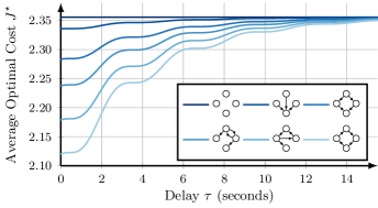
We demonstrate Theorem 8 via a simple structured LQG example. We consider N=4N=4 identical lightly damped oscillators. The oscillators begin with different initial conditions and the goal is to achieve synchronization. The oscillators have identical dynamics defined by the differential equations in Figs. 8 and 9. Fig. 8 shows the open-loop zero-input response for the four oscillators with given initial conditions. Due to the light damping, the states slowly converge to zero as tt\rightarrow\infty.

Fig. 9 shows the closed-loop response using the optimal controller from Theorem 8 for a diamond-shaped communication network with no processing delay. The controller states are initialized to match the initial state of the plant. Since the observer is an unbiased estimator, the LQG controller replicates the behavior of full-state feedback LQR. Fig. 9 shows the four oscillators leveraging their shared information to achieve synchronization to a common oscillation pattern.

In Fig. 10, we use the same system as in Fig. 9, but we plot the total average cost as a function of time delay for various network topologies. The highest cost corresponds to a fully disconnected network, while the lowest cost corresponds to a fully connected network. In the limit as τ\tau\to\infty (infinite processing delay), the cost tends to that of the fully disconnected case.

6 Conclusion

We studied a structured optimal control problem where multiple dynamically decoupled agents communicate over a delay network. Specifically, we characterized the structure and efficient implementation of optimal controllers at the individual agent level. We now propose some possible future applications for our work.

First, our approach can be readily generalized to treat cases with a combination of processing delays and network latency, where the various delays are heterogeneous but known [5]. Next, the observer-regulator architecture elucidated in Fig. 6 could also be used to develop heuristics for solving cooperative control problems where the agents’ dynamics are nonlinear or the noise distributions are non-Gaussian. Examples could include decentralized versions of the Extended Kalman Filter or Unscented Kalman Filter. Finally, our closed-form expressions for the optimal cost can serve as lower bounds to the cost of practical implementation that have additional memory, power, or bandwidth limitations.

Appendices

A Definition of the Γ\Gamma function

The Γ\Gamma function takes in a four-block plant 𝒫\mathcal{P} and adobe delay matrix Λmi\Lambda_{m}^{i} and returns a transformed plant 𝒫~\tilde{\mathcal{P}} and FIR systems Πu\Pi_{u}, Πb\Pi_{b}. As in [23], we first consider the special case where D12𝖳D12=ID_{12}^{\mathsf{T}}D_{12}=I. The completion operator πτ{}\pi_{\tau}\{\cdot\} acts on a rational LTI system delayed by τ\tau and returns the unique FIR system supported on [0,τ][0,\tau] that provides a rational completion:

πτ{[ABC0]esτ}:=[AeAτBC0][ABC0]esτ.\pi_{\tau}\Biggl{\{}\left[\begin{array}[]{c|c}A&B\\ \hline\cr\rule{0.0pt}{9.90276pt}C&0\end{array}\right]\!e^{-s\tau}\Biggr{\}}\mathrel{\mathchoice{\vbox{\hbox{$\displaystyle:$}}}{\vbox{\hbox{$\textstyle:$}}}{\vbox{\hbox{$\scriptstyle:$}}}{\vbox{\hbox{$\scriptscriptstyle:$}}}{=}}\left[\begin{array}[]{c|c}A&e^{-A\tau}\!B\\ \hline\cr\rule{0.0pt}{9.90276pt}C&0\end{array}\right]-\left[\begin{array}[]{c|c}A&B\\ \hline\cr\rule{0.0pt}{9.90276pt}C&0\end{array}\right]e^{-s\tau}\!.

The input matrices B2B_{2} and D12D_{12} of 𝒫\mathcal{P} are partitioned according to the blocks of adobe delay matrix Λmi\Lambda_{m}^{i}. So, B2=[B20B2τ]{B}_{2}=\begin{bmatrix}B_{2_{0}}&B_{2_{\tau}}\end{bmatrix}, where the two blocks correspond to inputs with delay 0 and τ\tau, respectively. D12D_{12} is partitioned in a similar manner. Define the Hamiltonian matrix

H=[H11H12H21H22]:=[AB20D120𝖳C1B20B20𝖳C1𝖳PτC1A𝖳+C1𝖳D120B20𝖳],H=\begin{bmatrix}H_{11}&H_{12}\\ H_{21}&H_{22}\end{bmatrix}\mathrel{\mathchoice{\vbox{\hbox{$\displaystyle:$}}}{\vbox{\hbox{$\textstyle:$}}}{\vbox{\hbox{$\scriptstyle:$}}}{\vbox{\hbox{$\scriptscriptstyle:$}}}{=}}\begin{bmatrix}A\!-\!B_{2_{0}}D_{12_{0}}^{\mathsf{T}}C_{1}&-B_{2_{0}}B_{2_{0}}^{\mathsf{T}}\\ -C_{1}^{\mathsf{T}}P_{\tau}C_{1}&-A^{\mathsf{T}}\!+\!C_{1}^{\mathsf{T}}D_{12_{0}}B_{2_{0}}^{\mathsf{T}}\end{bmatrix}\!,

where P0:=D120D120𝖳P_{0}\mathrel{\mathchoice{\vbox{\hbox{$\displaystyle:$}}}{\vbox{\hbox{$\textstyle:$}}}{\vbox{\hbox{$\scriptstyle:$}}}{\vbox{\hbox{$\scriptscriptstyle:$}}}{=}}D_{{12}_{0}}D_{{12}_{0}}^{\mathsf{T}} and Pτ:=IP0P_{\tau}\mathrel{\mathchoice{\vbox{\hbox{$\displaystyle:$}}}{\vbox{\hbox{$\textstyle:$}}}{\vbox{\hbox{$\scriptstyle:$}}}{\vbox{\hbox{$\scriptscriptstyle:$}}}{=}}I-P_{0}, and define its matrix exponential as Σ:=eHτ\Sigma\mathrel{\mathchoice{\vbox{\hbox{$\displaystyle:$}}}{\vbox{\hbox{$\textstyle:$}}}{\vbox{\hbox{$\scriptstyle:$}}}{\vbox{\hbox{$\scriptscriptstyle:$}}}{=}}e^{H\tau}. Define the modified matrices

B~2\displaystyle\tilde{B}_{2} :=[B20Σ12𝖳C1𝖳D12τ+Σ22𝖳B2τ]\displaystyle\mathrel{\mathchoice{\vbox{\hbox{$\displaystyle:$}}}{\vbox{\hbox{$\textstyle:$}}}{\vbox{\hbox{$\scriptstyle:$}}}{\vbox{\hbox{$\scriptscriptstyle:$}}}{=}}\begin{bmatrix}B_{2_{0}}&\Sigma_{12}^{\mathsf{T}}C_{1}^{\mathsf{T}}D_{{12}_{\tau}}+\Sigma_{22}^{\mathsf{T}}B_{2_{\tau}}\end{bmatrix}
C~1\displaystyle\tilde{C}_{1} :=(PτC1+P0C1Σ22𝖳D120B20𝖳Σ21𝖳)Σ22𝖳,\displaystyle\mathrel{\mathchoice{\vbox{\hbox{$\displaystyle:$}}}{\vbox{\hbox{$\textstyle:$}}}{\vbox{\hbox{$\scriptstyle:$}}}{\vbox{\hbox{$\scriptscriptstyle:$}}}{=}}\left(P_{\tau}C_{1}+P_{0}C_{1}\Sigma_{22}^{\mathsf{T}}-D_{{12}_{0}}B_{2_{0}}^{\mathsf{T}}\Sigma_{21}^{\mathsf{T}}\right)\Sigma_{22}^{-\mathsf{T}},

where the Σij\Sigma_{ij} are partitioned the same way as the HijH_{ij}. The modified four-block plant output by Γ\Gamma is then

𝒫~:=[𝒫~11𝒫~12𝒫21𝒫~22]:=[AB1B~2C~10D12C2D210],\tilde{\mathcal{P}}\mathrel{\mathchoice{\vbox{\hbox{$\displaystyle:$}}}{\vbox{\hbox{$\textstyle:$}}}{\vbox{\hbox{$\scriptstyle:$}}}{\vbox{\hbox{$\scriptscriptstyle:$}}}{=}}\begin{bmatrix}\tilde{\mathcal{P}}_{11}&\tilde{\mathcal{P}}_{12}\\ \mathcal{P}_{21}&\tilde{\mathcal{P}}_{22}\end{bmatrix}\mathrel{\mathchoice{\vbox{\hbox{$\displaystyle:$}}}{\vbox{\hbox{$\textstyle:$}}}{\vbox{\hbox{$\scriptstyle:$}}}{\vbox{\hbox{$\scriptscriptstyle:$}}}{=}}\left[\begin{array}[]{c|cc}A&B_{1}&\tilde{B}_{2}\\ \hline\cr\rule{0.0pt}{9.90276pt}\tilde{C}_{1}&0&D_{12}\\ C_{2}&D_{21}&0\end{array}\right],

Finally, define the FIR systems

[Π~uΠ~b]:=πτ{[H11H12B2τH21H22C1𝖳D12τD120𝖳C1B200C200]esτ}.\begin{bmatrix}\tilde{\Pi}_{u}\\ \tilde{\Pi}_{b}\end{bmatrix}\mathrel{\mathchoice{\vbox{\hbox{$\displaystyle:$}}}{\vbox{\hbox{$\textstyle:$}}}{\vbox{\hbox{$\scriptstyle:$}}}{\vbox{\hbox{$\scriptscriptstyle:$}}}{=}}\pi_{\tau}\!\left\{\left[\begin{array}[]{cc|c}H_{11}&H_{12}&B_{2_{\tau}}\\ H_{21}&H_{22}&-C_{1}^{\mathsf{T}}D_{12_{\tau}}\\ \hline\cr\rule{0.0pt}{9.90276pt}D_{12_{0}}^{\mathsf{T}}{C}_{1}&B_{2_{0}}&0\\ C_{2}&0&0\end{array}\right]e^{-s\tau}\right\}.

FIR outputs of Γ\Gamma are Πu:=[IΠ~u0I]\Pi_{u}\mathrel{\mathchoice{\vbox{\hbox{$\displaystyle:$}}}{\vbox{\hbox{$\textstyle:$}}}{\vbox{\hbox{$\scriptstyle:$}}}{\vbox{\hbox{$\scriptscriptstyle:$}}}{=}}\begin{bmatrix}I&\tilde{\Pi}_{u}\\ 0&I\end{bmatrix} and Πb:=[0Π~b]\Pi_{b}\mathrel{\mathchoice{\vbox{\hbox{$\displaystyle:$}}}{\vbox{\hbox{$\textstyle:$}}}{\vbox{\hbox{$\scriptstyle:$}}}{\vbox{\hbox{$\scriptscriptstyle:$}}}{=}}\begin{bmatrix}0&\tilde{\Pi}_{b}\end{bmatrix}.

In the general case D12𝖳D12ID_{12}^{\mathsf{T}}D_{12}\neq I, we can use a standard change of variables to transform back to the case D12𝖳D12=ID_{12}^{\mathsf{T}}D_{12}=I. See [21, Rem. 2] for details.

B Gramian equations

Here we provide the set of Lyapunov equations that are uniquely associated with the multi-agent problem.

Lemma 20.

Suppose (Xcen,Fcen)(X_{\textup{cen}},F_{\textup{cen}}) and (Xi,Fi)(X^{i},F^{i}) are defined in (9a) and (16a) respectively. Then WXi:=XiXcenii¯0W_{X}^{i}\mathrel{\mathchoice{\vbox{\hbox{$\displaystyle:$}}}{\vbox{\hbox{$\textstyle:$}}}{\vbox{\hbox{$\scriptstyle:$}}}{\vbox{\hbox{$\scriptscriptstyle:$}}}{=}}X^{i}-X_{\textup{cen}_{\underline{ii}}}\succeq 0 is the unique solution to the Lyapunov equation

(Aii¯+B2ii¯Fi)𝖳WXi+WXi(Aii¯+B2ii¯Fi)+(Emi¯FiFcenEni¯)𝖳D12𝖳D12(Emi¯FiFcenEni¯)=0.(A_{\underline{ii}}+B_{2_{\underline{ii}}}F^{i})^{\mathsf{T}}W_{X}^{i}+W_{X}^{i}(A_{\underline{ii}}+B_{2_{\underline{ii}}}F^{i})+(E_{m_{\underline{i}}}F^{i}-F_{\textup{cen}}E_{n_{\underline{i}}})^{\mathsf{T}}D_{12}^{\mathsf{T}}D_{12}(E_{m_{\underline{i}}}F^{i}-F_{\textup{cen}}E_{n_{\underline{i}}})=0. (39)

Proof.

Left and right multiply the ARE for (9a) by Eni¯𝖳E_{n_{\underline{i}}}^{\mathsf{T}} and Eni¯E_{n_{\underline{i}}} respectively, and subtract it from (16a). The result follows from algebraic manipulation and applying the definitions of FiF^{i} and FcenF_{\textup{cen}}. Since the final term in (39) is positive semidefinite and Aii¯+B2ii¯FiA_{\underline{ii}}+B_{2_{\underline{ii}}}F^{i} is Hurwitz, it follows that WXi:=XiXcenii¯0W_{X}^{i}\mathrel{\mathchoice{\vbox{\hbox{$\displaystyle:$}}}{\vbox{\hbox{$\textstyle:$}}}{\vbox{\hbox{$\scriptstyle:$}}}{\vbox{\hbox{$\scriptscriptstyle:$}}}{=}}X^{i}-X_{\textup{cen}_{\underline{ii}}}\succeq 0 and is unique.

We also have a dual analog to Lemma 20, provided below.

Lemma 21.

Consider the setting of Lemma 20. There exists a unique WYi0W_{Y}^{i}\succeq 0 that satisfies the Lyapunov equation

(Aii¯+B2ii¯Fi)WYi+WYi(Aii¯+B2ii¯Fi)𝖳+Eni¯𝖳L¯𝟏¯pD21D21𝖳𝟏¯p𝖳L¯𝖳Eni¯=0.(A_{\underline{ii}}+B_{2_{\underline{ii}}}F^{i})W_{Y}^{i}+W_{Y}^{i}(A_{\underline{ii}}+B_{2_{\underline{ii}}}F^{i})^{\mathsf{T}}+E_{n_{\underline{i}}}^{\mathsf{T}}\bar{L}\bar{\mathbf{1}}_{p}D_{21}D_{21}^{\mathsf{T}}\bar{\mathbf{1}}_{p}^{\mathsf{T}}\bar{L}^{\mathsf{T}}E_{n_{\underline{i}}}=0. (40)

Proof.

Since Eni¯𝖳L¯𝟏¯pD21D21𝖳𝟏¯p𝖳L¯𝖳Eni¯0E_{n_{\underline{i}}}^{\mathsf{T}}\bar{L}\bar{\mathbf{1}}_{p}D_{21}D_{21}^{\mathsf{T}}\bar{\mathbf{1}}_{p}^{\mathsf{T}}\bar{L}^{\mathsf{T}}E_{n_{\underline{i}}}\succeq 0 and the matrix Aii¯+B2ii¯FiA_{\underline{ii}}+B_{2_{\underline{ii}}}F^{i} is Hurwitz, WYi0W_{Y}^{i}\succeq 0 and is unique.

C Proof of Theorem 8

For the case τ=0\tau=0, we can replace 𝒬𝒮τ\mathcal{Q}\in\mathcal{H}_{\infty}\cap\mathcal{S}_{\tau} by 𝒬2𝒮0\mathcal{Q}\in\mathcal{H}_{2}\cap\mathcal{H}_{\infty}\cap\mathcal{S}_{0} in (23) because the closed-loop map must be strictly proper in order to have a finite 2\mathcal{H}_{2} norm. Since 𝒯11\mathcal{T}_{11} is strictly proper, this forces 𝒬\mathcal{Q} to be strictly proper as well, and hence 𝒬2\mathcal{Q}\in\mathcal{H}_{2}\cap\mathcal{H}_{\infty}. Further, if 𝒬\mathcal{Q} is rational, we have 𝒬2\mathcal{Q}\in\mathcal{RH}_{2}. The optimization problem (23) is a least squares problem with a subspace constraint, so the necessary and sufficient conditions for optimality are given by the normal equations 𝒯12(𝒯11+𝒯12𝒬𝒯21)𝒯21(2𝒮0)\mathcal{T}_{12}^{\sim}(\mathcal{T}_{11}+\mathcal{T}_{12}\mathcal{Q}\mathcal{T}_{21})\mathcal{T}_{21}^{\sim}\in\left(\mathcal{RH}_{2}\cap\mathcal{S}_{0}\right)^{\perp} with the constraint that 𝒬2𝒮0\mathcal{Q}\in\mathcal{RH}_{2}\cap\mathcal{S}_{0}.

We can check membership (2𝒮0)\mathcal{F}\in(\mathcal{RH}_{2}\cap\mathcal{S}_{0})^{\perp} by checking if ij2\mathcal{F}_{ij}\in\mathcal{RH}_{2}^{\perp} whenever there is a path jij\to i. For example, consider the two-node graph 121\to 2. Then we have

2𝒮0=[2022]and(2𝒮0)=[2222].\mathcal{RH}_{2}\cap\mathcal{S}_{0}=\begin{bmatrix}\mathcal{RH}_{2}&0\\ \mathcal{RH}_{2}&\mathcal{RH}_{2}\end{bmatrix}\quad\text{and}\quad(\mathcal{RH}_{2}\cap\mathcal{S}_{0})^{\perp}=\begin{bmatrix}\mathcal{RH}_{2}^{\perp}&\mathcal{L}_{2}\\ \mathcal{RH}_{2}^{\perp}&\mathcal{RH}_{2}^{\perp}\end{bmatrix}.

So here, (2𝒮0)\mathcal{F}\in(\mathcal{RH}_{2}\cap\mathcal{S}_{0})^{\perp} if and only if 11,21,222\mathcal{F}_{11},\mathcal{F}_{21},\mathcal{F}_{22}\in\mathcal{RH}_{2}^{\perp}. We will show that the proposed 𝒬opt\mathcal{Q}_{\textup{opt}} in (31) is optimal by directly verifying the normal equations.

Substituting 𝒬opt\mathcal{Q}_{\textup{opt}} from (31) into 𝒯11+𝒯12𝒬opt𝒯21\mathcal{T}_{11}+\mathcal{T}_{12}\mathcal{Q}_{\textup{opt}}\mathcal{T}_{21} with 𝒯ij\mathcal{T}_{ij} defined in (28), we obtain the closed-loop map

𝒯11+𝒯12𝒬opt𝒯21=[AclBclCcl0]:=[A¯+B¯F¯L¯C¯𝟏¯nL¯𝟏¯pD210ALBLC1𝟏¯n𝖳+D12𝟏¯m𝖳F¯C10],\mathcal{T}_{11}+\mathcal{T}_{12}\mathcal{Q}_{\textup{opt}}\mathcal{T}_{21}=\left[\begin{array}[]{c|c}A_{\textup{cl}}&B_{\textup{cl}}\\ \hline\cr\rule{0.0pt}{9.90276pt}C_{\textup{cl}}&0\end{array}\right]\mathrel{\mathchoice{\vbox{\hbox{$\displaystyle:$}}}{\vbox{\hbox{$\textstyle:$}}}{\vbox{\hbox{$\scriptstyle:$}}}{\vbox{\hbox{$\scriptscriptstyle:$}}}{=}}\left[\begin{array}[]{cc|c}\bar{A}+\bar{B}\bar{F}&-\bar{L}\bar{C}\bar{\mathbf{1}}_{n}&-\bar{L}\bar{\mathbf{1}}_{p}D_{21}\\ 0&A_{L}&B_{L}\\ \hline\cr\rule{0.0pt}{9.90276pt}C_{1}\bar{\mathbf{1}}_{n}^{\mathsf{T}}+D_{12}\bar{\mathbf{1}}_{m}^{\mathsf{T}}\bar{F}&C_{1}&0\end{array}\right], (41)

where AL:=A+LC2A_{L}\mathrel{\mathchoice{\vbox{\hbox{$\displaystyle:$}}}{\vbox{\hbox{$\textstyle:$}}}{\vbox{\hbox{$\scriptstyle:$}}}{\vbox{\hbox{$\scriptscriptstyle:$}}}{=}}A+LC_{2} and BL:=B1+LD21B_{L}\mathrel{\mathchoice{\vbox{\hbox{$\displaystyle:$}}}{\vbox{\hbox{$\textstyle:$}}}{\vbox{\hbox{$\scriptstyle:$}}}{\vbox{\hbox{$\scriptscriptstyle:$}}}{=}}B_{1}+LD_{21}. Next, we show that the controllability Gramian for the closed loop map is block-diagonal.

Lemma 22.

The controllability Gramian for the closed-loop map (41) is given by

Θ:=blkd({Eni¯WYiEni¯𝖳}i[N],Ycen),\Theta\mathrel{\mathchoice{\vbox{\hbox{$\displaystyle:$}}}{\vbox{\hbox{$\textstyle:$}}}{\vbox{\hbox{$\scriptstyle:$}}}{\vbox{\hbox{$\scriptscriptstyle:$}}}{=}}\operatorname{\mathrm{blkd}}(\{E_{n_{\underline{i}}}W_{Y}^{i}E_{n_{\underline{i}}}^{\mathsf{T}}\}_{i\in[N]},Y_{\textup{cen}}),

where YcenY_{\textup{cen}} and WYiW_{Y}^{i} are defined in Eqs. 9b and 21, respectively. In other words, Θ0\Theta\succeq 0 is the unique solution to AclΘ+ΘAcl𝖳+BclBcl𝖳=0A_{\textup{cl}}\Theta+\Theta A_{\textup{cl}}^{\mathsf{T}}+B_{\textup{cl}}B_{\textup{cl}}^{\mathsf{T}}=0.

Proof.

AclA_{\textup{cl}} is Hurwitz and BclBcl𝖳0B_{\textup{cl}}B_{\textup{cl}}^{\mathsf{T}}\succeq 0 so the Lyapunov equation has a unique solution and Θ0\Theta\succeq 0. We can verify the solution by direct substitution using Lemma 21 and the ARE associated with (9b).

Lemma 22 has the following statistical interpretation. If the controlled system (41) is driven by standard Gaussian noise, its state in these coordinates will have a steady-state covariance Θ\Theta, so each block component will be mutually independent.

C.1 Proof of optimality

Let Ω:=𝒯12(𝒯11+𝒯12𝒬opt𝒯21)𝒯21\Omega\mathrel{\mathchoice{\vbox{\hbox{$\displaystyle:$}}}{\vbox{\hbox{$\textstyle:$}}}{\vbox{\hbox{$\scriptstyle:$}}}{\vbox{\hbox{$\scriptscriptstyle:$}}}{=}}\mathcal{T}_{12}^{\sim}(\mathcal{T}_{11}+\mathcal{T}_{12}\mathcal{Q}_{\textup{opt}}\mathcal{T}_{21})\mathcal{T}_{21}^{\sim}. Substituting 𝒬opt\mathcal{Q}_{\textup{opt}} from (31) and using (41), we obtain

Ω\displaystyle\Omega =[AK𝖳CK𝖳Ccl000AclBclBL𝖳BclD21𝖳00AL𝖳C2𝖳B2𝖳D12𝖳Ccl00],\displaystyle={\left[\begin{array}[]{ccc|c}-A_{K}^{\mathsf{T}}&-C_{K}^{\mathsf{T}}C_{\textup{cl}}&0&0\\ 0&A_{\textup{cl}}&B_{\textup{cl}}B_{L}^{\mathsf{T}}&B_{\textup{cl}}D_{21}^{\mathsf{T}}\\ 0&0&-A_{L}^{\mathsf{T}}&-C_{2}^{\mathsf{T}}\\ \hline\cr\rule{0.0pt}{9.90276pt}B_{2}^{\mathsf{T}}&D_{12}^{\mathsf{T}}C_{\textup{cl}}&0&0\end{array}\right]}, (46)

where AK:=A+B2FdA_{K}\mathrel{\mathchoice{\vbox{\hbox{$\displaystyle:$}}}{\vbox{\hbox{$\textstyle:$}}}{\vbox{\hbox{$\scriptstyle:$}}}{\vbox{\hbox{$\scriptscriptstyle:$}}}{=}}A+B_{2}F_{d}, CK:=C1+D12FdC_{K}\mathrel{\mathchoice{\vbox{\hbox{$\displaystyle:$}}}{\vbox{\hbox{$\textstyle:$}}}{\vbox{\hbox{$\scriptstyle:$}}}{\vbox{\hbox{$\scriptscriptstyle:$}}}{=}}C_{1}+D_{12}F_{d}, and AclA_{\textup{cl}}, BclB_{\textup{cl}}, CclC_{\textup{cl}}, are defined in (41). Apply the state transformation

T=[I[𝟏¯n𝖳X¯0]𝟏¯n𝖳X¯W¯𝟏¯p0IΘ𝟏¯p00I]\displaystyle T=\begin{bmatrix}I&\begin{bmatrix}\bar{\mathbf{1}}_{n}^{\mathsf{T}}\bar{X}&0\end{bmatrix}&\bar{\mathbf{1}}_{n}^{\mathsf{T}}\bar{X}\bar{W}\bar{\mathbf{1}}_{p}\\ 0&I&\Theta\bar{\mathbf{1}}_{p}\\ 0&0&I\end{bmatrix}

to (46), where we defined W¯:=blkd({Eni¯WYiEni¯𝖳}i[N])\bar{W}\mathrel{\mathchoice{\vbox{\hbox{$\displaystyle:$}}}{\vbox{\hbox{$\textstyle:$}}}{\vbox{\hbox{$\scriptstyle:$}}}{\vbox{\hbox{$\scriptscriptstyle:$}}}{=}}\operatorname{\mathrm{blkd}}(\{E_{n_{\underline{i}}}W_{Y}^{i}E_{n_{\underline{i}}}^{\mathsf{T}}\}_{i\in[N]}) and X¯:=blkd({Eni¯WXiEni¯𝖳+Xcen}i[N])\bar{X}\mathrel{\mathchoice{\vbox{\hbox{$\displaystyle:$}}}{\vbox{\hbox{$\textstyle:$}}}{\vbox{\hbox{$\scriptstyle:$}}}{\vbox{\hbox{$\scriptscriptstyle:$}}}{=}}\operatorname{\mathrm{blkd}}(\{E_{n_{\underline{i}}}W_{X}^{i}E_{n_{\underline{i}}}^{\mathsf{T}}+X_{\textup{cen}}\}_{i\in[N]}), and Θ\Theta is defined in Lemma 22. The transformed Ω\Omega is

Ω=[AK𝖳10A¯+B¯F¯L¯C¯𝟏¯n2300AL56000AL𝖳C2𝖳B2𝖳4D12𝖳C10],\displaystyle\Omega={\left[\begin{array}[]{cccc|c}-A_{K}^{\mathsf{T}}&{\star}_{1}&\star&\star&\star\\ 0&\bar{A}+\bar{B}\bar{F}&-\bar{L}\bar{C}\bar{\mathbf{1}}_{n}&{\star}_{2}&{\star}_{3}\\ 0&0&A_{L}&{\star}_{5}&{\star}_{6}\\ 0&0&0&-A_{L}^{\mathsf{T}}&-C_{2}^{\mathsf{T}}\\ \hline\cr\rule{0.0pt}{9.90276pt}B_{2}^{\mathsf{T}}&{\star}_{4}&D_{12}^{\mathsf{T}}C_{1}&\star&0\end{array}\right]},

where we have defined the symbols

1\displaystyle{\star}_{1} :=AK𝖳𝟏¯n𝖳X¯CK𝖳(C1𝟏¯n𝖳+D12𝟏¯m𝖳F¯)𝟏¯n𝖳X¯(A¯+B¯F¯)\displaystyle\mathrel{\mathchoice{\vbox{\hbox{$\displaystyle:$}}}{\vbox{\hbox{$\textstyle:$}}}{\vbox{\hbox{$\scriptstyle:$}}}{\vbox{\hbox{$\scriptscriptstyle:$}}}{=}}-A_{K}^{\mathsf{T}}\bar{\mathbf{1}}_{n}^{\mathsf{T}}\bar{X}\!-\!C_{K}^{\mathsf{T}}(C_{1}\bar{\mathbf{1}}_{n}^{\mathsf{T}}\!+\!D_{12}\bar{\mathbf{1}}_{m}^{\mathsf{T}}\bar{F})\!-\!\bar{\mathbf{1}}_{n}^{\mathsf{T}}\bar{X}(\bar{A}\!+\!\bar{B}\bar{F})
2\displaystyle{\star}_{2} :=L¯𝟏¯pD21BL𝖳L¯C¯𝟏¯nYcen+(A¯+B¯F¯)W¯𝟏¯p+W¯𝟏¯pAL𝖳\displaystyle\mathrel{\mathchoice{\vbox{\hbox{$\displaystyle:$}}}{\vbox{\hbox{$\textstyle:$}}}{\vbox{\hbox{$\scriptstyle:$}}}{\vbox{\hbox{$\scriptscriptstyle:$}}}{=}}-\bar{L}\bar{\mathbf{1}}_{p}D_{21}B_{L}^{\mathsf{T}}\!-\!\bar{L}\bar{C}\bar{\mathbf{1}}_{n}Y_{\textup{cen}}\!+\!(\bar{A}\!+\!\bar{B}\bar{F})\bar{W}\bar{\mathbf{1}}_{p}\!+\!\bar{W}\bar{\mathbf{1}}_{p}A_{L}^{\mathsf{T}}
3\displaystyle{\star}_{3} :=L¯𝟏¯pD21𝖳+W¯𝟏¯pC2𝖳\displaystyle\mathrel{\mathchoice{\vbox{\hbox{$\displaystyle:$}}}{\vbox{\hbox{$\textstyle:$}}}{\vbox{\hbox{$\scriptstyle:$}}}{\vbox{\hbox{$\scriptscriptstyle:$}}}{=}}-\bar{L}\bar{\mathbf{1}}_{p}D_{21}^{\mathsf{T}}+\bar{W}\bar{\mathbf{1}}_{p}C_{2}^{\mathsf{T}}
4\displaystyle{\star}_{4} :=D12𝖳(C1𝟏¯n𝖳+D12𝟏¯m𝖳F¯)+B2𝖳𝟏¯n𝖳X¯\displaystyle\mathrel{\mathchoice{\vbox{\hbox{$\displaystyle:$}}}{\vbox{\hbox{$\textstyle:$}}}{\vbox{\hbox{$\scriptstyle:$}}}{\vbox{\hbox{$\scriptscriptstyle:$}}}{=}}D_{12}^{\mathsf{T}}(C_{1}\bar{\mathbf{1}}_{n}^{\mathsf{T}}+D_{12}\bar{\mathbf{1}}_{m}^{\mathsf{T}}\bar{F})+B_{2}^{\mathsf{T}}\bar{\mathbf{1}}_{n}^{\mathsf{T}}\bar{X}
5\displaystyle{\star}_{5} :=ALYcen+BLBL𝖳+YcenAL𝖳\displaystyle\mathrel{\mathchoice{\vbox{\hbox{$\displaystyle:$}}}{\vbox{\hbox{$\textstyle:$}}}{\vbox{\hbox{$\scriptstyle:$}}}{\vbox{\hbox{$\scriptscriptstyle:$}}}{=}}A_{L}Y_{\textup{cen}}+B_{L}B_{L}^{\mathsf{T}}+Y_{\textup{cen}}A_{L}^{\mathsf{T}}
6\displaystyle{\star}_{6} :=BLD21𝖳+YcenC2𝖳.\displaystyle\mathrel{\mathchoice{\vbox{\hbox{$\displaystyle:$}}}{\vbox{\hbox{$\textstyle:$}}}{\vbox{\hbox{$\scriptstyle:$}}}{\vbox{\hbox{$\scriptscriptstyle:$}}}{=}}B_{L}D_{21}^{\mathsf{T}}+Y_{\textup{cen}}C_{2}^{\mathsf{T}}.

A \star without subscript denotes an unimportant block. Simplifying using Riccati and Lyapunov equations from Section 2.2.1 and Section B respectively, we get 5=6=0{\star}_{5}={\star}_{6}=0; the mode ALA_{L} is uncontrollable. Removing it, we obtain

Ω=[AK𝖳10A¯+B¯F¯2300AL𝖳C2𝖳B2𝖳40].\displaystyle\Omega={\left[\begin{array}[]{ccc|c}-A_{K}^{\mathsf{T}}&\star_{1}&\star&\star\\ 0&\bar{A}+\bar{B}\bar{F}&{\star}_{2}&{\star}_{3}\\ 0&0&-A_{L}^{\mathsf{T}}&-C_{2}^{\mathsf{T}}\\ \hline\cr\rule{0.0pt}{9.90276pt}B_{2}^{\mathsf{T}}&{\star}_{4}&\star&0\end{array}\right]}. (51)

Now consider a block Ωij\Omega_{ij} for which there is a path jij\to i.

Ωij\displaystyle\Omega_{ij} =[AKii𝖳1i:0A¯+B¯F¯2:j3:j00ALjj𝖳C2jj𝖳B2ii𝖳4i:0].\displaystyle={\left[\begin{array}[]{ccc|c}-A_{K_{ii}}^{\mathsf{T}}&{\star}_{1_{i:}}&\star&\star\\[2.84526pt] 0&\bar{A}+\bar{B}\bar{F}&{\star}_{2_{:j}}&{\star}_{3_{:j}}\\[2.84526pt] 0&0&-A_{L_{jj}}^{\mathsf{T}}&-C_{2_{jj}}^{\mathsf{T}}\\[2.84526pt] \hline\cr\rule{0.0pt}{9.90276pt}B_{2_{ii}}^{\mathsf{T}}&{\star}_{4_{i:}}&\star&0\end{array}\right]}. (56)

Let 1k\star_{1}^{k} and 4k\star_{4}^{k} denote the kthk^{\text{th}} block column and let 2k\star_{2}^{k} and 3k\star_{3}^{k} denote the kthk^{\text{th}} block row. Algebraic manipulation reveals that

  1. (i)

    If ik¯i\in\underline{k} and k¯\ell\in\underline{k}, then 1ik=4ik=0\star^{k}_{1_{i\ell}}=\star^{k}_{4_{i\ell}}=0.

  2. (ii)

    If k¯\ell\notin\underline{k} or jk¯j\notin\underline{k}, then 2jk=3jk=0\star^{k}_{2_{\ell j}}=\star^{k}_{3_{\ell j}}=0.

Consider the kthk^{\text{th}} diagonal block of A¯+B¯F¯\bar{A}+\bar{B}\bar{F} in (56), which is A+Enk¯B2k¯k¯FkEnk¯𝖳A+E_{n_{\underline{k}}}B_{2_{\underline{k}\underline{k}}}F^{k}E_{n_{\underline{k}}}^{\mathsf{T}}. This block is itself block-diagonal; it contains the block Ak¯k¯+B2k¯k¯FkA_{\underline{k}\underline{k}}+B_{2_{\underline{k}\underline{k}}}F^{k} and smaller blocks AA_{\ell\ell} for all k¯\ell\notin\underline{k}. We have three cases.

  1. 1.

    If ki¯k\in\bar{i}, then for all k¯\ell\in\underline{k}, we have 1ik=4ik=0\star^{k}_{1_{i\ell}}=\star^{k}_{4_{i\ell}}=0 from Item (i) above, so the mode Ak¯k¯+B2k¯k¯FkA_{\underline{k}\underline{k}}+B_{2_{\underline{k}\underline{k}}}F^{k} is unobservable.

  2. 2.

    If ki¯k\in\bar{i}, but instead k¯\ell\notin\underline{k}, we have 2jk=3jk=0\star^{k}_{2_{\ell j}}=\star^{k}_{3_{\ell j}}=0 from Item (ii) above, so the modes AA_{\ell\ell} are uncontrollable.

  3. 3.

    If ki¯k\notin\bar{i}, then kj¯k\notin\bar{j} because jij\to i by assumption. Then from Item (ii) above, all such modes are uncontrollable.

Consequently every block of A¯+B¯F¯\bar{A}+\bar{B}\bar{F} is either uncontrollable or unobservable, leading us to the reduced realization

Ωij\displaystyle\Omega_{ij} =[AKii𝖳0ALjj𝖳C2jj𝖳B2ii𝖳0].\displaystyle={\left[\begin{array}[]{cc|c}-A_{K_{ii}}^{\mathsf{T}}&\star&\star\\ 0&-A_{L_{jj}}^{\mathsf{T}}&-C_{2_{jj}}^{\mathsf{T}}\\ \hline\cr\rule{0.0pt}{9.90276pt}B_{2_{ii}}^{\mathsf{T}}&\star&0\end{array}\right]}. (60)

Therefore, Ωij2\Omega_{ij}\in\mathcal{RH}_{2}^{\perp} whenever jij\to i, as required.

D Proof of Theorem 12

Start with the convexified optimization problem (23). Based on the structured realization (28), we see that 𝒯21\mathcal{T}_{21} is block-diagonal. Therefore, the optimal cost can be split by columns:

𝒯11+𝒯12𝒬𝒯2122=i=1N𝒯11:i+𝒯12:i𝒬i¯i𝒯21ii22.\bigl{\lVert}{\mathcal{T}_{11}+\mathcal{T}_{12}\mathcal{Q}\mathcal{T}_{21}}\bigr{\rVert}_{2}^{2}=\sum_{i=1}^{N}\bigl{\lVert}{\mathcal{T}_{{11}_{:i}}+\mathcal{T}_{{12}_{:i}}\mathcal{Q}_{\underline{i}i}\mathcal{T}_{{21}_{ii}}}\bigr{\rVert}_{2}^{2}.

Since 𝒬𝒮τ\mathcal{Q}\in\mathcal{H}_{\infty}\cap\mathcal{S}_{\tau}, we can factor each block column of 𝒬\mathcal{Q} as 𝒬i¯i=Λmi𝒬~i¯i\mathcal{Q}_{\underline{i}i}=\Lambda_{m}^{i}\tilde{\mathcal{Q}}_{\underline{i}i}, where 𝒬~i¯i\tilde{\mathcal{Q}}_{\underline{i}i}\in\mathcal{H}_{\infty} has no structure or delay, and Λmi\Lambda_{m}^{i} is the adobe delay matrix (defined in Section 2.1). We can therefore optimize for each block column 𝒬~i¯i\tilde{\mathcal{Q}}_{\underline{i}i} separately. Thus, each subproblem is to

minimize𝒬~i¯i𝒯11:i+𝒯12:iΛmi𝒬~i¯i𝒯21ii22,\underset{\tilde{\mathcal{Q}}_{\underline{i}i}\in\mathcal{H}_{\infty}}{\text{minimize}}\qquad\bigl{\lVert}{\mathcal{T}_{{11}_{:i}}+\mathcal{T}_{{12}_{:i}}\Lambda_{m}^{i}\tilde{\mathcal{Q}}_{\underline{i}i}\mathcal{T}_{{21}_{ii}}}\bigr{\rVert}_{2}^{2}, (61)

Define 𝒯i:=[𝒯11:i𝒯12:i¯𝒯21ii0]\mathcal{T}_{i}\mathrel{\mathchoice{\vbox{\hbox{$\displaystyle:$}}}{\vbox{\hbox{$\textstyle:$}}}{\vbox{\hbox{$\scriptstyle:$}}}{\vbox{\hbox{$\scriptscriptstyle:$}}}{=}}\begin{bmatrix}\mathcal{T}_{{11}_{:i}}&\mathcal{T}_{{12}_{:\underline{i}}}\\ \mathcal{T}_{{21}_{ii}}&0\end{bmatrix}. Comparing to (23)–(28), we observe that (61) is a special case of the problem (23), subject to the transformations 𝒫𝒫i\mathcal{P}\mapsto\mathcal{P}_{i} (defined in (15)) and FdFdi¯i¯F_{d}\mapsto F_{d_{\underline{i}\underline{i}}}, LdEni¯𝖳EniLiL_{d}\mapsto E^{\mathsf{T}}_{n_{\underline{i}}}E_{n_{i}}L^{i}, and 𝒬Λmi𝒬~i¯i\mathcal{Q}\mapsto\Lambda_{m}^{i}\tilde{\mathcal{Q}}_{\underline{i}i}. If we define the associated 𝒥i\mathcal{J}_{i} for this subproblem (according to (21)), we view the subproblem as that of finding the 2\mathcal{H}_{2}-optimal controller for the plant 𝒫i\mathcal{P}_{i} subject to an adobe input delay, as illustrated in the left panel of Fig. 11. The key difference between this problem and (8) is that we no longer have a sparsity constraint.

Refer to caption
Refer to caption
Figure 11: Equivalent subproblems via commuting Λmi\Lambda_{m}^{i} and 𝒥i\mathcal{J}_{i}. Dimensions of signals are indicated along the arrows.

The adobe delay Λmi\Lambda_{m}^{i} can be shifted to the input channel, shown in the right panel of Fig. 11. This follows from leveraging state-space properties and the block structure of certain blocks of 𝒥i\mathcal{J}_{i}. Examples include B2i¯i¯Λmi=ΛniB2i¯i¯B_{2_{\underline{i}\underline{i}}}\Lambda_{m}^{i}=\Lambda_{n}^{i}B_{2_{\underline{i}\underline{i}}} and ΛniEni¯𝖳EniLi=Eni¯𝖳EniLi\Lambda_{n}^{i}E_{n_{\underline{i}}}^{\mathsf{T}}E_{n_{i}}L^{i}=E_{n_{\underline{i}}}^{\mathsf{T}}E_{n_{i}}L^{i}.

The remainder of the proof proceeds as follows: we define 𝒦i\mathcal{K}_{i} to be the shaded system in Fig. 11 (right panel). This is a standard adobe delayed problem, so we can apply the Γ\Gamma transformation illustrated in Fig. 2. Specifically, we define (𝒫~i,Πui,Πbi)=Γ(𝒫i,Λmi)(\tilde{\mathcal{P}}_{i},\Pi_{u_{i}},\Pi_{b_{i}})=\Gamma(\mathcal{P}_{i},\Lambda_{m}^{i}), and obtain Fig. 12.

Refer to caption
Figure 12: Transformation of the right panel of Fig. 11 using the loop-shifting transformation illustrated in Fig. 2.

By the properties of the loop-shifting transformation discussed in Section 2.1, the optimal K~i\tilde{K}_{i} is found by solving a standard non-delayed LQG problem in the (rational) plant 𝒫~i\tilde{\mathcal{P}}_{i}, whose solution is

𝒦~i\displaystyle\tilde{\mathcal{K}}_{i} =[Aii¯+B~2ii¯F~i+Eni¯𝖳EniLiC2ii¯Eni¯𝖳EniLiF~i0].\displaystyle=\left[\begin{array}[]{c|c}A_{\underline{ii}}+\tilde{B}_{2_{\underline{ii}}}\tilde{F}^{i}+E_{n_{\underline{i}}}^{\mathsf{T}}E_{n_{i}}L^{i}C_{2_{i\underline{i}}}&-E_{n_{\underline{i}}}^{\mathsf{T}}E_{n_{i}}L^{i}\\ \hline\cr\rule{0.0pt}{9.90276pt}\tilde{F}^{i}&0\end{array}\right]\!.

Inverting each transformation, 𝒦i=Πui𝒦~i(IΠbi𝒦~i)1\mathcal{K}_{i}=\Pi_{u_{i}}\tilde{\mathcal{K}}_{i}(I-\Pi_{b_{i}}\tilde{\mathcal{K}}_{i})^{-1}, and we can recover the Youla parameter via 𝒬~i¯i=u(𝒥i1,𝒦i)\tilde{\mathcal{Q}}_{\underline{i}i}=\mathcal{F}_{u}(\mathcal{J}_{i}^{-1},\mathcal{K}_{i}), which leads to (62).

𝒬~i¯i=[Aii¯B2ii¯ΠuiF~iEni¯𝖳EniLiEni¯𝖳EniLiC2ii¯Aii¯+B~2ii¯F~iEni¯𝖳EniLiΠbiF~i+Eni¯𝖳EniLiC2ii¯Eni¯𝖳EniLiFdii¯ΠuiF~i0].\tilde{\mathcal{Q}}_{\underline{i}i}=\left[\begin{array}[]{cc|c}A_{\underline{ii}}&{B}_{2_{\underline{ii}}}\Pi_{u_{i}}\tilde{F}^{i}&-E_{n_{\underline{i}}}^{\mathsf{T}}E_{n_{i}}L^{i}\\ -E_{n_{\underline{i}}}^{\mathsf{T}}E_{n_{i}}L^{i}C_{2_{i\underline{i}}}&A_{\underline{ii}}+\tilde{B}_{2_{\underline{ii}}}\tilde{F}^{i}-E_{n_{\underline{i}}}^{\mathsf{T}}E_{n_{i}}L^{i}\Pi_{b_{i}}\tilde{F}^{i}+E_{n_{\underline{i}}}^{\mathsf{T}}E_{n_{i}}L^{i}C_{2_{i\underline{i}}}&-E_{n_{\underline{i}}}^{\mathsf{T}}E_{n_{i}}L^{i}\\ \hline\cr\rule{0.0pt}{9.90276pt}-F_{d_{\underline{ii}}}&\Pi_{u_{i}}\tilde{F}^{i}&0\end{array}\right]. (62)

Now zero-pad, reintroduce delays, and concatenate, to obtain the global Youla parameter (35) via 𝒬opt=i=1NEmi¯Λmi𝒬~i¯iEpi𝖳\mathcal{Q}_{\textup{opt}}=\sum_{i=1}^{N}E_{m_{\underline{i}}}\Lambda_{m}^{i}\tilde{\mathcal{Q}}_{\underline{i}i}E_{p_{i}}^{\mathsf{T}} and recover the optimal controller (36) via 𝒦opt=l(𝒥,𝒬opt)\mathcal{K}_{\textup{opt}}=\mathcal{F}_{l}(\mathcal{J},\mathcal{Q}_{\textup{opt}}).

E Proof of Theorem 13

From Lemma 3, the set of sub-optimal controllers is parameterized as 𝒦=l(𝒥,𝒬)\mathcal{K}=\mathcal{F}_{l}(\mathcal{J},\mathcal{Q}), where 𝒬𝒮τ\mathcal{Q}\in\mathcal{S}_{\tau}. Equivalently, write 𝒦=l(𝒥,𝒬opt+𝒬Δ)\mathcal{K}=\mathcal{F}_{l}(\mathcal{J},\mathcal{Q}_{\textup{opt}}+\mathcal{Q}_{\Delta}), where 𝒬Δ𝒮τ\mathcal{Q}_{\Delta}\in\mathcal{S}_{\tau} and 𝒬opt\mathcal{Q}_{\textup{opt}} is given in Theorem 12. The controller equation u=𝒦yu=\mathcal{K}y can be expanded using the LFT as (uη)=𝒥(yv)\left(\begin{smallmatrix}u\\ \eta\end{smallmatrix}\right)=\mathcal{J}\left(\begin{smallmatrix}y\\ v\end{smallmatrix}\right) with v=𝒬ηv=\mathcal{Q}\eta. If 𝒥\mathcal{J} has state ξ\xi, the state-space equation for 𝒥\mathcal{J} decouples as

ξ˙i\displaystyle\dot{\xi}_{i} =(Aii+B2iiFdii+LiC2ii)ξiLiyi+B2iivi,\displaystyle=(A_{ii}+B_{2_{ii}}F_{d_{ii}}+L^{i}C_{2_{ii}})\xi_{i}-L^{i}y_{i}+B_{2_{ii}}v_{i},
ui\displaystyle u_{i} =Fdiiξi+vi,\displaystyle=F_{d_{ii}}\xi_{i}+v_{i},
ηi\displaystyle\eta_{i} =C2iiξi+yi,for i=1,,N.\displaystyle=-C_{2_{ii}}\xi_{i}+y_{i},\quad\text{for }i=1,\dots,N.

Note that we replaced LdiiL_{d_{ii}} by LiL^{i} from (16b). This leads to simpler algebra, but is in principle not required. Meanwhile, the 𝒬\mathcal{Q} equation is coupled: v=(𝒬opt+𝒬Δ)ηv=(\mathcal{Q}_{\textup{opt}}+\mathcal{Q}_{\Delta})\eta. Now consider Agent ii. Since we are interested in the agent-level implementation, we begin by extracting uiu_{i}, which requires finding viv_{i}. Separate 𝒬\mathcal{Q} by columns as in Section D to obtain

vi\displaystyle v_{i} =Emi𝖳(𝒬opt+𝒬Δ)η\displaystyle=E_{m_{i}}^{\mathsf{T}}\left(\mathcal{Q}_{\textup{opt}}+\mathcal{Q}_{\Delta}\right)\eta
=k[N]Emi𝖳Emk¯Λmk(𝒬~k¯k+𝒬^k¯k)ηk\displaystyle=\sum_{k\in[N]}E_{m_{i}}^{\mathsf{T}}E_{m_{\underline{k}}}\Lambda_{m}^{k}\left(\tilde{\mathcal{Q}}_{\underline{k}k}+\hat{\mathcal{Q}}_{\underline{k}k}\right)\eta_{k}
=(𝒬~ii+𝒬^ii)ηi+esτki¯¯(𝒬~ik+𝒬^ik)ηk,\displaystyle=\left(\tilde{\mathcal{Q}}_{ii}+\hat{\mathcal{Q}}_{ii}\right)\eta_{i}+e^{-s\tau}\sum_{k\in\bar{\bar{i}}}\left(\tilde{\mathcal{Q}}_{ik}+\hat{\mathcal{Q}}_{ik}\right)\eta_{k}, (63)

where 𝒬~i¯i\tilde{\mathcal{Q}}_{\underline{i}i} is given in (62), and 𝒬^𝒮0\hat{\mathcal{Q}}\in\mathcal{S}_{0} is the delay-free component of 𝒬Δ\mathcal{Q}_{\Delta}. A possible distributed implementation is to have Agent ii simulate ξi\xi_{i} locally. Since yiy_{i} is available locally, then so is ηi\eta_{i}. We further suppose Agent ii computes vi,i¯:=(𝒬~i¯i+𝒬^i¯i)ηiv_{i,\underline{i}}\mathrel{\mathchoice{\vbox{\hbox{$\displaystyle:$}}}{\vbox{\hbox{$\textstyle:$}}}{\vbox{\hbox{$\scriptstyle:$}}}{\vbox{\hbox{$\scriptscriptstyle:$}}}{=}}(\tilde{\mathcal{Q}}_{\underline{i}i}+\hat{\mathcal{Q}}_{\underline{i}i})\eta_{i} locally. Component vi,iv_{i,i} is used locally, while component vi,jv_{i,j} for ji¯¯j\in\underline{\underline{i}} is transmitted to descendant jj. Each agent then computes viv_{i} by summing its local vi,iv_{i,i} with the delayed esτvi,ke^{-s\tau}v_{i,k} received from strict ancestors ki¯¯k\in\bar{\bar{i}}. The complete agent-level implementation is shown in Fig. 3.

When 𝒬^=0\hat{\mathcal{Q}}=0, we recover the optimal controller. In this case, the equations simplify considerably; standard state-space manipulations reduce Fig. 3 to the simpler Fig. 4. It is worth noting that the optimal controller does not depend on the choice of nominal gain FdF_{d}.

F Proof of Theorem 17

All the estimation, control gains and Riccati solutions used here are defined in Section 2.2.1. The additional cost incurred due to suboptimality is JQ:=𝒯12𝒬Δ𝒯2122J_{Q}\mathrel{\mathchoice{\vbox{\hbox{$\displaystyle:$}}}{\vbox{\hbox{$\textstyle:$}}}{\vbox{\hbox{$\scriptstyle:$}}}{\vbox{\hbox{$\scriptscriptstyle:$}}}{=}}\bigl{\lVert}{\mathcal{T}_{12}\mathcal{Q}_{\Delta}\mathcal{T}_{21}}\bigr{\rVert}_{2}^{2} [37, §14.6]. Using [37, Lem. 14.3], we have JQ:=𝒯12𝒬ΔD2122J_{Q}\mathrel{\mathchoice{\vbox{\hbox{$\displaystyle:$}}}{\vbox{\hbox{$\textstyle:$}}}{\vbox{\hbox{$\scriptstyle:$}}}{\vbox{\hbox{$\scriptscriptstyle:$}}}{=}}\bigl{\lVert}{\mathcal{T}_{12}\mathcal{Q}_{\Delta}D_{21}}\bigr{\rVert}_{2}^{2}.

F.1 JcenJ_{\textup{cen}} (37a)

The optimal cost for a fully connected graph [37, Thm. 14.7] is

Jcen\displaystyle J_{\textup{cen}} :=[A+B2FcenB1C1+D12Fcen0]22+[ALBLD12Fcen0]22,\displaystyle\mathrel{\mathchoice{\vbox{\hbox{$\displaystyle:$}}}{\vbox{\hbox{$\textstyle:$}}}{\vbox{\hbox{$\scriptstyle:$}}}{\vbox{\hbox{$\scriptscriptstyle:$}}}{=}}\Biggl{\lVert}{\left[\begin{array}[]{c|c}A+B_{2}F_{\textup{cen}}&B_{1}\\ \hline\cr\rule{0.0pt}{9.90276pt}C_{1}+D_{12}F_{\textup{cen}}&0\end{array}\right]}\Biggr{\rVert}_{2}^{2}+\Biggl{\lVert}{\left[\begin{array}[]{c|c}A_{\textit{L}}&B_{\textit{L}}\\ \hline\cr\rule{0.0pt}{9.90276pt}D_{12}F_{\textup{cen}}&0\end{array}\right]}\Biggr{\rVert}_{2}^{2},
=tr(YcenC1𝖳C1)+tr(XcenLD21D21𝖳L𝖳),\displaystyle=\operatorname{\mathrm{tr}}(Y_{\textup{cen}}C_{1}^{\mathsf{T}}C_{1})+\operatorname{\mathrm{tr}}(X_{\textup{cen}}LD_{21}D_{21}^{\mathsf{T}}L^{\mathsf{T}}),
=tr(XcenB1B1𝖳)+tr(YcenFcen𝖳D12𝖳D12Fcen),\displaystyle=\operatorname{\mathrm{tr}}(X_{\textup{cen}}B_{1}B_{1}^{\mathsf{T}})+\operatorname{\mathrm{tr}}(Y_{\textup{cen}}F_{\textup{cen}}^{\mathsf{T}}D_{12}^{\mathsf{T}}D_{12}F_{\textup{cen}}),

where ALA_{\textit{L}}, BLB_{\textit{L}} are defined in Section C for (41).

F.2 JdecJ_{\textup{dec}} (37b)

Consider that 𝒦opt\mathcal{K}_{\textup{opt}} in (34) is a sub-optimal centralized controller for 𝒯11+𝒯12𝒬𝒯2122\bigl{\lVert}{\mathcal{T}_{11}+\mathcal{T}_{12}\mathcal{Q}\mathcal{T}_{21}}\bigr{\rVert}_{2}^{2}, subject to 𝒬2\mathcal{Q}\in\mathcal{RH}_{2}. Centralized 2\mathcal{H}_{2} theory [37] implies that Jdec=Jcen+ΔJ_{\textup{dec}}=J_{\textup{cen}}+\Delta, where Δ:=D12𝒬youD2122\Delta\mathrel{\mathchoice{\vbox{\hbox{$\displaystyle:$}}}{\vbox{\hbox{$\textstyle:$}}}{\vbox{\hbox{$\scriptstyle:$}}}{\vbox{\hbox{$\scriptscriptstyle:$}}}{=}}\bigl{\lVert}{D_{12}\mathcal{Q}_{\textup{you}}D_{21}}\bigr{\rVert}_{2}^{2} and 𝒬you\mathcal{Q}_{\textup{you}} is the centralized Youla parameter. Here, 𝒬you=u(𝒥1,𝒦opt)\mathcal{Q}_{\textup{you}}=\mathcal{F}_{u}(\mathcal{J}^{-1},\mathcal{K}_{\textup{opt}}), where

𝒥1=[AB2LC20IFcenI0].\displaystyle\mathcal{J}^{-1}=\left[\begin{array}[]{c|cc}A&B_{2}&-L\\[2.0pt] \hline\cr\rule{0.0pt}{9.90276pt}C_{2}&0&I\\ -F_{\textup{cen}}&I&0\end{array}\right].

After simplifications, we obtain

𝒬you=[A¯+B¯F¯L¯𝟏¯p𝟏¯m𝖳(F¯F¯cen)0].\displaystyle\mathcal{Q}_{\textup{you}}={\left[\begin{array}[]{c|c}\bar{A}+\bar{B}\bar{F}&-\bar{L}\bar{\mathbf{1}}_{p}\\ \hline\cr\rule{0.0pt}{9.90276pt}\bar{\mathbf{1}}_{m}^{\mathsf{T}}(\bar{F}-\bar{F}_{\textup{cen}})&0\end{array}\right]}.

We substitute 𝒬you\mathcal{Q}_{\textup{you}} into the expression for Δ\Delta, using Ds+Cs(sIAs)1Bs22=tr(CsWcCs𝖳)\bigl{\lVert}{D_{s}+C_{s}(sI-A_{s})^{-1}B_{s}}\bigr{\rVert}_{2}^{2}=\operatorname{\mathrm{tr}}(C_{s}W_{c}C_{s}^{\mathsf{T}}), where WcW_{c} is the controllability Gramian given by Lyapunov equation AsWc+WcAs𝖳+BsBs𝖳=0A_{s}W_{c}+W_{c}A_{s}^{\mathsf{T}}+B_{s}B_{s}^{\mathsf{T}}=0. Based on the Lemma 20 and using the identity Li=EniLiEpi𝖳L_{i}=E_{n_{i}}L^{i}E_{p_{i}}^{\mathsf{T}}, we evaluate

Δ\displaystyle\Delta =i=1Ntr(D21𝖳Li𝖳Eni¯{XiXcenii¯}Eni¯𝖳LiD21)\displaystyle=\sum_{i=1}^{N}\operatorname{\mathrm{tr}}(D_{21}^{\mathsf{T}}L_{i}^{\mathsf{T}}E_{n_{\underline{i}}}\{X^{i}-X_{\textup{cen}_{\underline{ii}}}\}E_{n_{\underline{i}}}^{\mathsf{T}}L_{i}D_{21})
=tr((blkd({Xi(1,1)})Xcen)LD21D21𝖳L𝖳).\displaystyle=\operatorname{\mathrm{tr}}((\operatorname{\mathrm{blkd}}(\{X^{i}(1,1)\})-X_{\textup{cen}})LD_{21}D_{21}^{\mathsf{T}}L^{\mathsf{T}}).

We obtain (37b) by substituting Δ\Delta into Jdec=Jcen+ΔJ_{\textup{dec}}=J_{\textup{cen}}+\Delta.

F.3 Alternative formulas for the cost

We obtained an alternative formula for JcenJ_{\textup{cen}} in Section F.1. Similarly, in Section F.2 for JdecJ_{\textup{dec}}, Ds+Cs(sIAs)1Bs22\bigl{\lVert}{D_{s}+C_{s}(sI-A_{s})^{-1}B_{s}}\bigr{\rVert}_{2}^{2} is also equal to tr(BsBs𝖳Wo)\operatorname{\mathrm{tr}}(B_{s}B_{s}^{\mathsf{T}}W_{o}), where WoW_{o} is the observability Gramian given by the dual Lyapunov equation As𝖳Wo+WoAs+Cs𝖳Cs=0A_{s}^{\mathsf{T}}W_{o}+W_{o}A_{s}+C_{s}^{\mathsf{T}}C_{s}=0. Based on Lemma 21, we can evaluate Δ=i=1Ntr(D12(Emi¯FiFcenEni¯)WYi(Emi¯FiFcenEni¯)𝖳D12𝖳)\Delta=\sum_{i=1}^{N}\operatorname{\mathrm{tr}}(D_{12}(E_{m_{\underline{i}}}F_{i}-F_{\textup{cen}}E_{n_{\underline{i}}})W_{Y}^{i}(E_{m_{\underline{i}}}F_{i}-F_{\textup{cen}}E_{n_{\underline{i}}})^{\mathsf{T}}D_{12}^{\mathsf{T}}). Similar alternative formulas exist for (37c), and (37d) as well.

F.4 Jdec,delJ_{\textup{dec},\textup{del}} (37c)

We can split the cost in (23) into a sum of NN separate terms because 𝒯21\mathcal{T}_{21} is block-diagonal. Using [23, Prop. 6] on each of these NN problems, we write Jdec,delJ_{\textup{dec},\textup{del}} as a combination of a non-delayed cost JdecJ_{\textup{dec}} and a Δ\Delta incurred by adding delays to that system: Jdec,del=Jdec+ΔJ_{\textup{dec},\textup{del}}=J_{\textup{dec}}+\Delta, where Δ:=i=1Ntr(D21ii𝖳Li𝖳Eni¯𝖳(ΞτiXi)Eni¯LiD21ii)\Delta\mathrel{\mathchoice{\vbox{\hbox{$\displaystyle:$}}}{\vbox{\hbox{$\textstyle:$}}}{\vbox{\hbox{$\scriptstyle:$}}}{\vbox{\hbox{$\scriptscriptstyle:$}}}{=}}\sum_{i=1}^{N}\operatorname{\mathrm{tr}}(D_{{21}_{ii}}^{\mathsf{T}}L_{i}^{\mathsf{T}}E_{n_{\underline{i}}}^{\mathsf{T}}(\Xi_{\tau}^{i}-X^{i})E_{n_{\underline{i}}}L_{i}D_{{21}_{ii}}). Also, Δ=tr(blkd({Ξτi(1,1)Xi(1,1)})LD21D21𝖳L𝖳)\Delta=\operatorname{\mathrm{tr}}(\operatorname{\mathrm{blkd}}(\{\Xi_{\tau}^{i}(1,1)-X^{i}(1,1)\})LD_{21}D_{21}^{\mathsf{T}}L^{\mathsf{T}}) since Li=EniLiEpi𝖳L_{i}=E_{n_{i}}L^{i}E_{p_{i}}^{\mathsf{T}}. We obtain (37c) by substituting Δ\Delta into Jdec,del=Jdec+ΔJ_{\textup{dec},\textup{del}}=J_{\textup{dec}}+\Delta. See Section F.6 below for explanation on Ξτi\Xi_{\tau}^{i}.

F.5 JdelJ_{\textup{del}} (37d)

Derivation is analogous to that of Jdec,delJ_{\textup{dec},\textup{del}}. See Section F.7 below for explanation on Ξcτi\Xi_{c_{\tau}}^{i}.

F.6 Proofs for (38a)

We have XiXcenii¯0X^{i}-X_{{\textup{cen}}_{\underline{ii}}}\succeq 0 in Lemma 20 for all i[N]i\in[N]. The properties of a positive semi-definite matrix give us Xi(1,1)Xcenii¯(1,1)0X^{i}(1,1)-X_{{\textup{cen}}_{\underline{ii}}}(1,1)\succeq 0, and hence blkd({Xcen(i,i)})Xdec\operatorname{\mathrm{blkd}}(\{X_{\textup{cen}}(i,i)\})\preceq X_{\textup{dec}}.

Now we define Ξτi\Xi_{\tau}^{i} and establish that ΞτiXi0\Xi_{\tau}^{i}-X^{i}\succeq 0. The Hamiltonian for the control Riccati equation (17) is

Hi:=[Aii¯B~2ii¯M1D12:i𝖳C~1:i¯B~2ii¯M1B~2ii¯𝖳C~1:i¯𝖳PτC~1:i¯Aii¯𝖳+C~1:i¯𝖳D12:iM1𝖳B~2ii¯𝖳],H^{i}\mathrel{\mathchoice{\vbox{\hbox{$\displaystyle:$}}}{\vbox{\hbox{$\textstyle:$}}}{\vbox{\hbox{$\scriptstyle:$}}}{\vbox{\hbox{$\scriptscriptstyle:$}}}{=}}\begin{bmatrix}A_{\underline{ii}}-\tilde{B}_{2_{i\underline{i}}}M^{-1}D_{12_{:i}}^{\mathsf{T}}\tilde{C}_{1_{:\underline{i}}}&-\tilde{B}_{2_{i\underline{i}}}M^{-1}\tilde{B}_{2_{i\underline{i}}}^{\mathsf{T}}\\ -\tilde{C}_{1_{:\underline{i}}}^{\mathsf{T}}P_{\tau}\tilde{C}_{1_{:\underline{i}}}&-A_{\underline{ii}}^{\mathsf{T}}+\tilde{C}_{1_{:\underline{i}}}^{\mathsf{T}}D_{12_{:i}}M^{{-1}^{\mathsf{T}}}\tilde{B}_{2_{i\underline{i}}}^{\mathsf{T}}\end{bmatrix}\!,

where M:=D12:i𝖳D12:iM\mathrel{\mathchoice{\vbox{\hbox{$\displaystyle:$}}}{\vbox{\hbox{$\textstyle:$}}}{\vbox{\hbox{$\scriptstyle:$}}}{\vbox{\hbox{$\scriptscriptstyle:$}}}{=}}D_{12_{:i}}^{\mathsf{T}}D_{12_{:i}}, P0:=D12:iM1D12:i𝖳P_{0}\mathrel{\mathchoice{\vbox{\hbox{$\displaystyle:$}}}{\vbox{\hbox{$\textstyle:$}}}{\vbox{\hbox{$\scriptstyle:$}}}{\vbox{\hbox{$\scriptscriptstyle:$}}}{=}}D_{12_{:i}}M^{-1}D_{12_{:i}}^{\mathsf{T}} and Pτ:=IP0P_{\tau}\mathrel{\mathchoice{\vbox{\hbox{$\displaystyle:$}}}{\vbox{\hbox{$\textstyle:$}}}{\vbox{\hbox{$\scriptstyle:$}}}{\vbox{\hbox{$\scriptscriptstyle:$}}}{=}}I-P_{0}, and define the corresponding symplectic matrix exponential as Σi:=eHiτ\Sigma^{i}\mathrel{\mathchoice{\vbox{\hbox{$\displaystyle:$}}}{\vbox{\hbox{$\textstyle:$}}}{\vbox{\hbox{$\scriptstyle:$}}}{\vbox{\hbox{$\scriptscriptstyle:$}}}{=}}e^{H^{i}\tau}. The elements Σ22i\Sigma_{22}^{i}, Σ21i\Sigma_{21}^{i} of this modified Σi\Sigma^{i} are used to define the Ξτi\Xi_{\tau}^{i}. For all i[N]i\in[N], we define Ξτi:=X~i(Σ22i1Σ21i)𝖳\Xi_{\tau}^{i}\mathrel{\mathchoice{\vbox{\hbox{$\displaystyle:$}}}{\vbox{\hbox{$\textstyle:$}}}{\vbox{\hbox{$\scriptstyle:$}}}{\vbox{\hbox{$\scriptscriptstyle:$}}}{=}}\tilde{X}^{i}-(\Sigma_{22}^{i^{-1}}\Sigma_{21}^{i})^{\mathsf{T}}. By solving the associated Differential Riccati Equation (DRE) [23, Eq. 16], we show ΞτiXi0\Xi_{\tau}^{i}-X^{i}\succeq 0 [23, §4.3]. This gives us XdecXdec,delX_{\textup{dec}}\preceq X_{\textup{dec,del}}.

F.7 Proofs for (38b)

Next we consider the case of a fully connected graph with delays. So Agent ii’s feedback policy looks like ui=𝒦ii(s)yi+j[N]iesτ𝒦ij(s)yju_{i}=\mathcal{K}_{ii}(s)y_{i}+\sum_{j\in[N]\setminus i}e^{-s\tau}\mathcal{K}_{ij}(s)y_{j}. Since we solve for 𝒬\mathcal{Q} by solving for individual columns 𝒬i¯i\mathcal{Q}_{\underline{i}i}, we define the associated state transition matrix for each column as Aii¯c:=blkd({Aii,Aii¯¯})A_{{\underline{ii}}}^{c}\mathrel{\mathchoice{\vbox{\hbox{$\displaystyle:$}}}{\vbox{\hbox{$\textstyle:$}}}{\vbox{\hbox{$\scriptstyle:$}}}{\vbox{\hbox{$\scriptscriptstyle:$}}}{=}}\operatorname{\mathrm{blkd}}(\{A_{ii},A_{\underline{\underline{ii}}}\}), where i¯¯=[N]i\underline{\underline{i}}=[N]\setminus i. We define the corresponding B1i¯icB_{1_{{\underline{i}i}}}^{c}, B2ii¯cB_{2_{{\underline{ii}}}}^{c} C1:i¯c{C}_{1_{{:\underline{i}}}}^{c}, D12:i¯cD_{12_{{:\underline{i}}}}^{c}, C2ii¯cC_{2_{{i\underline{i}}}}^{c}, and D21iicD_{21_{{ii}}}^{c} in a similar manner. We also define a centralized Ξcτi:=X~ci(Σ22ci1Σ21ci)𝖳\Xi_{c_{\tau}}^{i}\mathrel{\mathchoice{\vbox{\hbox{$\displaystyle:$}}}{\vbox{\hbox{$\textstyle:$}}}{\vbox{\hbox{$\scriptstyle:$}}}{\vbox{\hbox{$\scriptscriptstyle:$}}}{=}}\tilde{X}_{c}^{i}-(\Sigma_{{22}_{c}}^{i^{-1}}\Sigma_{{21}_{c}}^{i})^{\mathsf{T}} for each Γ\Gamma-modified plant

𝒫~ic:=[Aii¯cB1i¯icB~2ii¯cC~1:i¯c0D12:i¯cC2ii¯cD21iic0].\displaystyle\tilde{\mathcal{P}}_{i}^{c}\mathrel{\mathchoice{\vbox{\hbox{$\displaystyle:$}}}{\vbox{\hbox{$\textstyle:$}}}{\vbox{\hbox{$\scriptstyle:$}}}{\vbox{\hbox{$\scriptscriptstyle:$}}}{=}}\left[\begin{array}[]{c|cc}A_{{\underline{ii}}}^{c}&B_{1_{{\underline{i}i}}}^{c}&\tilde{B}_{2_{{\underline{ii}}}}^{c}\\[2.0pt] \hline\cr\rule{0.0pt}{9.90276pt}\tilde{C}_{1_{{:\underline{i}}}}^{c}&0&D_{12_{{:\underline{i}}}}^{c}\\ C_{2_{{i\underline{i}}}}^{c}&D_{21_{{ii}}}^{c}&0\end{array}\right].

Each individual column 𝒬i¯i\mathcal{Q}_{\underline{i}i} has its own 𝒫~ic\tilde{\mathcal{P}}^{c}_{i} as the associated adobe delay matrix is different. We have a corresponding control ARE (X~ci,F~ci):=Ric(Aii¯c,B~2ii¯c,C~1:i¯c,D12:i¯c).(\tilde{X}_{c}^{i},\tilde{F}_{c}^{i})\mathrel{\mathchoice{\vbox{\hbox{$\displaystyle:$}}}{\vbox{\hbox{$\textstyle:$}}}{\vbox{\hbox{$\scriptstyle:$}}}{\vbox{\hbox{$\scriptscriptstyle:$}}}{=}}\operatorname{\mathrm{Ric}}(A_{\underline{ii}}^{c},\tilde{B}_{2_{\underline{ii}}}^{c},\tilde{C}_{1_{:\underline{i}}}^{c},D_{12_{:\underline{i}}}^{c}). We solve DREs for each Ξcτi\Xi_{c_{\tau}}^{i} as in [23, §V.C] to obtain ΞcτiXcenii¯c0\Xi_{c_{\tau}}^{i}-X_{{\text{cen}}_{\underline{ii}}}^{c}\succeq 0 for all i[N]i\in[N], where Xcenii¯cX_{{\text{cen}}_{\underline{ii}}}^{c} is a reshuffling of XcenX_{\text{cen}} to mirror the ordering of i¯={i,[N]i}\underline{i}=\{i,[N]\setminus i\}. This proves that blkd({Xcen(i,i)})Xcen,del\operatorname{\mathrm{blkd}}(\{X_{\textup{cen}}(i,i)\})\preceq X_{\textup{cen,del}} for all i[N]i\in[N].

Lemma 23 proves that Xcen,delXdec,delX_{\textup{cen,del}}\preceq X_{\textup{dec,del}} for all i[N]i\in[N].

Lemma 23.

Ξcτi\Xi_{c_{\tau}}^{i} and Ξτi\Xi_{{\tau}}^{i} are the solutions of the DREs for delayed fully connected and decentralized graphs respectively. Then, WΞi:=ΞτiΞcii¯i0W_{\Xi}^{i}\mathrel{\mathchoice{\vbox{\hbox{$\displaystyle:$}}}{\vbox{\hbox{$\textstyle:$}}}{\vbox{\hbox{$\scriptstyle:$}}}{\vbox{\hbox{$\scriptscriptstyle:$}}}{=}}\Xi_{\tau}^{i}-\Xi_{c_{\underline{ii}}}^{i}\succeq 0, where Ξcii¯i:=Eni¯𝖳ΞcτiEni¯\Xi_{c_{\underline{ii}}}^{i}\mathrel{\mathchoice{\vbox{\hbox{$\displaystyle:$}}}{\vbox{\hbox{$\textstyle:$}}}{\vbox{\hbox{$\scriptstyle:$}}}{\vbox{\hbox{$\scriptscriptstyle:$}}}{=}}E_{n_{\underline{i}}}^{\mathsf{T}}\Xi_{c_{\tau}}^{i}E_{n_{\underline{i}}}, and i¯\underline{i} corresponds to Ξτi\Xi_{\tau}^{i}.

Proof.

The DREs for Ξτi\Xi_{\tau}^{i}, and Ξcτi\Xi_{c_{\tau}}^{i} are subtracted to obtain the differential Lyapunov equation

Ξ˙cii¯iΞ˙τi=(Aii¯+B2i¯iFΞi)𝖳WΞi+WΞi(Aii¯+B2i¯iFΞi)+(Emi¯FΞiFΞciEni¯)𝖳D12𝖳D12(Emi¯FΞiFΞciEni¯),\dot{\Xi}_{c_{\underline{ii}}}^{i}-\dot{\Xi}_{\tau}^{i}=(A_{\underline{ii}}+B_{2_{\underline{i}i}}F_{\Xi}^{i})^{\mathsf{T}}W_{\Xi}^{i}+W_{\Xi}^{i}(A_{\underline{ii}}+B_{2_{\underline{i}i}}F_{\Xi}^{i})\\ +(E_{m_{\underline{i}}}F_{\Xi}^{i}-F_{\Xi_{c}}^{i}E_{n_{\underline{i}}})^{\mathsf{T}}D_{12}^{\mathsf{T}}D_{12}(E_{m_{\underline{i}}}F_{\Xi}^{i}-F_{\Xi_{c}}^{i}E_{n_{\underline{i}}}),

where FΞi:=(D12:i𝖳D12:i)1(ΞτiB2i¯i+C1:i¯𝖳D12:i)𝖳F_{\Xi}^{i}\mathrel{\mathchoice{\vbox{\hbox{$\displaystyle:$}}}{\vbox{\hbox{$\textstyle:$}}}{\vbox{\hbox{$\scriptstyle:$}}}{\vbox{\hbox{$\scriptscriptstyle:$}}}{=}}-(D_{12_{{:i}}}^{\mathsf{T}}D_{12_{{:i}}})^{-1}(\Xi_{\tau}^{i}B_{2_{{\underline{i}i}}}+C_{1_{:\underline{i}}}^{\mathsf{T}}D_{12_{{:i}}})^{\mathsf{T}}, and FΞci:=(D12:ic𝖳D12:ic)1(ΞcτiB2i¯ic+C1:i¯c𝖳D12:ic)𝖳F_{\Xi_{c}}^{i}\mathrel{\mathchoice{\vbox{\hbox{$\displaystyle:$}}}{\vbox{\hbox{$\textstyle:$}}}{\vbox{\hbox{$\scriptstyle:$}}}{\vbox{\hbox{$\scriptscriptstyle:$}}}{=}}-(D_{12_{{:i}}}^{c^{\mathsf{T}}}D_{12_{{:i}}}^{c})^{-1}(\Xi_{c_{\tau}}^{i}B_{2_{{\underline{i}i}}}^{c}+C_{1_{:\underline{i}}}^{c^{\mathsf{T}}}D_{12_{{:i}}}^{c})^{\mathsf{T}}. The rest is analogous to the proof of Lemma 20. Finally, we obtain ΞτiΞcii¯iXi+Xcenii¯0\Xi_{\tau}^{i}-\Xi_{c_{\underline{ii}}}^{i}-X^{i}+X_{{\textup{cen}}_{\underline{ii}}}\succeq 0. Using XiXcenii¯0X^{i}-X_{{\textup{cen}}_{\underline{ii}}}\succeq 0 from Lemma 20, we obtain ΞτiΞcii¯i0\Xi_{\tau}^{i}-\Xi_{c_{\underline{ii}}}^{i}\succeq 0.

References

  • [1] V. D. Blondel and J. N. Tsitsiklis. A survey of computational complexity results in systems and control. Automatica, 36(9):1249–1274, 2000.
  • [2] J. H. Cho and M. Kristalny. On the H2{H}^{2} decentralized controller synthesis for delayed bilateral teleoperation systems. IFAC Proceedings Volumes, 45(22):393–398, 2012.
  • [3] G. E. Dullerud and F. Paganini. A course in robust control theory: a convex approach, volume 36. Springer Science & Business Media, 2013.
  • [4] Y.-C. Ho and K.-C. Chu. Team decision theory and information structures in optimal control problems—Part I. IEEE Transactions on Automatic Control, 17(1):15–22, 1972.
  • [5] M. Kashyap. Optimal Decentralized Control with Delays. PhD thesis, Northeastern University, 2023.
  • [6] M. Kashyap and L. Lessard. Explicit agent-level optimal cooperative controllers for dynamically decoupled systems with output feedback. In IEEE Conference on Decision and Control, pages 8254–8259, 2019.
  • [7] M. Kashyap and L. Lessard. Agent-level optimal LQG control of dynamically decoupled systems with processing delays. In IEEE Conference on Decision and Control, pages 5980–5985, 2020.
  • [8] J.-H. Kim and S. Lall. Explicit solutions to separable problems in optimal cooperative control. IEEE Transactions on Automatic Control, 60(5):1304–1319, 2015.
  • [9] J.-H. Kim, S. Lall, and C.-K. Ryoo. Optimal cooperative control of dynamically decoupled systems. In IEEE Conference on Decision and Control, pages 4852–4857, 2012.
  • [10] M. Kristalny and J. H. Cho. On the decentralized H2H^{2} optimal control of bilateral teleoperation systems with time delays. In IEEE Conference on Decision and Control, pages 6908–6914, 2012.
  • [11] M. Kristalny and J. H. Cho. Decentralized H2{H}^{2} optimal control of haptic interfaces for a shared virtual environment. In IEEE Conference on Decision and Control, pages 5204–5209, 2013.
  • [12] J. F. Kurose and K. W. Ross. Computer Networking: A top-down approach. Pearson, 8 edition, 2021.
  • [13] A. Lamperski and J. C. Doyle. The 2\mathcal{H}_{2} control problem for quadratically invariant systems with delays. IEEE Transactions on Automatic Control, 60(7):1945–1950, 2015.
  • [14] A. Lamperski and L. Lessard. Optimal decentralized state-feedback control with sparsity and delays. Automatica, 58:143–151, 2015.
  • [15] L. Lessard. Decentralized LQG control of systems with a broadcast architecture. In IEEE Conference on Decision and Control, pages 6241–6246, 2012.
  • [16] L. Lessard, M. Kristalny, and A. Rantzer. On structured realizability and stabilizability of linear systems. In American Control Conference, pages 5784–5790, 2013.
  • [17] L. Lessard and S. Lall. An algebraic approach to the control of decentralized systems. IEEE Transactions on Control of Network Systems, 1(4):308–317, 2014.
  • [18] L. Lessard and S. Lall. Optimal control of two-player systems with output feedback. IEEE Transactions on Automatic Control, 60(8):2129–2144, 2015.
  • [19] D. Madjidian and L. Mirkin. H2H_{2} optimal cooperation of homogeneous agents subject to delyed information exchange. IFAC-PapersOnLine, 49(10):147–152, 2016.
  • [20] L. Mirkin. On the extraction of dead-time controllers and estimators from delay-free parametrizations. IEEE Transactions on Automatic Control, 48(4):543–553, 2003.
  • [21] L. Mirkin, Z. J. Palmor, and D. Shneiderman. Loop shifting for systems with adobe input delay. IFAC Proceedings Volumes, 42(6):307–312, 2009.
  • [22] L. Mirkin, Z. J. Palmor, and D. Shneiderman. Dead-time compensation for systems with multiple I/O delays: A loop-shifting approach. IEEE Transactions on Automatic Control, 56(11):2542–2554, 2011.
  • [23] L. Mirkin, Z. J. Palmor, and D. Shneiderman. H2{H}^{2} optimization for systems with adobe input delays: A loop shifting approach. Automatica, 48(8):1722–1728, 2012.
  • [24] L. Mirkin and N. Raskin. Every stabilizing dead-time controller has an observer–predictor-based structure. Automatica, 39(10):1747–1754, 2003.
  • [25] X. Qi, M. V. Salapaka, P. G. Voulgaris, and M. Khammash. Structured optimal and robust control with multiple criteria: A convex solution. IEEE Transactions on Automatic Control, 49(10):1623–1640, 2004.
  • [26] M. Rotkowitz, R. Cogill, and S. Lall. Convexity of optimal control over networks with delays and arbitrary topology. International Journal of Systems, Control and Communications, 2(1-3):30–54, 2010.
  • [27] M. Rotkowitz and S. Lall. A characterization of convex problems in decentralized control. IEEE Transactions on Automatic Control, 50(12):1984–1996, 2005.
  • [28] M. Rotkowitz and S. Lall. Convexification of optimal decentralized control without a stabilizing controller. In International Symposium on Mathematical Theory of Networks and Systems, pages 1496–1499, 2006.
  • [29] C. W. Scherer. Structured finite-dimensional controller design by convex optimization. Linear Algebra and its Applications, 351–352:639–669, 2002.
  • [30] P. Shah and P. A. Parrilo. 2\mathcal{H}_{2}-optimal decentralized control over posets: A state-space solution for state-feedback. IEEE Transactions on Automatic Control, 58(12):3084–3096, 2013.
  • [31] T. Tanaka and P. A. Parrilo. Optimal output feedback architecture for triangular LQG problems. In American Control Conference, pages 5730–5735, 2014.
  • [32] A. S. M. Vamsi and N. Elia. Optimal distributed controllers realizable over arbitrary networks. IEEE Transactions on Automatic Control, 61(1):129–144, 2016.
  • [33] H. S. Witsenhausen. A counterexample in stochastic optimum control. SIAM Journal on Control, 6(1):131–147, 1968.
  • [34] W. Wonham. On the separation theorem of stochastic control. SIAM Journal on Control, 6(2):312–326, 1968.
  • [35] J. Yan and S. E. Salcudean. Teleoperation controller design using H{H}_{\infty}-optimization with application to motion-scaling. IEEE Transactions on Control Systems Technology, 4(3):244–258, 1996.
  • [36] D. Youla, H. Jabr, and J. Bongiorno. Modern Wiener-Hopf design of optimal controllers–Part II: The multivariable case. IEEE Transactions on Automatic Control, 21(3):319–338, 1976.
  • [37] K. Zhou, J. C. Doyle, and K. Glover. Robust and optimal control, volume 40. Prentice Hall, New Jersey, 1996.