Operating Single-Photon Circulator by Spinning Optical Resonators
††journal: opticajournal††articletype: Research ArticleA circulator is one of the crucial devices in quantum networks and simulations. We propose a four-port circulator that regulate the flow of single photons at muti-frequency points by studying the coherent transmission of a single photon in a coupled system of two resonators and two waveguides. When both resonators are static or rotate at the same angular velocity, single-photon transport demonstrates reciprocity; however, when the angular velocities differ, four distinct frequency points emerge where photon circulation can occur. In particular, when the angular velocities of the two resonators are equal and opposite, there are two different frequency points where photon circulation can be achieved, and there is a frequency point where a single photon input from any waveguide can be completely routed to the other waveguide. Interestingly, by rotating the two resonators, the single-photon circulation suppressed by the internal defect-induced backscattering can be restored.
1 Introduction
Nonreciprocal optical devices, such as isolators [1, 2, 3], circulators [4, 5, 6], and directional amplifiers [7], featuring different optical responses after exchanging positions between the input and output terminals, are not only important components in optical systems but also have important applications in constructing quantum networks and implementing quantum communication. One of the most basic requirements for achieving nonreciprocal transmission in optical systems is to break the symmetry of time inversion [8]. In recent years, in order to meet the requirements of chip integration, a large number of non-magnetic and nonreciprocal systems have begun to develop, which are generally based on dynamic spatiotemporal modulation structures [9], quantum Hall effects [10], Kerr-nonlinear microresonators [11, 12, 13, 14, 15], optomechanical resonator [16, 18, 19, 20, 21, 22, 23, 24, 25, 26, 27, 28, 29, 30, 31, 32, 33, 34, 35, 36, 37, 38, 39, 40, 41, 42], non-Hermitian systems [43, 45, 44, 46, 47, 48, 49, 50, 51], moving atomic gases [52, 53, 54, 55, 56, 57, 58, 59], and spinning resonators [62, 60, 61].
Recent experimental studies [62, 63, 64, 65] have shown that spinning resonators can break the time reversal symmetry via Fizeau resistance to achieve nonreciprocal transmission of light. Afterwards, more and more researchers became interested in rotating resonators and proposed many nonreciprocal quantum devices, such as nonreciprocal photon blocking [66, 67, 68, 69, 70, 71], nonreciprocal phonon lasers [72, 73], nonreciprocal entanglement [74], nonreciprocal optical solitons [75], nonreciprocal optical bandwidth [76, 77], and photon circulators [78]. Circulator is typically a nonreciprocal device composed of three or four ports. They separate the paths of the sender and receiver by introducing non reciprocity between ports. The circulator has been experimentally proven by microwave [79, 80, 81, 82] and optical signals [83, 84], and can be applied in regions ranging from classical to quantum [84, 85, 86, 87]. Recently, a two-frequency point photon circulator based on a rotating resonator with two tapered fibers has been proposed [78]. However, the novel possibility of a four-frequency points single-photon circulator by utilizing two spinning resonators, as far as we know, has not been explored.
In this paper, we found that four frequency points can achieve photon circulator by utilizing two spinning resonators with different angular velocities. To pursue this, we has been conducted coupling two rotating resonators with two waveguides to form a four-port device. There are various combinations of angular velocities for the two resonators, each resulting in different outcomes. When the resonators are static or rotate at the same angular velocity, photon transmission is reciprocal. However, with differing angular velocities, it’s been observed that four frequency points of photon circulation can be achieved. Particularly, when the two resonators have equal and opposite angular velocities, two frequency points of photon circulation are attainable. Additionally, there exists a frequency point where photons input from any waveguide can be completely routed to another. We also found that, compared with other nonreciprocal device circulators, single-photon circulators formed by rotating resonators exhibits robustness against the backscattering. Therefore, the routing direction of the photon circulator is dependent on the frequency of incoming photons and the rotational angular velocities of the two resonators. Compared to nonreciprocal devices with two ports, the four-port quantum optical circulator with multi-frequency points enables us to establish two-dimensional and three-dimensional networks to achieve photon quantum simulations[88]. Our results may provide inspiration for multi-frequency points circulator in quantum information.
The paper is organized as follows: In Sec. 2, we outline the theoretical model of the system by presenting Hamiltonian. We give the calculation method and solution to the model. In Sec. 3, we study the single-photon transport properties when two resonators rotate or static. In Sec. 4, we study the effect of adding backscattering in resonators on photon transmission. Finally, we summarize the single-photon transport and give the conclusions in Sec. 5.
2 Theoretical model
Recent experiments have demonstrated the utilization of spinning devices for achieving optical isolators[62], one-way heat flow [63, 89], gyroscopes[64, 65], acoustic amplifiers[90], and rotational doppler effect[91]. Among these, utilizing a spinning resonator can achieve nonreciprocal transmission with an isolation degree of up to 99.6[62]. In this experiment, a spherical resonator was successfully created by flame polishing the end of a molten silicon glass cylinder and mounting the resonator on a turbine. By properly placing a fiber near the spinning resonator, a stable fiber-resonator coupling was established through a "self-adjusting" aerodynamic process.
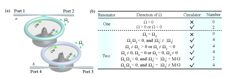
In this paper, we propose how to realize a single-photon circulator with multiple frequency points in a system composed of two spinning whispering-gallery-mode (WGM) resonators and two waveguides. As shown in Fig. 1(a), we consider two spinning WGM microresonators and , coupled to two waveguides a and b, with four input/output ports, respectively. The WGM holds two cavity modes corresponding to clockwise (CW) and counterclockwise (CCW) modes with frequencies and , respectively. When the resonator spins at an angular velocity , the rotation-induced Sagnac-Fizeau shift is given by [62, 92]
| (1) |
where is the intrinsic frequency of the nonspinning resonator, and are the propagation speed and wavelength of light, and are the radius and reflectivity of the resonator, respectively. The dispersion term , characterizing the relativistic origin of the Sagnac shift, is relatively small in typical materials () [92]. () indicates CW (CCW) rotation of the resonator.
() is the rotational angular velocity of the () resonator, and () is the Sagnac shift due to the rotation of the () resonator. Under the rotating wave approximation, the total Hamiltonian can be written as ()
| (2) |
Here, the first term describes the free part,
| (3) | |||||
where () is the effective frequency for travelling modes in the () resonator. () is the creation operators in the ()resonator. () is the creation operators for the right-moving (left-moving) photon along the waveguide at position . () is the creation operators for the right-moving (left-moving) photon along the waveguide at position . The group velocities have been assumed to be . The second terms in Eq. (1) describes the interacting part.
| (4) | |||||
where () is the () resonator and () waveguide coupling strength. is the coupling strength of resonator and .
In the case of a single excitation, the state vector of the system can be written as
| (5) | |||||
where is the vacuum state which indicates that there is zero photon in both the waveguide and the resonator. () is the probability amplitude of a photon appearing in () resonator. (, ) is the probability amplitude of the right- or left-moving photon in the waveguide a (b). According to the Schrdinger equation , and removing and , the coupled equations can be written
| (6) |
The photon enters through port 1 of the waveguide, and the wave function is
| (7) |
where represents the probability amplitude of photon transmission from port to port . is a step function. The transmission probability is defined by
| (8) |
Combine Eq. (6) and Eq. (7), we obtain the transmission probability amplitude
| (9) | |||||
| (10) | |||||
| (11) |
where is detuning. Since the direction of photon transmission is opposite to the direction of the CCW mode in resonator, . Similarly, since the CW mode of the resonator is only coupled to the CCW mode of the resonator, . So, it is easily to find that which guarantees the probability conservation for the incident photon.
If the photon enters through port 2 of the waveguide, and the wave function is
| (12) |
The probability amplitude can be obtained by combining Eqs. (6) and (12)
| (13) | |||||
| (14) | |||||
| (15) |
Using the same method, we can also obtain transmission probabilities , , and . They satisfy the relationships , , and . From Eqs. (10-11) and (14-15), it can be observed that if and , we can observe that , . That is to say, when two resonators are static () or rotate with the same angular velocity (), the photon transmission in the same waveguide is reciprocal.
3 A Single-Photon Circulator Made of Two Spinning Optical Resonators
In this section, the main focus of these results is to analyze how different spinning direction in the resonator can impact the frequency of the realized photon circulator. For this purpose, we will focus on the following cases: 1) One resonator spins while the other remains static. 2) Both resonators spin in the same direction. 3) Both resonators spin in opposite directions. In our calculations, we have selected the experimentally feasible parameters [93, 94, 95]: m, , , m, , , m/s, and MHz.
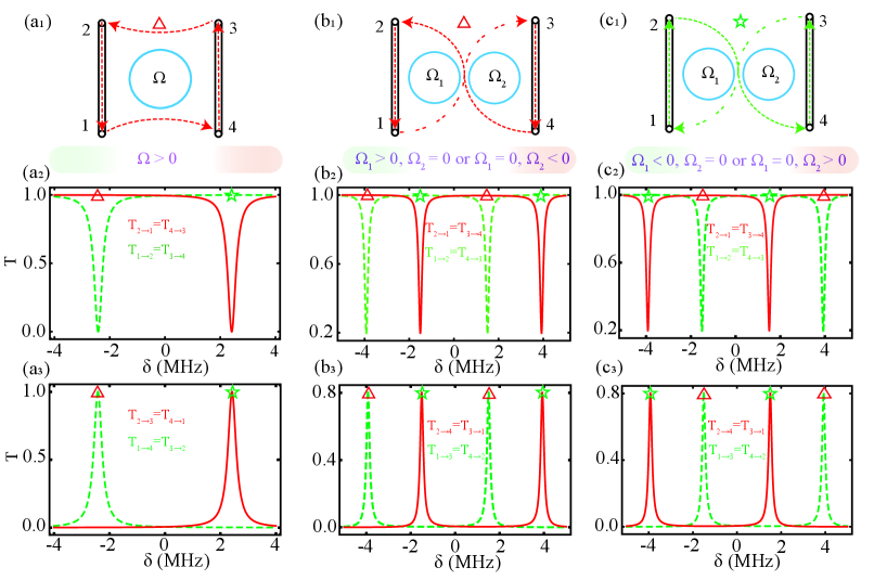
For comparisons, we first consider the single resonator case illustrated in Fig. 2(). In Figs. 2() and 2(), transmission probability distribution as a function of detuning for single resonator. The photon transmitted with circulation in the counterclockwise direction , at [see Fig. 2()]. In addition, the photon also can transmit with circulation in the clockwise direction , at . The above circulation can be seen from the transmission spectra as shown in Fig. 2(-). The results are consistent with those in Ref. [78].
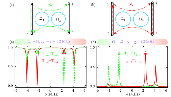
For two resonators case with and (or and ), when , the photon transmitted with circulation in the reverse -word direction , see Fig. 2() (The position marked by a red triangle). The circulation can be seen from the transmission spectra as shown in Figs. 2(-). In this case, the photon can not be transmitted from ports 2 and 3 to ports 4 and 1 , respectively. Due to the large frequency detuning, the photon entering from port 2 can not be transmitted to the CCW mode of the resonator. It also cannot couple with the CW mode of the resonator, as the direction of photon transmission is opposite to it. So that the photon from port 2 transmits through the waveguide directly to port 1. Also, because of the large frequency detuning, the photon entering from port 3 can not be transmitted to the CW mode of the resonator. It also cannot couple with the CCW mode of the resonator, as the direction of photon transmission is opposite to it. So that the photon from port 3 transmits through the waveguide directly to port 4. In contrast, the photon entering from port 1 (4) couples to the CW (CCW) travelling mode with the couping , so that the photon can be transferred to port 3 (2). Therefore, four frequency point photon circulators can be achieved in this system.
The circulator can also be in the direction of a positive character, i.e. , at , see Fig. 2() (The position marked by a green star). The routing behavior can be understood in a similar way as given above. The photon can not be transmitted from ports 1 and 4 to ports 4 and 2 , respectively. Due to the large frequency detuning, the photon entering from port 1 can not be transmitted to the CW mode of the resonator. It also cannot couple with the CCW mode of the resonator, as the direction of photon transmission is opposite to it. So that the photon from port 1 transmits through the waveguide directly to port 2. The photon entering from port 4 can not be transmitted to the CCW mode of the resonator. It also cannot couple with the CW mode of the resonator, as the direction of photon transmission is opposite to it. So that the photon from port 4 transmits through the waveguide directly to port 3. In contrast, the photon entering from port 2 (3) couples to the CCW (CW) travelling mode with the couping , so that the photon can be transferred to port 4 (1). In addition, when and (or and ), we have plotted the transmission probability distribution as a function of detuning , as shown in Fig. 2(-). We found that Fig. 2(-) is mirror symmetric in Fig. 2(-) with as the mirror surface.
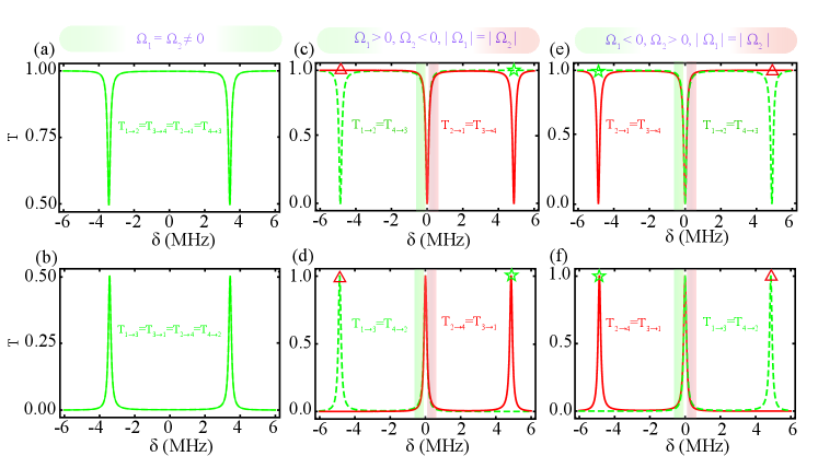
Then, we consider the photon transmission spectra of two resonators rotating in the same directions (e.g., ), as shown in the Figs. 3(a-b). Consistent with our previous calculation results, the probability of phohton transmission from any port is , and the photon transmission is reciprocal in the same waveguide. In Figs. 3(c-f), we have plotted the photon transmission spectra of two resonator rotating in opposite directions, e.g., , , and or , , and . Here, we found that a frequency point () can achieve an reverse or positive circulator, which means to realize the two photon circulator frequency point. Besides, we also found that at a specific angular velocity (, ), there was one frequency point that the photon entering from any waveguide can be completely routed to the other waveguide. We also found that Figs. 3(c-d) is mirror symmetric in Figs. 3(e-f) with as the mirror surface.
Comparad to a single resonator case, two resonators can have four frequency points for photon circulators, due to the coupling between resonators caused energy level splitting and the Fizeau drag induced splitting of the resonance frequencies of the two counter-travelling optical modes. In addition, we also found that there was one frequency point that the photon entering from any waveguide can be completely routed to the other waveguide. The direction of the photon circulator has also changed, form clockwise (counterclockwise) to reverse (positive) 8-word. The different directions of the photon circulator are due to the coupling between the CW (CCW) mode of the resonator and the CCW (CW) mode of the resonator.
4 Backscattering Effect
The WGM resonators has two degenerate modes corresponding to CW and CCW modes. In practical devices, backscattering is unavoidable. They may be coupled together if the surface of the resonator is rough or the material is uneven[96, 97, 98]. So the Hamiltonian of the system is added with a term
where () is the coupling strength of CW and CCW modes inside the resonator due to backscatter. Using the same method as in the previous section, we can calculate the probability for each port. Figure 4 shows the probability of the photon transitioning from port 1 to port 3 under different conditions.
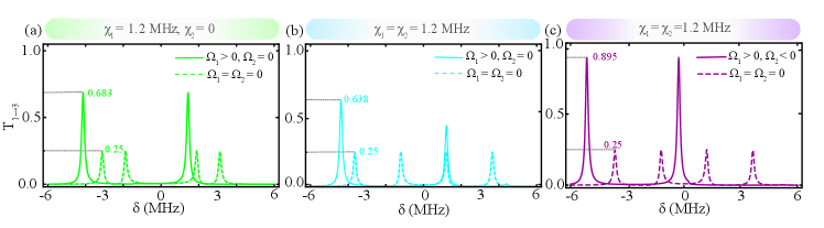
In Fig. 4(a), the dashed line indicates no rotation, but the resonator has backscattering, e.g. MHz, . The solid line indicates rotation of the resonator under the condition of the dashes line, e.g. MHz, . We found that the maximum value of increased from 0.25 to 0.683. So the results indicate that rotation is robust against backscattering. We also found that the frequency points that can be transmitted have shifted to the left, which is caused by the clockwise rotation of the resonator. On the contrary, when the resonator rotates counterclockwise, the transmission frequency point shift to the right. In Fig. 4(b), the dashed line indicates that both resonators are static but have backscattering, e.g. , MHz. In contrast to Figure 4(a) a resonator has backscatter, we found that adding backscattering in another resonator does not change the value of , bacause the four ports are transmitted with equal paobability. In the case of backscatter in both resonators, the soild line indicates tthe resonator rotates clockwise and the resonator static, e.g. , , MHz. The maximum value of has decreased from 0.683 to 0.638. This is cauesd by the backscatter of the resonator. When the resonator rotates clockwise and the resonator rotates counterclockwise (, , ), the transmission probability can reach 0.895, as shown in Fig. 4(c). In addition, if , , , its transmission spectrum can be obtained in Fig. 4(b) though mirror reflection symmetry with as the mirror surface.
In the previous section, when the rotational angular velocities of the two resonators are equal and the direction is the same, the photon transmission is reciprocal in the same waveguide. Here, due to the addition of backscattering, we have broken this reciprocity. In Fig. 5, the transmission spectra of photons are plotted by adding backscattering to the resonators when the rotational angular velocities of the two resonators are equal and the direction is the same. We found two frequency points that can implement a single photon circulator, and the routing behavior is shown in Figs. 5(a-b). The circulator can be seen from the transmission spectra as shown in Figs. 5(c-d). Unlike the 8-word circulator, the direction of the circulator is clockwise or counterclockwise circulator.
5 Conclusion
We studied the coherent transmission of a single photon in a coupled system of two rotating WGM resonators and two waveguides. This system could form a four-port circulator, whose routing direction depended on the frequency of the incident photon, and the direction of rotation of the two resonators. We found that when both resonators rotated at identical angular velocities, single-photon transmission exhibited reciprocity within the same waveguide. When the angular velocities differed, usually there were four frequency points capable of facilitating single-photon circulation. However, when two resonators rotated in opposite directions with equal angular velocities, besides photon circulates at two frequency points, there is one frequency point at which a single photon input from any waveguide is completely routed to another. When the backscattering of a resonator is present, the single-photon circulation suppressed by the internal defect-induced backscattering can be restored by rotating the resonator, which is witnessed by enhancement of the probability of a single photon transfer.
We note that the presence of the reciprocity shut down the circulator for photons with arbitrary frequency. To turn on the circulator, the resonator must rotate at different angular velocities, so that the reciprocity of photon transmission is broken. Furthermore, one can tune the angular velocity to turn on or off circulating photons with a given frequency. The nonreciprocity of quantum circulators can be used to design novel quantum photonic device, which may have extensive applications in future quantum technologies.
Funding This work was supported by NSFC Grants No.11935006, No. 12075082, No. 12247105, No. 12205054, the science and technology innovation Program of Hunan Province (Grant No. 2020RC4047), National Key R D Program of China (No. 2024YFE0102400), the Hunan Provincial major Sci-Tech Program (2023ZJ1010) and PH. D. Research Foundation (BSJJ202122). \bmsectionDisclosures The authors declare no conflicts of interest.
References
- [1] C. C. Xia, X. B. Yan, X. D. Tian, and F. Gao, "Ideal optical isolator with a two-cavity optomechanical system," Opt. Commun. 451, 197-201, (2019).
- [2] D. Jalas, A. Petrov, M. Eich, W. Freude, S. H. Fan, Z. F. Yu, R. Baets, M. Popovi, A. Melloni, J. D. Joannopoulos, M. Vanwolleghem, C. R. Doerr and H. Renner, "What is-and what is not-an optical isolator," Nat. Photonics 7, 579-582, (2013).
- [3] B. J. H. Stadler and T. Mizumoto, "Integrated Magneto-Optical Materials and Lsolators: A Review," IEEE Photonics Jourbal 6, 1-15, (2014).
- [4] F. Ruesink, J. P. Mathew, M. A. Miri, A. Al, and E. Verhagen, "Optical circulation in a multimode optomechanical resonator," Nat. Commun. 9, 1798, (2018).
- [5] R. Navarathna, D. T. Le, A. R. Hamann, H. D. Nguyen, T. M. Stace, and A. Fedorov, "Passive Superconducting Circulator on a Chip," Phys. Rev. Lett. 130, 037001 (2023).
- [6] B. G. Xu, D. G. Zhang, Y. Wang, B. B. Hong, G. X. Shu and W. L. He, "A Terahertz circulator Based on Magneto Photonic Crystal Slab," Photonics 10, 360 (2023).
- [7] C. Jiang, L. N. Song, and Y. Li. "Directional amplifier in an optomechanical system with optical gain," Phys. Rev. A 97, 053812 (2018).
- [8] L. J. Aplet and J. W. Carson, "A Faraday Effect Optical Isolator," Applied Optics, 3, 544-545 (1964).
- [9] W. Y. Qiu, X. H. Cheng, A. X. Chen, Y. Y. Lan, and W. J. Nie, "Controlling quantum coherence and entanglement in cavity magnomechanical systems," Phys. Rev. A 105, 063718 (2022).
- [10] G. Viola and D. P. DiVincenzo, "Hall Effect Gyrators and Circulators," Phys. Rev. X 4, 021019 (2014).
- [11] L. Fan, J. Wang, L. T. Varghest, H. Shen, B. Niu, Y. Xuan, A. M. Weiner, and M. Qi, "An All-Silicon Passive Optical Diode," Science 335, 447-450 (2012).
- [12] S. Y. Hua, J. M. Wen, X. S. Jiang, Q. Hua, L. Jiang and M. Xiao, "Demonstration of a chip-based optical isolator with parametric amplification," Nat. Commun. 7, 13657 (2016).
- [13] Q. T. Cao, H. M. Wang, C. H. Dong, H. Jing, R. S. Liu, X. Chen, L. Ge, Q. H. Gong, and Y. F. Xiao, "Experimental Demonstration of Spontaneous Chirality in a Nonlinear Microresonator," Phys. Rev. Lett. 118, 033901 (2017).
- [14] X. Y. Zhang, Q. T. Cao, Z. Wang, Y. X. Liu, C. W. Qiu, L. Yang, Q. H. Gong and Y. F. Xiao, "Symmetry-breaking-induced nonlinear optics at a microcavity surface," Nat. Photonics 13, 21-24 (2019).
- [15] P. F. Yang, M. Li, X. Han, H. He, G. Li, C. L. Zou, P. F. Zhang, Y. H. Qian, and T. C. Zhang, "Non-Reciprocal Cavity Polarition with Atoms Strongly Coupled to Optical Cavity," Laser Photonics Rev. 17, 2200574 (2023).
- [16] S. Manipatruni, J. T. Robinson, and M. Lipson, "Optical Nonreciprocity in Optomechanical Structures," Phys. Rev. Lett. 102, 213903 (2009).
- [17] Z. X. Tang, and X. W. Xu, "Multiterminal nonreciprocal routing in an optomechanical plaquette via synthetic magnetism," New J. Phys. 25, 123028 (2023).
- [18] M. Hafezi and P. Rabl, "Optomechanically induced non-reciprocity in microring resonators," Opt. Express 20, 7672-7684 (2012).
- [19] S. J. M. Habraken, K. Stannigel, M. D. Lukin, P. Zoller and P. Rabl, "Continuous mode cooling and phonon routers for phononic quantum networks," New J. Phys. 14, 115004 (2012).
- [20] M. Schmidt, S. Kessler, V. Peano, O. Painter, and F. Marquardt, "Optomechanical creation of magnetic felds for photons on a lattice," Optica 2, 635-641 (2015).
- [21] A. Metelmann, and A. A. Clerk, "Nonreciprocal photon transmission and amplifcation via reservoir engineering," Phys. Rev. X 5, 021025 (2015).
- [22] X. W. Xu, and Y. Li, "Optical nonreciprocity and optomechanical circulator in three-mode optomechanical systems," Phys. Rev. A 91, 053854 (2015).
- [23] X. W. Xu, Y. Li, A. X. Chen, and Y. X. Liu, "Nonreciprocal conversion between microwave and optical photons in electro-optomechanical systems," Phys. Rev. A 93, 023837 (2016).
- [24] Z. Shen, Y. L. Zhang, Y. Chen, C. L. Zou, Y. F. Xiao, X. B. Zou, F. W. Sun, G. C. Guo and C. H. Dong, "Experimental realization of optomechanically induced non-reciprocity," Nat. Photonics 10, 657-661 (2016).
- [25] F. Ruesink, M. A. Miri, A. Al, and E. Verhagen, "Nonreciprocity and magnetic-free isolation based on optomechanical interactions," Nat. Commun. 7, 13662 (2016).
- [26] E. Verhagen, and A. Ai, "Optomechanical nonreciprocity," Nat. Phys. 13, 922-924 (2017).
- [27] K. Fang, J. Luo, A. Metelmann, M. H. Matheny, F. Marquardt, A. A. Clerk, and O. Painter, "Generalized non-reciprocity in an optomechanical circuit via synthetic magnetism and reservoir engineering," Nat. Phys, 13, 465-471 (2017).
- [28] G. A. Peterson, F. Lecocq, K. Cicak, R. W. Simmonds, J. Aumentado, and J. D. Teufel, "Demonstration of efficient nonreciprocity in a microwave optomechanical circuit," Phys. Rev. X 7, 031001 (2017).
- [29] N. R. Bernier, L. D. Toth, A. Koottandavida, M. A. Ioannou, D. Malz, A. Nunnenkamp, A. A. K. Feofanov and T. J. Kippenberg, "Nonreciprocal reconfigurable microwave optomechanical circuit," Nat. Commun. 8, 604 (2017).
- [30] S. Barzanjeh, M. Wulf, M. Peruzzo, M. Kalaee, P. B. Dieterle, O. Painter, and J. M. Fink, "Mechanical on-chip microwave circulator," Nat. Commun. 8, 953 (2017).
- [31] L. Tian and Z. Li, "Nonreciprocal quantum-state conversion between microwave and optical photons," Phys. Rev. A 96, 013808 (2017).
- [32] C. Jiang, L. N. Song and Y. Li, "Directional amplifer in an optomechanical system with optical gain," Phys. Rev. A 97, 053812 (2017).
- [33] H. Xu, L. Jiang, A. A. Clerk and J. G. E. Harris, "Nonreciprocal control and cooling of phonon modes in an optomechanical system," Nature 568, 65-69 (2019).
- [34] L. M. d. Lpinay, E. Damskgg, C. F. Ockeloen-Korppi, and M. A. Sillanp, "Realization of directional amplifcation in a microwave optomechanical device," Phys. Rev. Appl. 11, 034027 (2019).
- [35] D. G. Lai, J. F. Huang, X. L. Yin, B. P. Hou, W. Li, D. Vitali, F. Nori and J. Q. Liao, "Nonreciprocal ground-state cooling of multiple mechanical resonators," Phys. Rev. A 102, 011502 (2020).
- [36] X. Xu, Y. Zhao, H. Wang, H. Jing, and A. Chen, "Quantum nonreciprocality in quadratic optomechanics," Photon. Res. 8, 143-150 (2020).
- [37] Y. Chen, Y. L. Zhang, Z. Shen, C. L. Zou, G. C. Guo and C. H. Dong, "Synthetic gauge fields in a single optomechanical resonator," Phys. Rev. Lett. 126, 123603 (2021).
- [38] J. X. Liu, Y. F. Jiao, Y. Li, X. W. Xu, Q. Y. He, and H. Jing, "Phase-controlled asymmetric optomechanical entanglement against optical backscattering," Sci. China-Phys. Mech. Astron. 66, 230312 (2023).
- [39] T. X. Lu, Y. Wang, K. Y. Xia, L. M. Kuang, and H. Jing, "Quantum squeezing induced nonreciprocal photon laser," Sci. China-Phys. Mech. Astron. 67, 6 (2024).
- [40] W. Zhao, S. D. Zhang, A. Miranowicz, and H. Jing, "Weak-force sensing with squeezed optomechanics," Sci. China-Phys. Mech. Astron. 63, 224211 (2020).
- [41] L. L. Zheng, X. H. Xiong, X. Y. Guo, D. W. Zhang, and X. Y. L, "Nanoparticle detection based on microcavity exceptional-point characteristics," Phys. Rev. A 109, 013502 (2024).
- [42] D. W. Zhang, L. L. Zheng, M. Wang, Y. Zhou, and X. Y. L, "Loss-induced chaos in double-cavity optomechanical system," Phys. Rev. A 109, 023529 (2024).
- [43] X. Y. L, H. Jing, J. Y. Ma, and Y. Wu, "PT-Symmetry-Breaking Chaos in optomechanics," Phys. Rev. Lett. 114, 253601 (2015).
- [44] C. E. Rter, K. G. Makris, R. El-Ganainy, D. N. Christodoulides, M. Segev, and D. Kip, "Observation of paritytime symmetry in optics," Nat. Phys. 6, 192-195 (2010).
- [45] J. H. Wu, M. Artoni, and G. C. L. Rocca, "Non-Hermitian Degeneracies and Unidirectional Reflectionless Atomic Lattices," Phys. Rev. Lett. 113, 123004 (2014).
- [46] N. Bender, S. Factor, J. D. Bodyfelt, H. Ramezani, D. N. Christodoulides, F. M. Ellis, and T. Kottos, "Observation of asymmetric transport in structures with active nonlinearities," Phys. Rev. Lett. 110, 234101 (2013).
- [47] B. Peng, Ş. K. zdermir, F. Lei, F. Monifi, M. Gianfreda, G. L. Long, S. Fan, F. Nori, C. M. Bender and L. Yang, "Parity-time-symmetric whispering-gallery microcavities," Nat. Phys. 10, 394-398 (2014).
- [48] L. Chang, X. S. Jiang, S. Y. Hua, C. Yang, J. M. Wen, L. Jiang, G. Z. Wang and M. Xiao, "Parity-time symmetry and variable optical isolation in active-passive-coupled microresonators," Nat. Photonics 8, 524 (2014).
- [49] H. Zhang, R. Huang, S. D. Zhang, Y. Li, C. W. Qiu, F. Nori, and H. Jing, "Breaking anti-PT symmetry by spinning a resonator," Nano Lett. 20, 7594-7599 (2020).
- [50] F. Wang, X. Niu, X. Hu, T. Gu, X. Wang, J. Yang, H. Yang, Y. Ao, S. Wang and Q. Gong, "All-Optical Mode-Selective Router Based on Broken Anti-PT Symmetry," Phys. Rev. Appl. 14, 044050 (2020).
- [51] D. W. Wang, H. T. Zhou, M. J. Guo, J. X. Zhang, J. Evers and S. Y. Zhu, "Optical diode made from a moving photonic crystal," Phys. Rev. Lett. 110, 093901 (2013).
- [52] S. A. R. Horsley, J. H. Wu, M. Artoni and G. C. La Rocca, "Optical nonreciprocity of cold atom bragg mirrors in motion," Phys. Rev. Lett. 110, 223602 (2013).
- [53] H. Ramezani, P. K. Jha, Y. Wang and X. Zhang, "Nonreciprocal localization of photons," Phys. Rev. Lett. 120, 043901 (2018).
- [54] S. Zhang, Y. Hu, G. Lin, Y. Niu, K. Xia, J. Gong and S. Gong, "Thermal-motion-induced non-reciprocal quantum optical system," Nat. Photonics 12, 744-748 (2018).
- [55] K. Xia, F. Nori and M. Xiao, "Cavity-free optical isolators and circulators using a chiral cross-kerr nonlinearity," Phys. Rev. Lett. 121, 203602 (2018).
- [56] G. Lin, S. Zhang, Y. Hu, Y. Niu, J. Gong and S. Gong, "Nonreciprocal amplification with four-level hot atoms," Phys. Rev. Lett. 123, 033902 (2019).
- [57] C. Liang, B. Liu, A. N. Xu, X. Wen, C. Lu, K. Xia, M. K. Tey, Y. C. Liu and L. You, "Collision-induced broadband optical nonreciprocity," Phys. Rev. Lett. 125, 123901 (2020).
- [58] E. Z. Li, D. S. Ding, Y. C. Yu, M. X. Dong, L. Zeng, W. H. Zhang, Y. H. Ye, H. Z. Wu, Z. H. Zhu, W. Gao, G. C. Guo and B. S. Shi, "Experimental demonstration of cavity-free optical isolators and optical circulators," Phys. Rev. Res. 2, 033517 (2020).
- [59] X. X. Hu, Z. B. Wang, P. Zhang, G. J. Chen, Y. L. Zhang, G. Li, X. B. Zou, T. Zhang, H. X. Tang, C. H. Dong, G. C. Guo and C. L. Zou, "Noiseless photonic non-reciprocity via optically-induced magnetization," Nat. Commun. 12, 2389 (2021).
- [60] H. Jing, H. L, S. K. zdemir, T. Carmon and F. Nori, "Nanoparticle sensing with a spinning resonator," Optica. 5, 1424-430 (2018).
- [61] A. Graf, S. D. Rogers, J. Staffa, U. A. Javid, D. H. Griffith, and Q. Lin, "Nonreciprocity in Photon Pair Correlations of Classically Reciprocal Systems," Phys. Rev. Lett. 128, 213605 (2022).
- [62] S. Maayani, R. Dahan, Y. Kligerman, E. Moses, A. U. Hassan, H. Jing, F. Nori, D. N. Christodoulides and T. Carmon, "Flying couplers above spinning resonators generate irreversible refraction." Nature 558, 569-572 (2018).
- [63] Y. Li, Y. F. Peng, L. Han, M. A. Miri, W. Li, M. Xiao, X. F. Zhu, J. Zhao, A. Al, S. H. Fan, and C. W. Qiu, "Anti-parity-time symmetry in diffusive systems," Science 364, 170-173 (2019).
- [64] X. Mao, H. Yang, D. Long, M. Wang, P. Y. Wen, Y. Q. Hu, B. Y. Wang, G. Q. Li, J. C. Gao, and G. L. Long, "Experimental demonstration of made-matching and Sagnac effect in a millimeter-scale wedged resonator gyroscope," Photon. Res. 10, 2115-2121 (2022).
- [65] P. P. Khial, A. D. White and A. Hajimiri, "Nanophotonic optical gyroscope with reciprocal sensitivity enhancement," Nat. Photonics 12, 671-675 (2018).
- [66] R. Huang, A. Miranowicz, J. Q. Liao, F. Nori and H. Jing, "Nonreciprocal photon blockade," Phys. Rev. Lett. 121, 153601 (2018).
- [67] B. Li, R. Huang, X. W. Xu, A. Miranowicz, and H. Jing, "Nonreciprocal unconventional photon blockade in a spinning optomechanical system," Photon. Res. 7, 630-641 (2019).
- [68] K. Wang, Q. Wu, Y. F. Yu, and Z. M. Zhang, "Nonreciprocal photon blockade in a two-mode cavity with a second-order nonlinearity," Phys. Rev. A 100, 053832 (2019).
- [69] H. Z. Shen, Q. Wang, J. Wang, and X. X. Yi, "Nonreciprocal unconventional photon blockade in a driven dissipative cavity with parametric amplifcation," Phys. Rev. A 101, 013826 (2020).
- [70] W. S. Xue, H. Z. Shen, and X. X. Yi, "Nonreciprocal conventional photon blockade in driven dissipative atom-cavity," Opt. Lett. 45, 4424-427 (2020).
- [71] Y. W. Jing, H. Q. Shi, and X. W. Xu, "Nonreciprocal photon blockade and directional amplifcation in a spinning resonator coupled to a two-level atom," Phys. Rev. A 104, 033707 (2021).
- [72] Y. Jiang, S. Maayani, T. Carmon, F. Nori, and H. Jing, "Nonreciprocal phonon laser," Phys. Rev. Appl. 10, 064037 (2018).
- [73] Y. Xu, J. Y. Liu, W. Liu, and Y. F. Xiao, "Nonreciprocal phonon laser in a spinning microwave magnomechanical system," Phys. Rev. A 103, 053501 (2021).
- [74] Y. F. Jiao, S. D. Zhang, Y. L. Zhang, A. Miranowicz, L. M. Kuang, and H. Jing, "Nonreciprocal Optomechanical Entanglement against Backscattering Losses," Phys. Rev. Lett. 125, 143605 (2020).
- [75] B. J. Li, S. K. zdemir, X. W. Xu, L. Zhang, L. M. Kuang, and H. Jing, "Nonreciprocal optical solitons in a spinning Kerr resonator," Phys. Rev. A 103, 053522 (2021).
- [76] N. Hu, Z. X. Tang, and X. W. Xu, "Broadband optical nonreciprocity via nonreciprocal band structure," Phys. Rev. A 108, 063516 (2023).
- [77] J. S. Yang, W. Nei, M. Chen, X. Su, Y. Q. Lu, F. Nori, and K. Y. Xia, "Nonreciprocal Single-Photon Band Structure," Phys. Rev. Lett. 126, 203602 (2022).
- [78] Y. W. Jing, "Quantum spining photonic circulator", Scientific Reports 12, 5844, (2020).
- [79] J. Kerckhof, K. Lalumire, B. J. Chapman, A. Blais, and K. W Lehnert, "On-chip superconducting microwave circulator from synthetic rotation," Phys. Rev. Appl. 4, 034002 (2015).
- [80] K. M. Sliwa, M. Hatridge, A. Narla, S. Shankar, L. Frunzio, R. J. Schoelkopf, and M. H. Devoret, "Reconfgurable josephson circulator/directional amplifer," Phys. Rev. X 5, 041020 (2015).
- [81] B. J. Chapman, E. I. Rosenthal, J. Kerckhoff, B. A. Moores, L. R. Vale, J. A. B. Mates, G. C. Hilton, K. Lalumire, A. Blais, and K. W. Lehnert, "Widely tunable on-chip microwave circulator for superconducting quantum circuits," Phys. Rev. X 7, 041043 (2017).
- [82] C. Mller, S. W. Guan, N. Vogt, J. H. Cole, and T. M. Stace, "Passive on-chip superconducting circulator using a ring of tunnel junctions," Phys. Rev. Lett. 120, 213602 (2018).
- [83] Z. Shen, Y. L. Zhang, Y. Chen, F. W. Sun, X. B. Zou, G. C. Guo, C. L. Zou and C. H. Dong, "Reconfgurable optomechanical circulator and directional amplifer," Nat. Commun. 9, 1797 (2018).
- [84] M. Scheucher, A. Hilico, E. Will, J. Volz, and A. Rauschenbeutel, " Quantum optical circulator controlled by a single chirally coupled atom," Science 354, 1577-1580 (2016).
- [85] X. W. Xu, A. X. Chen, Y. Li, and Y. X. Liu, "Single-photon nonreciprocal transport in one-dimensional coupled-resonator waveguides," Phys. Rev. A 95, 063808 (2017).
- [86] X. W. Xu, A. X. Chen, Y. Li, and Y. X Liu, "Nonreciprocal single-photon frequency converter via multiple semi-infnite coupled resonator waveguides," Phys. Rev. A 96, 053853 (2017).
- [87] X. W. Xu, Y. Li, B. Li, H. Jing, and A. X. Chen, "Nonreciprocity via nonlinearity and synthetic magnetism," Phys. Rev. Appl. 13, 044070 (2020).
- [88] I. M. Georgescu, S. Ashhab, and F. Nori, "Quantum simulation," Rev. Mod. Phys. 86, 153-185 (2014).
- [89] G. Q. Xu, K. C. Dong, Y. Li, H. G. Li, K. P. Liu, L. Q. Li, J. Q. Wu, and C. W. Qiu, "Tunable analog thermal material," Nat. Commun. 11, 6028 (2020).
- [90] M. Cromb, G. M. Gibson, E. Toninelli, M. J. Padgett, E. M. Wright, and D. Faccio, "Amplification of waves from a rotating body," Nat. Phys. 16, 1069-1073 (2020).
- [91] C. X. Zhang, X. Jiang, and D. Ta, "Revealing the incidence-angle-independent frequency shift in the acoustic rotational doppler effect," Phys. Rev. Lett. 132, 114001 (2024).
- [92] G. B. Malykin, "The Sagnac effect: Correct and incorrect explanations," Phys.-Usp. 43, 1229 (2000).
- [93] K. J. Vahala, "Opitical microcavities," Nature 424, 839-846, (2003).
- [94] S. M. Spillane, T. J. Kippenberg, K. J. vahala, K. W. Goh, E. Wilcut, and H. J. Kimble, "Ultrahigh-Q toroidal microresonators for cavity quantum electrodynamics," Phys. Rev. A 71, 013817 (2005).
- [95] T. K Aoki, B. Dayan, E. Wilcut, W. P. Bowen, A. S. Parkins, T. J. Kippenberg, K. J. Vahala and H. J. Kimble, "Observation od strong coupling between one atom and a monolithic microresonator," Nature 443, 671-674 (2006).
- [96] J. G. Zhu, S. H. K. Ozdemir, Y. F. Xiao, L. Li, L. N. He, D. R. Chen, and L. Yang, "On-chip single nanoparticle detection and sizing by mode splitting in an ultrahigh-Q microresonator," Nat. Photonics 4, 46-49 (2010).
- [97] Q. Guo, K. X. Zhou, C. H. Bai, Y. C. Zhang, G. Li, and T. C. Zhang, "Nonreciprocal mechanical squeezing in a spinning cavity optomechanical system via pump modulation," Phys. Rev. A 108, 033515 (2023).
- [98] Y. F. Jiao, S. D. Zhang, Y. L. Zhang, A. Miranowicz, L. M. Kuang, and H. Jing, "Nonreciprocal Optomechanical Entanglement against Backscattering Losses," Phys. Rev. Lett. 125, 143605 (2020).