Negative refraction with little loss manipulated by the voltage and pulsed laser in double quantum dots
Abstract
The paper demonstrates that negative refractive index can be achieved via tuning the tunneling rate between a double quantum dots(QDs) system by applying a bias voltage, and a pulsed laser. As the bias voltage being changed, the refraction index can be tunable to negative with the simultaneous negative permittivity and permeability. While the varying pulsed laser is applied to the double QDs system, moreover, the negative refractive index with little loss can be obtained. The flexible manipulation on a solid state system to realize negative refraction may give a new way for experimental research in the future.
- PACS:
-
78.20.Ci, 42.50.Gy
I Introduction
Negative refraction materialsRef1 ,which originally suggested by Veselago attracted impressive efforts to be investigated during the past decades. Materials with negative refractive index promise many surprising and even counterintuitive electromagnetical and optical effects such as the negative Goos-Hnchen shiftRef2 , amplification of evanescent wavesRef3 , reversals of both Doppler shift and Cerenkov radiationRef2 , sub-wavelength focusingRef5 and so on. And there have been many approaches to realize materials with negative refractive index, which can be summarized as artificial structures such as metamaterials Ref6 and photonic crystalsRef7 , chiral materialsRef8 and photonic resonant mediaRef9 -Ref10 . The scheme of photonic resonant media firstly brought forth by M..OktelRef9 discussed how a three-level atomic gas system to realize optical modification of magnetic permeability and then possibly to obtain left-handed electrodynamics. It found that it is in principle possible to electromagnetically induce left-handedness to a spatially homogeneous media. The major challenge for the scheme is to have two levels separated at optical frequencies while having a nonvanishing magnetic dipole matrix element. Such level splitting requires large external magnetic fields or should be engineered by other means such as external electric fields or spin-orbital couplings. Therefore, we can consider solid state systemsRef9 , and try to utilize excitonic energy levels in solid state heterostructures to engineer three-level system satisfying the energy condition.
Thus, from the point of against the challenge, QDs with a suitable spectrum may be the candidate. QDs provide a three-dimensional confinement of carriers,in which electrons and holes can occupy only a set of states with discrete energies, and can thus be used to perform “atomic physics”experiments in solid-state structures. One advantage of QD¡¯s is that allow the control of direct quantum-mechanical electronic coupling with not only composition but externally applied voltages. These flexible systems represent therefore the ideal for theoretical and experimental investigations, where the interactions between light and matter can be studied in a fully controlled, well characterized environment, and with excellent optical and electrical probes. These features make semiconductor QD¡¯s promising candidates for applications in electro-optical devices such as QD lasersRef22 -Ref23 and in quantum information processingRef24 -Ref25 . In the latter case, one can exploit the optical excitation in a QDRef24 , or its spin stateRef25 , as qubits. The ability to assemble collections of QD¡¯s with designed geometries opens up a number of interesting possibilities.
The aim of this paper is to explore the feasibility that negative refractive index can be achieved by tuning the tunneling rate between the double QD system via applying an external bias voltage, and an optical pump pulse. Via the bias voltage one can suppress or enhance the tunneling rate between the two dots. As the tunneling rate is changed, the double quantum dot system is tunable to left-handedness with simultaneous negative permittivity and permeability. Varying the intensity of the pulsed laser, the quantum dot system can also show left-handedness with negative refractive index. Moreover, the negative refractive index and little loss can be achieved at the same time.
In the present paper, the model system is introduced in the next section. In Sec.III, the results of our calculations for two different conditions are presented by varying the bias voltage and the intensity of the pulse. Finally, we give a summary of our results and conclusions in Sec.IV.
II Model System
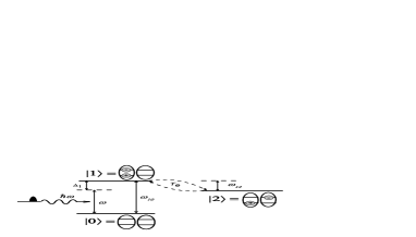
A schematic representation of the Hamiltonian for our model is shown in Figure 1. The double QDs consists of the left and the right dots with different band structures coupled by tunneling in our model system. In the setup, the self-assembled lateral QD molecules were produced on GaAs(0,0,1) substrates by a unique combination of molecule beam epitaxy and in situ atomic layer precise etchingRef11 -Ref13 which provides a low density homogeneous ensembles of QD molecules consisting of two dots aligned along the [1,,0] direction. The lateral quantum coupling between two self-assembled (In,Ga)As quantum dots has been observedRef12 , and it demonstrated that the QD molecule is composed of two distinct QDs, even though the QDs are separated by only a few nanometers of barrier material. And we know that for the QD’s separation d 9nm the electron tunnel coupling energy between the two dots is smaller as compared to the electron-hole Coulomb interaction energy and the exciton states can readily be described in terms of a simplified single-particle pictureRef14 -Ref16 . Because the nanoscale interdot separation, the exciton states consist of delocalized electron states, i.e., holes are localized in the QDs, while electrons become almost entirely delocalized in the QD moleculesRef12 . By applying electromagnetic field we can excite one electron from the valence to the conduction band in the left dot, which can in turn tunnel to the right one. Applying a bias voltage, we can adjust the electron tunneling rate from the left dot to the right one. So the tunnel barrier in the double QDs can be controlled by placing a gate electrode between the two QDs. In general, there may be several excitation channels between the two dots. In order to capture the main physics we do not take into account multi-channel effect here. Figure 1 also depicts the energy-level diagram for the double QDs system. The ground state is the system without excitations, and the exciton state describes a pair of electron and hole bound in the left dot. The indirect exciton state represents one hole in the left dot with an electron in the right dot. The two energy levels of and have opposite parity with , where is the electric dipole operator. While the levels and have the same parity and so . is the magnetic-dipole operator. Using this configuration the effective Hamiltonian of the system reads as followsRef17 (with ):
| (1) |
where is the detuning of the pulsed laser with the exciton resonance transition . Here is the Rabi frequency of the pulsed laser(with the angular frequency ) to drive the transition , where the electric dipole moment describes the coupling to the radiation field of the excitonic transition. And is the electric field amplitude of the pulsed laser. is the electron tunneling rateRef17 . The parameters and can be tuned by the bias voltage. The detuning is defined as , where , with the energies of the and states being and . Using the density-matrix approach, the time-evolution of the system is described as , where represents the irreversible decay part in the system. Here, is a phenomenological added decay term that corresponds to the incoherent processes. Using this configuration the dynamics of the system can be described by the following density matrix equations,
| (2) | |||
| (3) | |||
| (4) | |||
| (5) | |||
| (6) |
with , = , and with , i , j = 0, 1, 2 . Where denotes the decay rate of the populations from state to state , and depict the decay rates of coherence of the off-diagonal density matrix element for and , respectively.
According to the classical electromagnetic theory,the electric polarizability is a rank 2 tensor defined by its Fourier transform , which is calculated as the mean value of the atomic electric-dipole moment operators by the definition =Tr=+c.c. where Tr stands for trace. In the following, we only consider the polarizability at the frequency of the incoming field . Therefore we drop the explicit dependence . Moreover, we choose parallel to the atomic dipole so that is a scalar, and its expression is as follows:
| (7) |
In the same way, the classical magnetic polarizations of the medium = , which is related to the mean value of the atomic dipole moment operator through =Tr=. According to the classical Maxwell’s electromagnetic wavevector relation,we choose magnetic dipole is perpendicular to the induced electric dipole so that the magnetizability is scalar, and its expression is as follows:
| (8) |
with the relation between the microscopic local electric and magnetic fields , we can obtain the explicit expression for the atomic magnetic polarizability .
According to the Clausius-Mossotti relations and considering the local effect in dense mediumRef18 , the relative permittivity and relative permeability are read asRef19
| (9) |
| (10) |
In the above, we obtained the expressions for the electric permittivity and magnetic permeability of the double quantum dots system. In the section that follows, we will demonstrate that the simultaneously negative both permittivity and permeability, negative refraction index with little absorption can be observed in the QDs system.
III The analysis of results
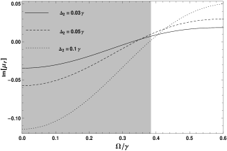
In the following,with the stationary solutions to the density-matrix equations(2)-(6), we explore the sign property of both electric permittivity and magnetic permeability through the numerical calculations. In what follows we choose the parameters for the QDs system, =2.5 Cm and =7.0 CRef20 . We choose the density of atoms N to be , . For simplify,the other parameters are scaled by : , , . The Rabi frequency of the pulsed laser is . Figure 2 shows the calculated electric permittivity and magnetic permeability as a function of the tunneling rate with the pulsed laser coupling the levels and resonantly. And the detuning varis with three different values: , and .
![[Uncaptioned image]](https://cdn.awesomepapers.org/papers/eca6682a-0ee2-47df-8e40-eaf10707c2ca/x2.png)
![[Uncaptioned image]](https://cdn.awesomepapers.org/papers/eca6682a-0ee2-47df-8e40-eaf10707c2ca/x3.png)


For the parameters we choose, left-handed properties of the QDs system are obtained inside the shaded area of Figure 2. We notice that the bandwidth for left-handed properties decreases with the increasing of the detuning , which is displayed by the computed dependence of the real permeability on the tunneling rate . And with the largest bandwidth of about 6.3 MHz, with the narrowest bandwidth of about 5.5 MHz. The QDs system is passive medium for the permittivity because of its real and imaginary parts having opposite sign, and increasing active for the permeability which imaginary parts have minus sign and increasing value.
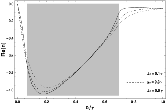
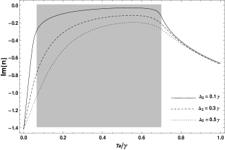
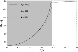
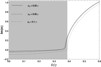
According to the refraction definition of the left-handed material , Figure 3 presents the computed dependence of the refraction index on the tunneling rate . In the shaded area, the real part of the refraction index shows the shrinking values and the imaginary part displays increasing gain response.
Above, the bias voltage manipulating the tunneling rate on the QDs system’s left-handed properties is taken into account. However, another one, the effect of pulsed laser should be included. Figure 4 depicts the dependence of the permittivity and permeability on the coupling intensity of the pulsed laser. And the tunneling rate , the detuning is varied by , , . The other parameters are the same to the former. The left-handed properties of the QDs system can be provided inside the shaded area varying the values of .
![[Uncaptioned image]](https://cdn.awesomepapers.org/papers/eca6682a-0ee2-47df-8e40-eaf10707c2ca/x8.png)
![[Uncaptioned image]](https://cdn.awesomepapers.org/papers/eca6682a-0ee2-47df-8e40-eaf10707c2ca/x9.png)
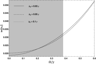
As observed in Figure 5, the real part of the refractive index shows negative values decreasing gradually with the increasing of . The imaginary part of the refractive index displays gain decreasing and near the transparency.
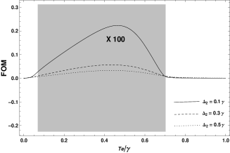
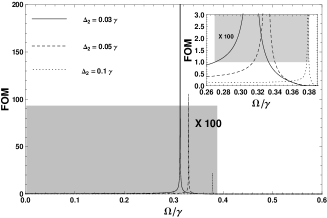
The figure of merit(FOM) Ref21 of negative index materials which has to be seriously considered since the low loss of negative refractive index materials is desired. When the FOM is much larger than unity, it means that there is almost little loss in this area. Via manipulating the bias voltage and the pulsed laser intensity, Figure 6 shows the figure of merit(FOM) the double QDs system in the shaded areas. We notice that the FOM is decreasing and far less than unity in the shaded area with different values when tunneled the tunneling rate via the bias voltage in the left of Figure 6. This illustrates that the QDs system displays left-handedness but the increasing loss when applying the bias voltage to tunnel the tunneling rate . However, varying the pulsed laser intensity the QDs system shows the different results. In the right one of Figure 6, the FOM has three peak and much larger than unity when varied by , and . The inset in the right shows the peaks of FOM present proximately at , and . It means that there is little loss for the QDs system when we applied the pulsed laser to the QDs system. The markedly feature of present scheme is the flexible manipulation on a solid state system to achieve the negative refractive index. We demonstrate left-handedness in the double QDs system applying the bias voltage and the pulsed laser.What’s more, when the changing pulsed laser is applied to the QDs system, the left-handedness with little loss can also be obtained.
IV The conclusions
In conclusion, we have demonstrated that left-handedness with negative refraction properties can be realized in a solid system, the double QDs system. It shows that negative refractive index with simultaneous negative permittivity and permeability can be achieved by tuning the tunneling rate between the double quantum dots via applying a bias voltage. Moreover, the negative refractive index with little loss can be obtained when the varying pulsed laser is applied to the double QDs system. This will be very helpful to the potential applications in optical devices designed. The varied tunneling rate via the bias voltage and the pulsed laser applied to the double QDs system give a more flexible manipulation on a solid system to realized negative refraction in the coming experimental research.
Acknowledgements
The work is supported by the National Natural Science Foundation of China (Grant Nos.61168001)and the Foundation for Personnel training projects of Yunnan Province,China (Grant No.KKSY201207068).
References
- (1) V.G.Veselago and E.E.Narimanov, Nature Mater., 5,(2006),759.
- (2) P.R.Berman, Phys. Rev. E 66,(2002),067603.
- (3) M.W.Feise, P.J.Bevelacqua and J.B.Schneider, Phys.Rev.B,66,(2002), 035113.
- (4) K.Aydin, I.Bulu and E.Ozbay, Appl. Phys. Lett 90,(2007)254102.
- (5) R.A.Shelby and D.R.Smith, Science, 77,(2001)292.
- (6) E.Cubukcu, Nature, 423,(2003),604.
- (7) J.Ktel, M.Fleischhauer, S.F.Yelin and P.L.Walsworth,Phys.Rev.Lett. 99,(2007), 073602.
- (8) M. . Oktel, . E. Mtecaplu, Phys. Rev. A,70,(2004),053806.
- (9) O.B. Shchekin, G. Park, D.L. Huffaker, and D.G. Deppe, Appl. Phys. Lett. , 77,(2000),466.
- (10) S.C. Zhao, Z.D. Liu, J. Zheng, G. Li, N. Liu,Optik ,123,(2012),1063.
- (11) A. Ekert and R. Jozsa, Rev. Mod. Phys., 68,(1996),733.
- (12) A. Imamolu, D.D. Awschalom, G. Burkard, D.P. DiVincenzo, D. Loss, M. Sherwin, and A. Small, Phys. Rev. Lett., 83,(1999),4204.
- (13) S.C.Zhao, Z.D.Liu and Q.X.Wu, J. Phys. B, 43 ,(2010),045505.
- (14) B.Krause and T.H.Metzger, Phys. Rev. B, 72,(2005),085339.
- (15) G.J.Beirne, C.Hermannstter, L.Wang, A.Rastelli, O.G.Schmidt and P.Michler, Phys. Rev. Lett., 96,(2006),137401.
- (16) R.Songmuang, S.Kiravittaya and O.G.Schmidt, Appl.Phys.Lett., 82,(2003,.2892 .
- (17) H.J.Krenner, M.Sabathil, E.C.Clark, A. Kress, D. Schuh, M. Bichler, G. Abstreiter, J.J. Finley, A. Zrenner, Phys. Rev. Lett., 94,(2005),057402.
- (18) H.J. Krenner, S. Stufler, M. Sabathil, E.C.Clark, P. Ester, M. Bichler, G. Abstreiter, J.J. Finley, A. Zrenner, New J.Phys.,7,(2005),184.
- (19) G.Bester, A.Zunger, J.Shumway, Phys. Rev. B, 71,(2005),075325.
- (20) J. M. Villas-Bs, A .O. Govorov and Sergio E. Ulloa, Phys. Rev. B, 69,(2004), 125342.
- (21) G. S. Agarwal, R.W.Boyd,Phys. Rev. A , 60,(1999),R2681.
- (22) J.Q.Shen,J. Mod. Opt., 53,(2006),2195-2205.
- (23) Q. Thommen, P. Mandel, Phys. Rev. Lett.96,(2006),053601.
- (24) J.Ktel and M. Fleischhauer, Phys. Rev. A , 79,(2009),063818.