\name: Efficient and Accurate Verification for Risk-Avoidance Routing in LEO Satellite Networks
Abstract
Emerging satellite Internet constellations such as SpaceX’s Starlink will deploy thousands of broadband satellites and construct Low-Earth Orbit (LEO) satellite networks (LSNs) in space, significantly expanding the boundaries of today’s terrestrial Internet. However, due to the unique global LEO dynamics, satellite routers will inevitably pass through uncontrolled areas, suffering from security threats. It should be important for satellite network operators (SNOs) to enable verifiable risk-avoidance routing to identify path anomalies. In this paper, we present \name, a novel network path verification framework tailored for emerging LSNs. \nameaddresses the limitations of existing crypto-based and delay-based verification approaches and accomplishes efficient and accurate path verification by: (i) adopting a dynamic relay selection mechanism deployed in SNO’s operation center to judiciously select verifiable relays for each communication pair over LSNs; and (ii) incorporating a lightweight path verification algorithm to dynamically verify each segment path split by distributed relays. We build an LSN simulator based on real constellation information and the results demonstrate that \namecan significantly improve the path verification accuracy and achieve lower router overhead compared with existing approaches.
Index Terms:
LEO Satellite Network, Path Verification.I Introduction
Low-Earth Orbit (LEO) Satellite Networks (LSNs) are gaining tremendous popularity in recent years, carrying a large fraction of Internet traffic [1]. Many “NewSpace” players like SpaceX [2] and Amazon Kuiper Project [3] are constructing their own LSNs powered by laser inter-satellite links (ISLs) [4, 5] to provide global Internet services. In particular, Starlink, the largest operational LSN today, has launched more than 6300 LEO satellites [6] and attracted more than 3 million global subscribers as of May 2024 [7]. As LSNs are developing at such a fast pace, security issues have become increasingly prominent. Potential threats in LSNs include not only traditional electromagnetic interference [8], but also new threats in cyberspace since LSNs target to provide global Internet services. Fundamentally, LSNs have a unique characteristic different from the terrestrial Internet: the core network infrastructures in an LSN (\eg a large number of satellite routers) are moving in their free-space orbits globally, and satellites will inevitably travel to uncontrolled and risky regions overseas. Such LEO dynamics can involve potential security risks such as traffic hijacking and information leakages [9] by hacking satellites [10, 11, 12]. Therefore, for satellite network operators (SNOs), it should be important to enforce the forwarding path to bypass potential risk areas and, more importantly, verify that the actual forwarding paths do avoid the risk areas. The network community has a very long history of working on path or routing verification. Depending on the verification criteria, previous approaches can be classified into two main categories: crypto-based and delay-based path verification. In the former, each intermediate node performs cryptographic operations on forwardings packets and appends a Message Authentication Code (MAC) to each packet [13, 14, 15]. Hence, the path can be verified by checking a chain consisting of nested MACs. However, such complex cryptographic operations incur substantial computation and bandwidth overheads on resource-constrained satellite routers. To avoid high router overhead, other efforts have proposed lightweight delay-based approaches to verify the network paths by comparing the estimated delay of the planned path with the real delay of the actual path [16, 17, 18]. In delay-based approaches, the network operator typically has to pre-deploy a set of relay nodes in advance, which are geographically very far away from the risk area. The path from a source to its destination is forced to pass through a certain relay. The underlying verification principle is that: due to the long distance between the relay and the risk area, if the actual path detours and passes through the risk area, the end-to-end path delay should be significantly higher than the estimated value. Note that this approach estimates the path delay based on a fundamental assumption in today’s terrestrial Internet that the propagation delay between two network nodes can be approximately estimated by a linear function of the physical distance between them [19]. However, in emerging LSNs, due to the unique global LEO dynamics, the entire network topology and paths fluctuate frequently [20, 21], causing the linear assumption does not hold anymore. As a result, existing delay-based methods suffer from poor accuracy in LSNs. To overcome the inefficiency and inaccuracy of existing verification approaches, in this paper, we present \name, a novel verification framework that extends existing efforts and accomplishes efficient and accurate network path verification in dynamic LSNs, by exploiting the following two techniques. First, \nameincorporates a dynamic relay selection algorithm together with a flexible relay-based traffic steering mechanism for SNOs to dynamically schedule LSN traffic to bypass risk areas. Unlike previous approaches that depend on static relays which may result in high verification errors, \nameproposes the Nearest Low-Risk Planes () to limit the risk nodes in a small range, and dynamically selects relays based on . As such, \nameeffectively avoids the risk areas without involving too much delay caused by risk-bypassing meandering routes. Second, \nameadopts a lightweight avoidance verification algorithm that integrates the routing information and propagation delays to jointly verify the path compliance between the planned and the actual paths. \nameverifies the entire network path by verifying all segments divided by relays. Specifically, in \name, only relays perform MAC operations to authenticate that the packets indeed pass through them and conduct delay-based verification for each segment path. Instead of using the linear RTT estimation like [16, 17, 18], \namefirst adopts an inter-relay probing mechanism to obtain each segment delay ground truth for a period. Then \nameestimates the segment detour delay threshold that functions as a jitter buffer by computing twice the minimum propagation delay from each node on the segment to the risk nodes based on the predictable satellite trajectory and topology [22]. The sum of them is the segment delay upper bound for determining if packets have traversed the risk area in this segment path. To evaluate the effectiveness of \name, we conduct a large-scale simulation by combining real-world LSN information [2, 3] and the recent LSN simulator [23]. Extensive experiments demonstrate that \namecan accomplish: (i) high verification accuracy: \nameobtains near-to- verification accuracy for city pairs served by Starlink and Kuiper constellations; (ii) low delay penalty caused by detours: compared with Alibi Routing [16], \namecan largely reduce the delay of verifiable risk-avoidance paths; and (iii) better scalability and performance: \nameachieves low processing overhead and can scale to LSNs with thousands of nodes, and \name’s achievable goodput ratio is much higher than existing crypto-based approaches [13, 14, 15]. In summary, the main contributions of this paper include:
-
•
We highlight the importance of path verification in emerging LSNs, and expose the inefficiency and inaccuracy problems of existing path verification approaches in LSNs (§II).
- •
-
•
We build a \nameprototype and conduct extensive simulations to demonstrate the effectiveness of \name, in terms of improved verification accuracy, performance, and reduced router overheads (§VI).
II Threat Model and motivation
II-A Preliminaries for low-Earth orbit satellite networks
Today’s LSNs like SpaceX’s Starlink [2] consist of hundreds to thousands of LEO satellites that work as “routers in space”, together with many geo-distributed ground stations connecting satellites and terrestrial network infrastructures. Satellites communicate with ground entities (\eg ground stations or satellite terminals) via ground-satellite radio links (GSL). Besides, many satellite constellations (\eg Starlink and Kuiper) leverage high-speed laser inter-satellite links (ISLs) for inter-satellite networking and communication. As visualized in [24], because satellites move at a high velocity in various orbital directions over the Earth, the entire LSN experiences frequent topology changes, especially in space-ground connections. LSN traffic between two terrestrial nodes (\eg from a Starlink’s satellite terminal to a remote ground station) is forwarded by a network path constructed by uplink/downlink and ISLs. To deal with the unique LSN topology fluctuation, many recent works have proposed space routing mechanisms (\eg [20, 21]) to dynamically build and maintain paths for any two terrestrial nodes connected to the LSN.
II-B Potential risks in uncontrolled areas
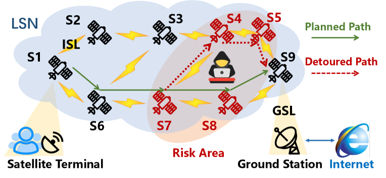
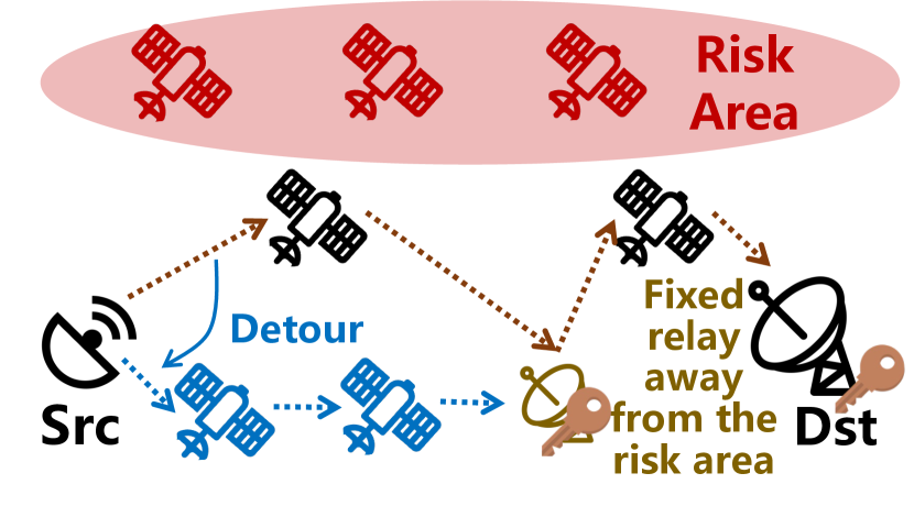
As plotted in Fig. 1, because satellites move globally, they might enter an uncontrolled risk area, posing routing security threats in LSNs. In this paper, we define a “risk area” as a geographical region where malicious attackers may exist there and launch the following attacks on satellites above the area:
-
•
Information stealing. Attackers in the risk area can eavesdrop on traffic and extract or speculate private data [9]. As shown in Fig. 1, assume traffic from the satellite terminal is expected to be forwarded to the ground station by a planned network path marked by the solid arrows, attackers in risk areas can eavesdrop on traffic forwarded from S7 to S9.
-
•
Traffic hijacking. More powerful attackers in a risk area can hijack [10, 11, 12] the route and cause path inconsistency. They propagate error routing advertisements to allure surrounding satellites to forward packets to them and redirect traffic to specific nodes for censorships, or other man-in-the-middle attacks like packet injection, modification, and counterfeit. In the example illustrated in Fig. 1, the attacker in the risk area may modify the planned path to S7S4S5S9.
Therefore, to avoid the above risks, it should be essential for satellite network operators (SNOs) to: (i) apply avoidance policies to force their traffic to bypass potential risk areas, and more importantly, (ii) verify that the actual paths are consistent to the planned avoidance policies in practice.
II-C Are existing path verification methods sufficient?
Over the past decade, the network community has had a body of efforts working on network path verification. In particular, existing path verification efforts can be classified into two main categories: crypto-based and delay-based approaches. Crypto-based path verification. One classic path verification approach is to embed the planned path (\eg a sequence of nodes that build the network path) into the header of each packet. Then intermediate nodes authenticate and update related fields before sending to the next node [13, 14, 15]. These approaches have three limitations in LSNs. First, each intermediate node needs to perform cryptographic operations like calculating MACs hop by hop, which involves high computation overhead that could be unaffordable for resource-constrained satellites. Second, the increased length of the verification header also leads to extra packet header overhead, resulting in goodput ratio reduction (as will be analyzed in detail in §VI). Third, per-hop authentication inevitably involves additional processing delay on each node. Note that the high mobility of LEO satellites incurs frequent path changes [25, 22, 20], if the packet processing delay is too high, the pre-calculated path might be invalid on the route. Although some recent works like PPV [26] and MASK [27] propose probabilistic authentication instead of verifying every packet hop by hop, the computation overhead can be still high when the traffic volume is large. Delay-based path verification. Alibi Routing [16] proposes a new path verification approach, exploiting the key idea that a detour from the planned path to any node in the risk area will breach the maintained delay by incurring significant extra delay. To verify whether a network path from a source () to its destination () passes through the risk area, Alibi Routing pre-computes a target area that is far away from the risk area where possible verifiable relays (called alibis) are located. It enforces that the path from to must pass through the alibis. Because the relay is very far from the risk area, if the path passes through the risk area, the observed end-to-end delay should be significantly higher than the maintained value. However, these approaches are based on a fundamental assumption that the delay between two terrestrial nodes has a linear relationship with their great-circle distance. Although this assumption exists in many scenarios in today’s terrestrial Internet [19], it is not applicable in LSNs with highly dynamic topology. An increase in path delay may not necessarily be caused by traversing the risk area but path changes due to topology fluctuation. We conduct a quantitative analysis to demonstrate how the unique topology fluctuations in LSNs affect the verification accuracy of existing delay-based approaches. Our analysis is based on the real Starlink constellation information [2] and an LSN simulation based on StarryNet [23] (details will be illustrated in §VI). We build a virtual LSN consisting of 1584 satellites with 72 orbits and 22 satellites per orbit (Starlink Phase 1, Shell 1) and 165 geo-distributed ground stations [28] around the world. We simulate about 2000 city pairs communicating over the LSN and use the shortest path routing upon the +Grid topology, \ie a satellite connects two neighboring satellites in the same orbit and two in the adjacent orbits [20].
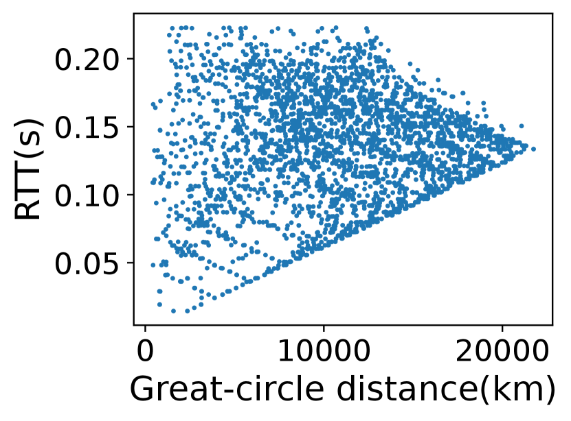
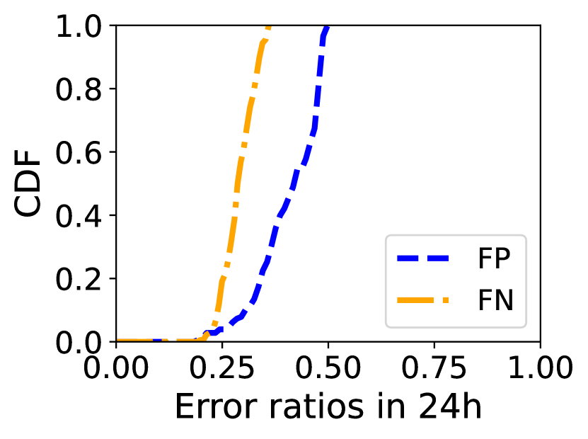
First, we observe that the linear relationship assumption [19] does not hold in LSNs as illustrated in Fig.3. On our further investigation, we confirm that the delay increase is caused by frequent topology fluctuations and path changes in LSNs even if the and are static on the ground. Second, we observe the non-linear relationship can lead to inaccuracy for delay-based verification approaches. We simulate the Alibi Routing [16] mechanism, set Egypt as a potential risk area, and set a static ground relay for each city pair. We calculate the ratio of false positive (FP, \ie the real path does not traverse the risk area but is considered as passing through it) and false negative (FN, \ie the opposite of FP) of each city pair in 24 hours with an interval of 1 second. These error ratios are defined as the proportion of the amount of time slots that FP or FN occurs to the total amount of time slots. Fig. 3 plots the CDF of the error ratios of the city pairs. We observe that delay-based verification methods suffer from high inaccuracy since most city pairs’ FN and FP ratios are higher than 25%. Our motivation. Accomplishing path verification is important in dynamic and uncontrolled LSN environments. However, existing methods suffer from either per-node high processing overheads, or verification inaccuracy, which motivates us to explore a more efficient and accurate solution for network path verification in LSNs, \ie the \nameframework.
III \nameOverview
III-A \namearchitecture
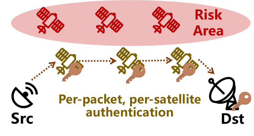
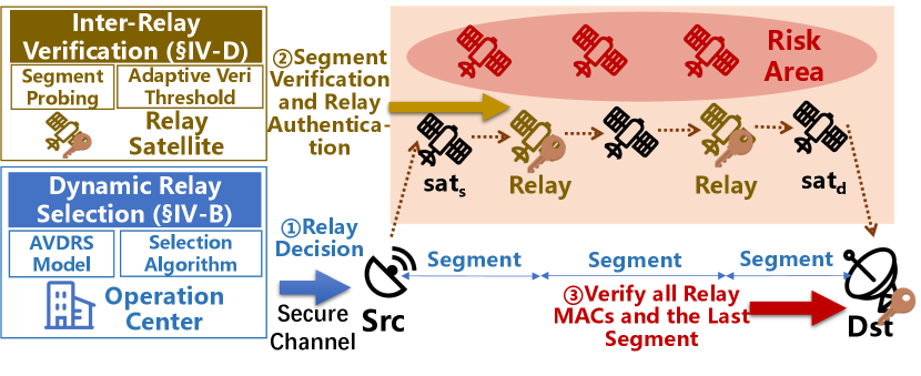
Basic idea. At a high level, \nameaddresses the limitations of existing approaches in terms of overhead and accuracy as follows. First, to verify a network path from to , \nameadopts a collection of dynamic satellite relays to split the entire path into a series of consecutive segments. Thus, verifying the entire path is equivalent to verifying each segment path. Second, to reduce the verification overhead, \nameonly requires relays (instead of all nodes on the path) to authenticate forwarded packets. Therefore, it can be verified that the forwarding path indeed passes through the predefined relays by checking the relay’s authentication chain in . Third, while the end-to-end delay of a network path fluctuates due to the LSN’s dynamics, the delay fluctuation of a segment (\eg between two adjacent relays) is less dramatic than the delay fluctuation of the entire path. \nameverifies each segment by comparing the real inter-relay delay with the estimated upper bound. Architecture. Fig. 4 plots \name’s high-level architecture and an illustration of the key differences between \nameand existing verification approaches. \nameprovides the SNO with the ability to verify the path compliance between the planned packet delivery path and the real one. \namecan be built upon existing Path-Aware Networking (PAN) [29, 30] architecture that allows end users to self-define paths for packets, or source routing [31], both enforcing network paths to pass through pre-calculated satellite relays. In addition, \nameincorporates two new features for dynamic LSN path verification. First, \nameadopts a Dynamic Relay Selection mechanism deployed in SNO’s operation center to judiciously select relays for every communication pair over the LSN. These relays then split the entire path from to into a sequence of consecutive segments. Second, \nameincorporates a probing mechanism to periodically obtain the segment delay between any two adjacent key nodes (, relays, and ) and an Inter-Relay Verification approach deployed on selected satellite relays and to verify whether the segment path is consistent with the planned path. If the packet on the current segment path does not traverse the risk area, the relay node will perform a symmetric MAC to update the passing packet’s authentication fields.
III-B \nameverification workflow
For each communication pair (, ) and a given risk area, \nameaccomplishes the verification as follows. (1) Dynamic relay selection. \namefirst calculates a time-varying relay set which includes all relays for (, ) at different time slots. Then it estimates the segment detour delay threshold which is used to calculate the segment delay upper bound based on the relay sequence. All the information is computed based on the predictable satellite trajectory and dynamic LSN topology. Once decided, the SNO operation center delivers the results to . (2) Intra-segment state probing. If a path changes or a new session begins, end users, relays and SNO negotiate session keys [14] which is out of our scope in secure channels [32]. After that, each relay (including ) periodically (\eg tens of seconds) sends a probing packet to its previous relay to probe delay of the current segment. To ensure that probing packets are not tampered with, all nodes on a segment path authenticate the probing packet with adjacent shared symmetric keys [16]. (3) Authentication fields initiation. Before a packet’s departure, inserts the corrected sending timestamp, hash value, and relay authentication fields in the packet header. (4) Relay-based segment verification. Network nodes forward the packets according to the planned path. When a relay receives packets, it verifies the segment path based on its probing ground truth and detour threshold. If packets do not traverse the risk area, the relay computes a MAC value and inserts it with the timestamp to update its part in field. (5) Destination verification. After receiving a packet, verifies the packet’s source (out of our scope), fields updated by relays, and the last segment path to determine whether the packet bypasses the risk area.
III-C Technical challenges
To accomplish efficient and accurate verification, \nameneeds to solve the following LSN-specific challenges. Appropriate relay selection under LEO dynamics. Considering the high dynamics in LSNs, correctly and timely selecting verifiable relays away from the risk area while not involving too much additional delay at a global scale is challenging. Specifically, we formulate the Avoidance-Verifiable Dynamic Relay Selection (AVDRS) problem in LSNs, based on which we further design an efficient solution. Unpredictable delay jitters. Only exploiting the period probing delay ground truth as an upper bound to verify whether a packet has gone through the risk area is too strict. It’s impossible that the real delays are equal to the probing delays exactly. It’s hard to distinguish whether an observed micro delay increase is caused by slight delay jitters or detours which may mislead the segment delay-based verification. In the next section, we introduce the details of \nameand describe how \nameaddresses these challenges.
IV \nameDesign Details
IV-A Modeling an LSN
Network model. To model the LEO dynamics, we divide time intervals into discrete time snapshots . During , the LSN topology and distance between neighboring satellites are nearly constant. The topology at is represented by a graph ( is the union set of satellites , and ground entities ). is the link set of ISLs and GSLs. If node are connected at , the variable . The orbit can be represented by a number (, where is the amount of orbits). Similarly, we use (, where is the number of satellites per orbit) to describe the in-orbit position of a satellite. Formally, a satellite can be represented by a unique logical coordinate . Link establishment and path construction. At time , the SNO will compute the risk satellites, \ie in the risk area . We set as the path at between nodes consisting of a sequence of on-path nodes. The segment path between adjacent nodes in is the shortest routing path computed by Dijkstra ( is the satellite relay set, ). As the chosen relays are in order, we use a sequence set to describe the relation in a path, and means node precedes node . The active link between adjacent nodes is . The delay between any two neighboring nodes can be estimated by dividing their straight-line distance by the light speed. is the total delay of . Since there exist several paths between two nodes with similar delays, we use a set to contain all the related nodes in these paths.
IV-B Dynamic relay selection
AVDRS Formulation
considering LSN topology’s frequent variation, to ease the burden brought by global users’ frequent requests, SNO should reduce communication frequency by pre-computing results during a future period for satellite terminals (\eg dish) to store them. It’s vital to ensure a short end-to-end delay, which limits us from selecting remote relays. We formulate the Avoidance-Verifiable Dynamic Relay Selection (AVDRS) problem which aims at selecting viable satellite relays while satisfying low delay inflation. Input: the topology , access satellite pairs , of and respectively, and the risk satellites . Output: the selected relay sequence . Goals: \nametargets at obtaining the relays while minimizing the end-to-end delay between to at :
| (1) |
Constraints: Constraint 2 describes the node sequence of a path. is the distance between an on-path node and a risk satellite and it limits the candidate relays’ range. The larger the is, the further the relay is, and it’s more secure while incurring longer end-to-end delay. Constraint 4 depicts the connectivity of the constructed path. Constraint 5 ensures no equal paths can traverse . Every relay needs to authenticate the packet and the related field length increases as its number grows. So the last constraint limits the number of chosen relays to lower the communication overhead. Intuitively, more relays mean finer verification granularity, \eg all the on-path nodes authenticate. However, from our analysis, a bad relay may incur a longer delay and not contribute to the verification accuracy.
| (2) |
| (3) |
| (4) |
| (5) |
| (6) |
Problem analysis. To solve the problem above, SNO should calculate the optimal solution in each time slot for large amounts of users. Since the available relay amount for LSNs is , the combination number is ) at a time (the sequence is in order), which cannot be calculated in a short time, let alone for millions of global users. Besides, to satisfy Constraints 2 and 5, the problem is more complex as it can be analogized to NP-hard Hamiltonian Path Problem (HPP) [33].
Corollary 1
AVDRS problem can be analogized to HPP.
Proof 1
HPP specifies a set of points and finds a path in the graph that visits every point only once. We set an unordered and a graph where if the closed , then . The problem is reduced to finding a sequence that can traverse every relay only once.
Dynamic Relay Selection Algorithm (DRSA)
The details of DRSA are shown in Alg.1. DRSA limits within a range to ensure that as many close low-risk satellites outside the range as possible can be candidate relays.
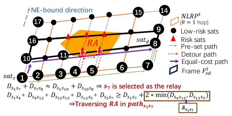
Calculating the Nearest Low-Risk Planes (NLRP). consists of eight low-risk planes, \ie four planes in each orbital direction. NE-bound direction is that satellites fly from Southwest to Northeast, and SE-bound is from Northwest to Southeast [24]. limits the risk satellites in a range (it is adjusted by in Constraint 3, which helps set delay buffers against unpredictable delays according to current network conditions. If is defined as the number of hops, is -hop away from the outermost edge risk satellites). Then the upmost, bottommost, leftmost, and rightmost low-risk planes in two orbital directions respectively can be obtained
| (7) |
where, represent the left, right, up, and bottom, and means the orbital direction (Fig.5 only shows NE-bound and SE-bound is a closed frame in different direction interwoven with NE-bound ). Dynamic Relay Selection Algorithm (DRSA). Then DRSA selects relays as shown in Alg.1. We discuss it in two cases: and , where is the satellite direction. When , firstly a frame formed by the planes of and is obtained as seen in Fig. 5. Next, DRSA sets in which a relay is located in the same plane of the previous and the following nodes in to make sure there are no other equal-delay segment paths theoretically. Setting relays in this way can reduce the risk that other paths with similar delays traversing affect the verification accuracy. If and do not overlap (Line 3-4 in Alg.1), \eg formed by and in Fig. 5, all the nodes constructing possible equal-cost shortest paths from to are contained in . In this case, is the only relay since it’s farther away from . Otherwise, there are two types of overlap: semi-overlap seen in Line 5-7, (\eg in Fig. 5) and fully-overlap seen in Line 8-11, (\eg in Fig. 5). In semi-overlap, there exists a candidate path that does not traverse while achieving the shortest delay and DRSA selects this corner node as the only relay, \ie the equal-cost path depicted by the thicker purple solid arrows traverses , so is the relay and the shortest path is the path depicted by the finer green solid arrows. In the second case where all the candidate paths contain risk satellites, DRSA enlarges the and selects the corner nodes that are located on the intersection of a certain border of and the planes of , as relays, \ie .
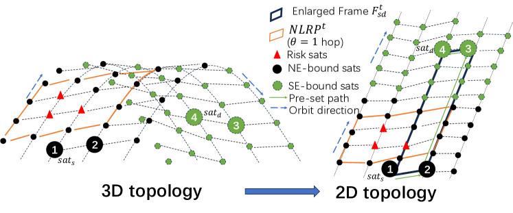
If , it can also use the same-direction way above. As shown in Fig. 6, we approximately convert 3-D into 2-D topology and determine the intersection relationship between and . For example, Fig. 6 plots the topology transformation and the chosen relays which are the corner nodes in this case. Setting detour threshold. As mentioned in §III-A, \namedivides a path into several segments and each relay or authenticates one segment. The real delays vary dynamically, nearly fluctuating within a certain range. As each segment path is the shortest path, we assume no attacks will incur a lower delay than the probing delay during a period, so what is the delay upper bound for a packet to be considered as not traversing ? If an on-path node mis-forwards the packet to , the minimum detour delay is more than twice the minimum propagation delay between any on-path node and any risk satellite like in Fig. 5. Therefore, SNO sets a segment detour delay threshold between any two adjacent nodes constructing a segment as:
| (8) | |||
Discussion of number of relays . Taking in Fig. 5 as an example: (i) if we select a bad relay sequence like , not only is path longer but the relay is closer to the risk satellite , increasing verification inaccuracy; (ii) if we set as the only relay, the verification granularity seems finer as the path is divided into and . But the gain is trivial since the detour threshold in such two segment paths is similar, \ie . Particularly, no relay is needed if and are in the same plane and not in the fully-overlap case (\eg and are in the same plane). To sum up, DRSA minimizes to a large extent by constructing and setting at most two relays.
IV-C Pre-process at
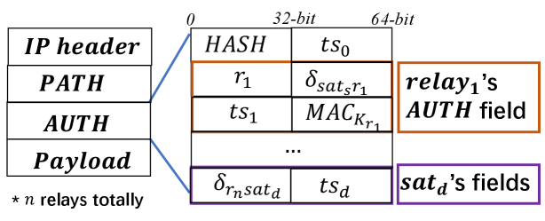
Before communication begins, and SNO exchange Veri infos including the detour threshold list , and relays during a future period. Every time a connection begins or relays change (inspected by querying its local cache in each time slot), , , and relays negotiate session keys and achieve the path authorization [14] (out of our scope) through secure channels between them and SNO [32]. Then, when sending a packet, first sends a probe to test the current access delay to eliminate the error brought by the first hop. Next, records the corrected sending timestamp ( is processing time) and calculates the truncation of the hash value , where is the truncation of the lowest B of the data to improve goodput [15, 27]. Then constructs the reserved chain, makes a final packet source authorization and sends . Each relay’s field is shown in Fig. 7 where , including relay’s ID , segment detour threshold , timestamp when sending out the packet, and its MAC authentication value.
IV-D Relay-based segment verification
When receiving a packet, the satellite should determine if it is a relay by checking the chain. If not, it just forwards it without doing any operations. Otherwise, after negotiating the session keys and obtaining the segment path and relay sequence, periodically, the relay probes with a nonce to its previous relay for some link states like queuing and processing delay. The probing reply packets must have been authenticated hop by hop on this segment path through the neighboring shared symmetric keys [16, 26]. Then, the relay obtains the probing delay of the segment path. Similarly, announces the last segment delay to . Next, upon receiving normal communication packets, the relay just checks if its previous relay has updated but ignores its validation as \nameoffloads the step to . Then, it determines whether the real delay of this segment path has exceeded the upper bound, \ie
| (9) |
If not, it calculates and inserts it into the packet together with and sends the packet. If all the intermediate relays have updated the related fields and the packet is forwarded to , inserts the time when it receives the packet and forwards to .
IV-E Final path verification at
When receives the packet, it verifies the packet in the following steps: (i) it first authenticates the packet’s source validation (this is out of our scope); (ii) after that, it calculates the hash value in the same way as to verify if the packet has been tampered; (iii) then it authenticates the MAC chain of relays by re-computing MACs with their shared session keys to verify that the real path has indeed gone through these relays and passed all these relay’s verifications; (iv) lastly, authenticates the last segment path in the same way as relay‘s. If all the four conditions are satisfied, accepts it and considers it not traversing the .
V Security Analysis
Defense against hijacking. When benign nodes outside mis-forward packets into and the packets are redirected to other colluded evil nodes without modifications, the packets are ultimately forwarded to at least a benign node, \eg . This node will forward them to the next node according to the pre-set . Any path inconsistency will incur an extra delay that exceeds the pre-set segment delay upper bounds. Defense against path counterfeit and modification. Some evil nodes may collude with each other by modifying the sequence or the next relay when the packets have entered the . In the former attack, although the real path is different, will detect it by authenticating the source and recomputing the packet’s of the planned path; while in the latter case, a packet may skip some nodes. If skipping some normal nodes on a segment path, the segment delay will be prolonged as mentioned above; and if skipping relays, the downstream relays or will drop the packet as the previous one does not update its field. If some colluded satellites forge timestamps and MACs, will detect it by re-computing the real relay’s MAC chain. Defense against replay. The value contains the timestamp when sending the packet to ensure freshness. Adversaries do not know the session keys, so they cannot forge the source of a packet. Besides, the expired packets will not pass the delay-based verification.
VI Performance Evaluation
Our evaluation in this section focuses on the following aspects related to \name: (i) Q1: can \nameachieve high accuracy for network path verification in dynamic LSNs? (ii) Q2: can \name’s verifiable risk-avoidance routing be exempt from severe delay penalty? (iii) Q3: does \nameinvolve acceptable overhead on satellite routers? and (iv) Q4: can \namescale to large-scale LSNs?
VI-A Experiment setup
Prototype and testbed setups. \nameprototype has two major components: (i) \name’s controller. \namecontroller is implemented on a simulation testbed based on StarryNet [23], a novel docker-based framework to simulate large-scaled LSNs written in Python. The controller reads the satellite location data produced by StarryNet first. Then it invokes the DRSA module to calculate the risk satellites and s based on the self-defined risk area. After that, the controller calculates the dynamic relays periodically, obtains the segment detour delay thresholds, and constructs the complete routing path for each communication city pair. (ii) Satellite routers and city pairs. They are simulated as individual containers with a complete TCP/IP stack on StarryNet to provide delay with processing time. Based on IPv6 which has an optional hop-by-hop header for every intermediate node to process packets, the verification-related data (seen in Fig. 7) are embedded in the hop-by-hop header. We use HMAC-SHA256 [34] to calculate the digest and extract its first 4 bytes. pings continuously. Each ping packet is processed in an individual queue by the module Netfilter [35]. As seen in Alg. 2, after obtaining the segment detour delay thresholds and path from the controller, pre-processes each ping packet by embedding them with timestamp, , and fields. The relays update the fields and forward the packets to which makes the final verification decision. The normal nodes forward the packet without extra operations. The whole simulation environment is built on two high-end servers equipped with Xeon(R) Gold 5215 CPUs (2.50GHz) and 512GB memory. Dataset and parameter setting. We choose 197 communication city pairs distributed mainly in America and part of South Asia within the service range of Starlink [36]. To measure the overheads and accuracy, we ping (longer than an orbital period) for some city pairs with different path lengths and numbers of relays simultaneously on StarryNet. In \name, we set three cases of that measure the distance from the to the risk satellites in Constraint 3. We apply Alibi’s relay selection methodology for LSNs (which is also used in §II-C) and select ground stations as relays. Alibi has a similar user-configurable variable to find relays. A larger means fewer relays can be found since the target area where relays are located is smaller, but it’s better to resist delay jitters incurred by congestion, \etc We set 2 different-sized countries as risk areas: Egypt and North Korea. Constellation parameters. Our LSN simulation is based on real-world LEO constellation parameters. Specifically, in addition to the constellation and basic network setups in §II-C, we also simulate Amazon Kuiper with 1156 satellites evenly distributed in 34 orbital planes [3].
VI-B Verification accuracy
We set a traffic hijacking scene where packets are forwarded to the risk nodes to see if the prolonged detour delay can be detected. After running our experiments on StarryNet for several hours, \name’s verification accuracy reaches in the cases of different numbers of relays. The real detour delay is larger than the pre-set upper bound, as such, no packet that enters the risk area is considered as not traversing the risk area. In the simulation testbed, Alibi produces and average FP and FN ratios when the risk area is Egypt. Such poor accuracy of Alibi results from frequent variation of the GSLs between satellites and static relays.
VI-C Network performance
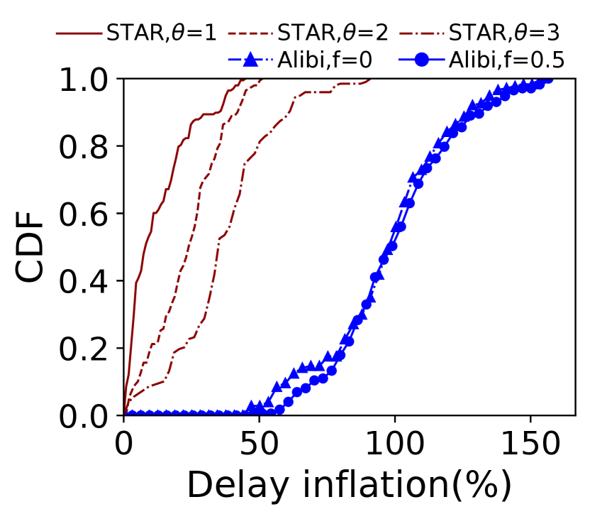
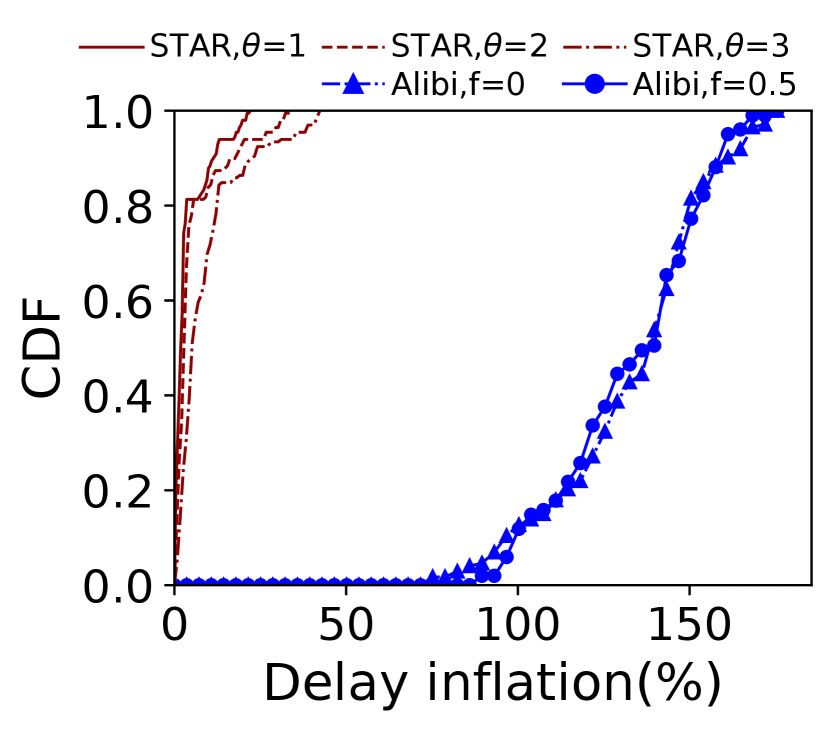
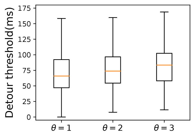
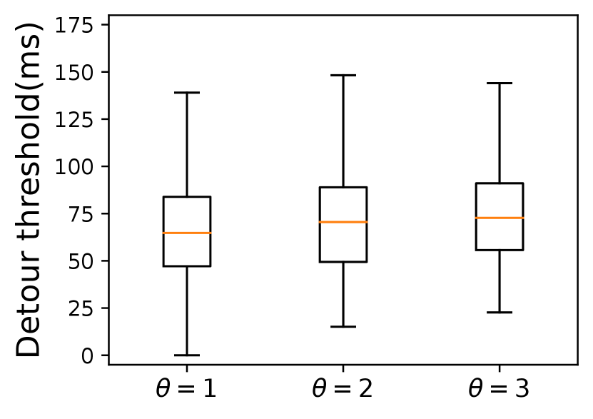
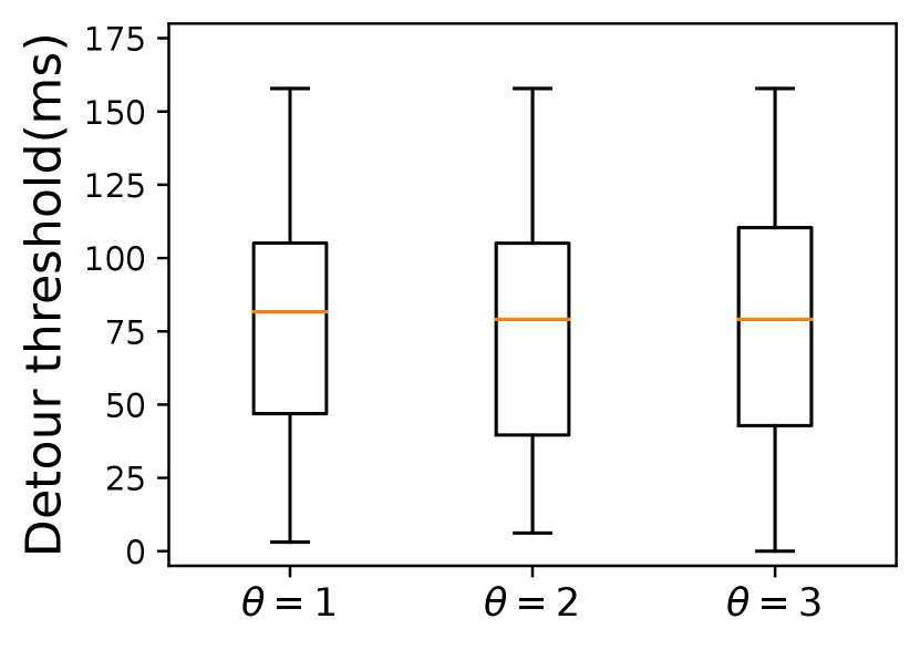
Selecting relays far away from the risk area ensures better verification accuracy but incurs larger delay inflation. So we set a configurable variable in Constraint 3 that depicts the size of (\ie the distance between the borders and the marginal risk satellites) to make a trade-off between verification accuracy and end-to-end delay. As shown in Fig. 8, a larger does incur a longer end-to-end delay, which holds true in both constellations as shown in Table I. However, from a global perspective, the average extra delay of \nameis within a reasonable range compared with Alibi. The maximum delay inflation of Alibi reaches and in two risk countries respectively when . Besides, limited by the small number and uneven distribution of ground relays, Alibi cannot always find verifiable relays. When is larger, there is a high possibility that no fixed relays will be found. From our analysis, only 112 of the 197 communication pairs can be assigned a fixed relay when the risk area is North Korea. However, \namecan choose global satellites as relays to verify a path only if the users’ access satellites are not located inside the . On top of that, Fig. 9 plots the detour delay thresholds under different s defined in Constraint 3. \nameachieves a delay buffer from tens to hundreds of milliseconds. This additional buffer against unpredictable delay jitters functions better when the is larger. When avoiding Egypt, the detour threshold increases as the increases. However, there is no explicit detour threshold increase when avoiding North Korea. For example, the average detour thresholds of the three cases of different s in Starlink are all about 75ms, which means when the risk area is small, setting a smaller may be enough to achieve a high verification accuracy.
| Starlink | Kuiper | |||
|---|---|---|---|---|
| Egypt | North Korea | Egypt | North Korea | |
VI-D Verification overheads
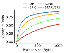
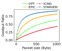
We analyze the overheads in two aspects: communication overhead and computation overhead and compare \namewith three crypto-based approaches ICING [13], OPT [14], and EPIC [15]. The verification header length of the three methods increases as the path length grows because they verify the path hop by hop. Communication overhead. Our \namefield length is at most no matter how many hops a route has as there are two relays at most (one relay consumes fields) as shown in Table II. To compare them in a meaningful way, we use a IPv6 header plus the security-related fields. As shown in Fig. 10, the longer the path is, the more communication overhead the hop-by-hop methods incur especially ICING. Since the constellation scale is much larger than a single AS in the terrestrial network, it’s normal to transmit traffic on a path with tens of hops in LSNs. Fig. 10 plots the theoretically maximum goodput ratios (GR) under different hops. \nameachieves 110.16%, 43.53%, and 11.33% higher GRs than ICING, OPT, and EPIC respectively in the case of 30 hops, 1024B payload, and the number of relays .
| Path Len | ICING[13] | OPT[14] | EPIC[15] | \name |
|---|---|---|---|---|
| 16/32/48 | ||||
| 16/32/48 | ||||
| 16/32/48 | ||||
| 16/32/48 |
| \name | EPIC | |
|---|---|---|
| 172 | 6241 | |
| 308 | 5820 | |
| 550 | 6062 |
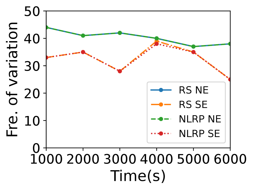
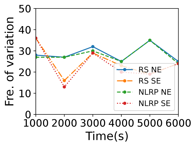
Computational overhead. The complexity of computing relays and detour thresholds is and there is no need to calculate them frequently. If none of , and changes, the relays will change neither. Here we discuss the variation frequency of . Fig. 11 plots the variation frequency of and the risk satellites every 1000s when the risk area is Egypt. In Starlink, the average variation interval of ’s up and bottom planes is about 260.70s. Generally, the variation frequency of is fewer than that of . The satellite distribution in Kuiper is sparser, so even if changes, the may not change. So \namelargely decreases relay selection and key negotiation frequency.
Besides, \nameis not a hop-by-hop verification method, incurring only a little verification delay caused by at most two cryptographic operations. We compare \nameto EPIC which also has one MAC operation per hop. As shown in Table III, \name’s verification delay is 97.2% less than EPIC when the path has 35 hops.
VI-E Scalability analysis
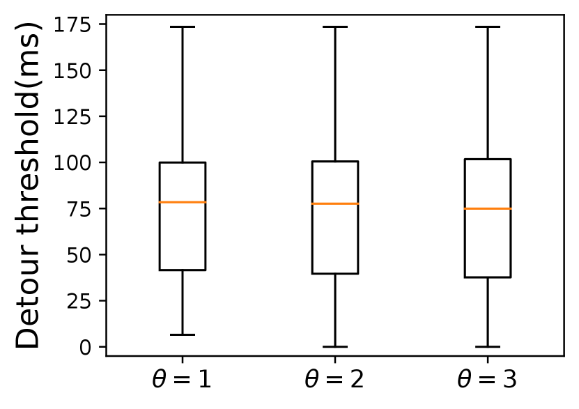
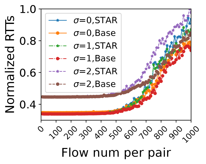
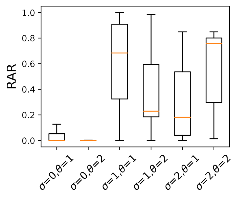
We analyze the RTTs when a path loads different numbers of flows in parallel obtained from StarryNet as shown in Fig. 13. When the number of flows is small, \namenearly incurs no verification delays. As the number of flows grows, \nameincurs more verification delay, especially when . The average verification delay of processing between 700 and 1000 flows in parallel is 86ms, 92ms, and 134ms in three s respectively. Hence, SNOs should consider setting a larger when the number of flows is large. Next, we analyze the number of required relays. If the number is small, the key negotiation overhead is low. \namewill choose a certain number of relays for a communication pair at a certain time. The proportion of these time slots when selecting relays is . For example, \nameselects a relay for a pair for 600s during the past 1000s, so . Fig. 13 plots the boxplot of s of 197 global pairs in Starlink when avoiding Egypt. The average of all these pairs when is only 29.6%.
VII Discussion
Probing period. If the probing period is too short, more probing packets are needed; and if it’s too long, the previously measured delay ground truth may not work if the path has changed. Based on our simulations, we quantify the path variation frequency. We set the access strategy that the end users connect to the nearest satellites. The results show that when the risk area is Egypt and , the paths vary every 26.2s and 26.7s on average in Starlink and Kuiper respectively during the 6000s. The maximum variation interval is 124s and 148s respectively. Normally, a path variation occurs when either of the following cases occurs: i) the access satellites of the end-users vary, or ii) the risk satellites vary. In addition, the path frequency varies with different-sized risk areas. In the future, we will further quantify the modest probing period considering the path variation. Real-world deployment. Since an SNO controls an individual satellite network, the related verification protocols and standards can be deployed in its satellites, and there are encrypted tunnels among the end terminals (\eg dish), satellites, and ground stations [32] to transmit secret authentication information. \namecan be deployed on the Path-Aware Internet Architecture [30, 37, 38, 31] where endpoints can customize paths for given destinations, flows, or packets. After the packets are sent out, satellites follow the forwarding paths embedded in the packets. Avoidance of multiple risk areas. Multiple risk areas may be set by the SNO simultaneously and \namestill works by deciding the intersection relations between the frame constructed by the access satellites and the of each risk area. The SNO can set some middle waypoints between adjacent risk areas. Thus the packets are forwarded to these waypoints in order. Each adjacent waypoint pair (including access satellites) is like an individual city pair’s access satellites and the path between them avoids a single risk area. Besides, if these risk areas are close, SNO can aggregate their s as a larger one and then follow the way of \name. So it’s possible to have only 2 relays when avoiding two risk areas located closely but the aggregated will be larger. In future work, we will apply \nameto the cases where end users are in the s.
VIII Related Works
We briefly discuss other related works uncovered by §II-C. Path-Aware Networking (PAN). PAN architecture proposes a way for end-users to self-define the paths in data planes flexibly [30, 37]. All these works provide a basis for the source to insert a path into the packet to guide the intermediate nodes to forward it. LSN routing. There are few routing methods aimed at avoiding risk areas in LSNs, so we roughly introduce some routing methods that can be modified to apply in avoiding risk areas. In some solutions [20, 39], the source calculates a low-risk path by utilizing the topology that eliminates risk nodes in advance and inserts it into the header of each packet. Location-based routing [21] proposes a distributed geographical routing method that utilizes the information of ground cells and relative locations to decide which is the next hop. LRAR [40] is the only routing method for avoiding risk areas. Though these ways can be used to avoid risk areas, it’s hard to prove the real avoidance. Traffic engineering in LSNs. Some traffic engineering methods [41, 42, 43] can transfer the risk nodes into faulty nodes and consider them unreachable. As such, they predict the failure and back up all routing tables in advance. But it brings a lot of storage burden to satellites. StarCure [44] turns the failure nodes (risk nodes) into congested ones and schedules traffic onto other available routes. But it also lacks the ability to verify that the paths avoid traversing the risk area.
IX Conclusion
Dynamic LEO satellites may enter the risk areas and suffer from security issues like hijacking and information stealing in LSNs. To prove that the real route does avoid the risk areas, a path verification method should be proposed in LSNs. However, existing path verification methods can not adapt to the highly dynamic LSNs for their high communication or computation overheads in crypto-based ways, and low accuracy in delay-based ways. Therefore, we propose the lightweight \namethat integrates the advantages of both methods and utilizes satellite trajectories, routing information, and propagation delays to verify that the real path does avoid the risk area. Our extensive simulation proves that \namecan achieve near 100% accuracy. Besides, compared with those hop-by-hop methods, \namelargely reduces overheads and has great scalability.
X Acknowledgements
We thank our shepherd Olaf Maennel and the anonymous ICNP reviewers for their comments and suggestions. This work is supported by the National Key R&D Program of China (No. 2022YFB3105203) and the National Natural Science Foundation of China (NSFC No.62372259).
References
- [1] N. NEWS, “Traffic from elon musk’s starlink satellites tripled this year, says new report,” https://www.nbcnews.com/tech/innovation/elon-musk-starlink-satellite-traffic-brazil-us-ukraine-gaza-rcna129100, 2023.
- [2] SpaceX, “Starlink constellation,” https://www.starlink.com/, 2024.
- [3] Amazon, “Project kuiper.” https://www.aboutamazon.com/what-we-do/devices-services/project-kuiper, 2024.
- [4] “SpaceX FCC update. SPACEX NON-GEOSTATIONARY SATELLITE SYSTEM.” https://licensing.fcc.gov/myibfs/download.do?attachment_key=1569860, 2024.
- [5] “Kuiper Systems LLC. Application of Kuiper Systems LLC for Authority to Launch and Operate a Non-Geostationary Satellite Orbit System in Ka-band Frequencies.” https://licensing.fcc.gov/myibfs/download.do?attachment_key=1773885, 2024.
- [6] J. space page, “Starlink statistics,” https://planet4589.org/space/con/star/stats.html, 2024.
- [7] T. Mogg, “Spacex’s starlink internet service reaches milestone,” https://www.yahoo.com/tech/spacex-reaches-milestone-starlink-internet-032052994.html?guccounter=1&guce_referrer=aHR0cHM6Ly93d3cuZ29vZ2xlLmNvbS8&guce_referrer_sig=AQAAAMC55FtwTqRzd8xlcxcNuLrFirz7NqDFpidjs0vdCYKcFZVdSHyr9H8VSHJg0GHdOjgwOTNui5l2hW6HhDFHtVh8bDx4B1kq2hQ1BCE6WLU7gKSDYXWBwsSZFFwDgoHL2fkNrg1kt_vsscXOoCvjAoNPul3h72WbecsefO4nrexV, 2024.
- [8] E. Musk, https://twitter.com/elonmusk/status/1500026380704178178?ref_src=twsrc%5Etfw., 2022.
- [9] “Russian hackers hijack satellite to steal data from thousands of hacked computers,” https://thehackernews.com/2015/09/hacking-satellite.html, 2015.
- [10] D. R. Staff, “Russian satellite internet downed via attackers claiming ties to wagner group,” https://www.darkreading.com/cyberattacks-data-breaches/hackers-claiming-wagner-group-ties-down-russian-satellite-internet-comms-, 2023.
- [11] R. Lemos, “Space race: Defenses emerge as satellite-focused cyberattacks ramp up,” https://www.darkreading.com/ics-ot-security/space-race-defenses-satellite-cyberattacks, 2023.
- [12] I. Thomson, “Want to pwn a satellite? turns out it’s surprisingly easy,” https://www.theregister.com/2023/08/11/satellite_hacking_black_hat/, 2023.
- [13] J. Naous, M. Walfish, A. Nicolosi, D. Mazières, M. Miller, and A. Seehra, “Verifying and enforcing network paths with icing,” in Proceedings of the Seventh Conference on Emerging Networking EXperiments and Technologies, 2011.
- [14] T. H.-J. Kim, C. Basescu, L. Jia, S. B. Lee, Y.-C. Hu, and A. Perrig, “Lightweight source authentication and path validation,” in Proceedings of the 2014 ACM Conference on SIGCOMM, 2014, pp. 271–282.
- [15] M. Legner, T. Klenze, M. Wyss, C. Sprenger, and A. Perrig, “EPIC: Every packet is checked in the data plane of a Path-Aware internet,” in 29th USENIX Security Symposium, 2020, pp. 541–558.
- [16] D. Levin, Y. Lee, L. Valenta, Z. Li, V. Lai, C. Lumezanu, N. Spring, and B. Bhattacharjee, “Alibi routing,” in Proceedings of the 2015 SIGCOMM, 2015, pp. 611–624.
- [17] Z. Li, S. Herwig, and D. Levin, “DeTor: Provably avoiding geographic regions in tor,” in 26th USENIX Security Symposium, 2017, pp. 343–359.
- [18] K. Kohls, K. Jansen, D. Rupprecht, T. Holz, and C. Pöpper, “On the challenges of geographical avoidance for tor,” in Network and Distributed System Security Symposium, 2019.
- [19] S. Agarwal and J. R. Lorch, “Matchmaking for online games and other latency-sensitive p2p systems,” in Proceedings of the ACM SIGCOMM 2009 Conference on Data Communication, 2009, pp. 315–326.
- [20] M. Handley, “Delay is not an option: Low latency routing in space,” in Proceedings of the 17th ACM Workshop on Hot Topics in Networks, 2018, pp. 85–91.
- [21] Y. Li, L. Liu, H. Li, W. Liu, Y. Chen, W. Zhao, J. Wu, Q. Wu, J. Liu, and Z. Lai, “Stable hierarchical routing for operational leo networks,” in Proceedings of the 30th Annual International Conference on Mobile Computing and Networking, 2024, pp. 296–311.
- [22] H. B. Tanveer, M. Puchol, R. Singh, A. Bianchi, and R. Nithyanand, “Making sense of constellations: Methodologies for understanding starlink’s scheduling algorithms,” in Companion of the 19th International Conference on Emerging Networking EXperiments and Technologies, 2023, pp. 37–43.
- [23] Z. Lai, H. Li, Y. Deng, Q. Wu, J. Liu, Y. Li, J. Li, L. Liu, W. Liu, and J. Wu, “StarryNet: Empowering researchers to evaluate futuristic integrated space and terrestrial networks,” in 20th USENIX Symposium on Networked Systems Design and Implementation, 2023, pp. 1309–1324.
- [24] “Satellite map,” https://satellitemap.space/, 2024.
- [25] Y. Zhang, Q. Wu, Z. Lai, and H. Li, “Enabling low-latency-capable satellite-ground topology for emerging leo satellite networks,” in IEEE Conference on Computer Communications, 2022, pp. 1329–1338.
- [26] B. Wu, K. Xu, Q. Li, Z. Liu, Y.-C. Hu, M. J. Reed, M. Shen, and F. Yang, “Enabling efficient source and path verification via probabilistic packet marking,” in 2018 IEEE/ACM 26th International Symposium on Quality of Service, 2018, pp. 1–10.
- [27] S. Fu, Q. Li, M. Zhu, X. Wang, S. Yao, Y. Guo, X. Du, and K. Xu, “Mask: Practical source and path verification based on multi-as-key,” IEEE/ACM Transactions on Networking, pp. 1478–1493, 2023.
- [28] FCC.report, “Space exploration technologies corp.” https://fcc.report/company/Space-Exploration-Technologies-Corp, 2024.
- [29] J. Kwon, J. A. García-Pardo, M. Legner, F. Wirz, M. Frei, D. Hausheer, and A. Perrig, “Scionlab: A next-generation internet testbed,” in 2020 IEEE 28th International Conference on Network Protocols, 2020, pp. 1–12.
- [30] A. Perrig, P. Szalachowski, R. M. Reischuk, and L. Chuat, SCION: a secure Internet architecture. Springer, 2017.
- [31] B. Raghavan, P. Verkaik, and A. C. Snoeren, “Secure and policy-compliant source routing,” IEEE/ACM Transactions on Networking, pp. 764–777, 2009.
- [32] J. Patents, “Low latency schedule-driven handovers,” https://patents.justia.com/patent/11949496, 2024.
- [33] R. M. Karp, Reducibility Among Combinatorial Problems. Springer, 2010.
- [34] “Hashlib — Secure hashes and message digests,” https://docs.python.org/3/library/hashlib.html, 2024.
- [35] T. N. webmasters, “The netfilter.org project,” https://netfilter.org/, 2024.
- [36] Starlink, “Starlink availability map,” https://www.starlink.com/map, 2024.
- [37] T. Anderson, K. Birman, R. Broberg, M. Caesar, D. Comer, C. Cotton, M. J. Freedman, A. Haeberlen, Z. G. Ives, A. Krishnamurthy et al., The nebula future internet architecture. Springer, 2013.
- [38] P. B. Godfrey, I. Ganichev, S. Shenker, and I. Stoica, “Pathlet routing,” SIGCOMM Comput. Commun. Rev., vol. 39, no. 4, 2009.
- [39] M. Handley, “Using ground relays for low-latency wide-area routing in megaconstellations,” in Proceedings of the 18th ACM Workshop on Hot Topics in Networks, 2019, pp. 125–132.
- [40] Z. Zhao, Q. Wu, H. Li, Z. Lai, and J. Liu, “Lrar: A lightweight risk-avoidance routing algorithm for leo satellite networks,” in 2021 International Wireless Communications and Mobile Computing, 2021, pp. 223–228.
- [41] K. Lakshminarayanan, M. Caesar, M. Rangan, T. Anderson, S. Shenker, and I. Stoica, “Achieving convergence-free routing using failure-carrying packets,” in Proceedings of the 2007 SIGCOMM, 2007, pp. 241–252.
- [42] Y. Wang, H. Wang, A. Mahimkar, R. Alimi, Y. Zhang, L. Qiu, and Y. R. Yang, “R3: resilient routing reconfiguration,” in Proceedings of the 2010 SIGCOMM, 2010, pp. 291–302.
- [43] J. Liu, A. Panda, A. Singla, B. Godfrey, M. Schapira, and S. Shenker, “Ensuring connectivity via data plane mechanisms,” in 10th USENIX Symposium on Networked Systems Design and Implementation, 2013, pp. 113–126.
- [44] Z. Lai, H. Li, Y. Wang, Q. Wu, Y. Deng, J. Liu, Y. Li, and J. Wu, “Achieving resilient and performance-guaranteed routing in space-terrestrial integrated networks,” in IEEE Conference on Computer Communications, 2023, pp. 1–10.