Multi-resonant open-access microcavity arrays for light matter interaction
††journal: oe††articletype:We report the realisation of a high-finesse open-access cavity array, tailored towards the creation of multiple coherent light-matter interfaces within a compact environment. We describe the key technical developments put in place to fabricate such a system, comprising the creation of tapered pyramidal substrates and an in-house laser machining setup. Cavities made from these mirrors are characterised, by laser spectroscopy, to possess similar optical properties to state-of-the-art fibre-tip cavities, but offer a compelling route towards improved performance, even when used to support only a single mode. The implementation of a 22 cavity array and the independent frequency tuning between three neighbouring sites are demonstrated.
1 Introduction
Fabry-Pérot optical cavities are a platform for many landmark scientific advances in atomic, molecular and optical physics, from the resolution of atomic spectral lines to the development of laser resonators. In recent years, single emitters have been strongly coupled to the vacuum mode of an optical cavity, granting the ability to perform coherent quantum control at the single particle level [1]. This allows one to implement a range of quantum techniques, with applications in quantum computation, communication and enhanced sensing [2]. Key examples include on-demand single-photon generation [3, 4], atom-photon gates [5] and photon-photon gates [6]. These schemes can even be expanded to universal quantum computing, based on a network of many emitter-cavity nodes [7]. Each of these demonstrations of controlled cavity quantum electrodynamics has been predicated on significant advances in optical cavity design and manufacture.
Arrays of high-finesse cavities have already been demonstrated as a means of scaling quantum systems [8, 9, 10, 11]. However, to the authors’ knowledge, multi-resonant cavity arrays have yet to be demonstrated. Whilst arrays of high finesse cavities have been produced by lithographic techniques [8, 9, 10, 11], here, we employ CO2 laser machining as has first been used in the creation of fibre-tip Fabry-Pérot cavities (FFPCs) [12], to produce multi-faceted mirror templates on bulk substrates that eventually allow for bringing multiple cavities into simultaneous resonance. Another leading approach in optical cavity engineering is the use of nanophotonics based resonators as pointed out in[13]. Such resonators have already been coupled to neutral atoms [14] but are intrinsically incompatible with ion traps [15, 16].
In contrast, FFPCs have been integrated with a broad range of the most promising qubit candidates for scalable quantum information processing, including ions [17], neutral atoms [18], nitrogen vacancies [19] and quantum dots [20]. Fibre-tip mirrors are shaped by laser ablation to provide highly curved surfaces and, upon application of a highly reflective dielectric coating, demonstrate optical losses in the parts per million regime [12]. These mirrors can be used to construct cavities of a small mode volume, for strong coupling between emitter and photons, open-access to the cavity mode for emitter localisation and an intrinsic overlap to a fibre guided mode for photon extraction. However, despite these traits leading to the widespread adoption of FFPCs [21], a range of unresolved issues regarding scalability remain.
We consider limits to cavity scalability in two broad classes: those which impact the generation of distributed entanglement across a quantum network and those that add complexity to the fabrication or operation within a laboratory environment. With regard to the first concern, a key metric of performance for a cavity-based network interface is its photon extraction efficiency, which, depending on the specific network architecture, will place a limit on the rate of heralded entanglement between spatially separated emitters [22]. Photons generated within an FFPC are inherently coupled to a fibre-guided mode, providing direct connectivity to an optical network. However, in using single-mode fibres to preserve spatial coherence, photon extraction efficiencies are commonly limited to the order of 5%, due to the mismatch between the cavity mode and fibre-guided spatial mode [23]. This efficiency has been greatly improved by the introduction of gradient index lenses to the fibre-tip [24], achieving mode-matching efficiencies up to 89% for a 400m long FFPC. This is comparable to the efficiencies of coupling the output of substrate cavities to single mode fibres [7]
To effectively operate a network of optical cavities, the constraints and resources required to continuously run individual nodes must be minimal. A key consideration is mechanical stability, as for a high finesse resonator to maintain a fixed resonance frequency, its length must be stable better than where is the finesse at wavelength . This stability requirement typically evaluates to the picometer scale. Accordingly, the cavity design should ensure that any mechanical resonances are decoupled from environmental noise to allow the cavity length to be persistently stabilised by electronic feedback [23]. This also requires careful consideration of any mechanical contacts between the cavity and surrounding vacuum chamber, such as feedthroughs for optical fibres [25]. Despite these susceptibilities, highly stable systems have been demonstrated various times over the past decades, for example, using miniature cavities made from bulk mirrors [26], or using fibre-tip mirrors in glass ferrules [27], which form a quasi-monolithic structure.
The tapered substrates used in this work are akin to other bulk-mirror substrates used in cavity Quantum Electrodynamics experiments, which showed favourable properties for both photon extraction and mechanical stability [7, 28]. Since photon capture is performed using free-space optical elements, a mechanical bridge is avoided between vacuum chamber and cavity, improving the decoupling of mechanical resonances from environmental noise. The use of macroscopic optics for cavity-mode matching offers the ability to achieve photon capture into a fibre with efficiencies approaching that of spliced GRIN lenses in an FFPC [24]. However, macroscopic optics offer a degree of flexibility and potential reconfigurability over fiberized approaches, at the cost of compactness and additional alignment procedures. Polarisation is generally well preserved with macroscopic optics, with scope to assist the fidelity in polarisation-encoded photonic entanglement schemes. However, unlike super-polished mirror cavities, the use of laser ablation creates strongly curved facets which gives rise to a highly confined cavity mode. The resulting small mode volume enhances the atom-cavity cooperativity, without moving towards the concentric regime by increasing cavity length. Indeed, tapered mirror cavities offer a compelling option in high finesse cavity construction, even when supporting only a single cavity mode.
Here, we describe the manufacture, implementation and characterisation of compact arrays of high-finesse optical cavities, as a proposed route towards scalable light-matter interfaces in quantum networks. In using laser ablation to machine an array of mirror features on the end facet of tapered substrates, FFPCs are the natural benchmark and comparison to this work. However, the production of cavity mirror arrays, suitable for mediating interactions with single quantum emitters, has been well demonstrated using a variety of glass shaping techniques. A notable example is focused ion beam milling, able to create highly curved and tightly spaced mirror features on bulk substrates [8]. Due to the presence of molten glass layer inherent to laser ablation in this regime, it is likely unable to achieve arrays of similar compactness. However, by virtue of the surface tension effects present in this layer, these mirrors are more readily able to achieve the high optical quality required for low cavity loss.

We expect that compact cavity arrays on a bulk substrate can be combined with existing multi-emitter trapping methods to realise scaled network node architectures, of which two prospective examples are shown in Fig. 1. The first is a chain of ions within a segmented linear Paul trap [29], with each trapping zone coupled to an individual cavity mode. Given the compact geometry of the tapered substrate, distortion of the trapping potential by the dielectric surfaces will be suppressed [30]. Alternatively, a grid of neutral atoms may be localised within a square array of cavity modes, using an array of optical tweezers [31]. In both systems, multiple atom-cavity interfaces have been illustrated within the same vacuum chamber, whose size and complexity is on scale with a single interface. Length stabilisation of the entire array can be performed using a single reference cavity because all of the cavities reside on the same pair of substrates. These envisaged experimental schematics further motivates our use of conventional Fabry–Pérot cavities for this work. Where, in comparison to approaches in nanophotonics which also report small mode-volume and open access, a simple pair of facing mirrors provides flexibility with respect to intra-cavity trapping method.
In the following, we describe our experimental platform and process for laser ablation, tailored towards the fabrication of micro-mirror arrays on a range of different substrates. We detail the production of single and multi-feature tapered mirrors and determine the quality of our cavities by laser spectroscopy and consider routes towards future improvement. Finally, in Section 3 we demonstrate an operational array of four cavities.
2 Implementation and characterisation of mirror arrays
2.1 Laser Ablation System
Laser ablation is a widely employed process in the fabrication of open-access optical cavity mirrors, used to carve near-spherical depressions into a glass substrate [32]. It requires intense laser irradiation to induce localised evaporation, leaving a concave feature suitable for the creation of a cavity mirror of tight curvature. Low scattering losses are ensured by sustaining laser illumination for a period of milliseconds, establishing a molten layer which is smoothed by the action of surface tension. The interplay of the evaporative and molten processes is largely governed by the characteristics of this laser exposure sequence, allowing one to shape the mirror geometry. However, as a thermal process it is notoriously difficult to both predict and finely control, thereby requiring ablation systems to support the rapid characterisation of fabricated surface topographies and allow the empirical derivation of desired pulse sequences.

The laser ablation system developed for the fabrication of our cavity mirrors is based upon an architecture reported by Takahashi et al., used in the fabrication of fibre-tip mirrors with markedly low ellipticity [33]. In broad similarity with the reported system, our apparatus uses a 10.6 m CO2 pulsed laser focused to a beam radius of approximately 100 m onto the target substrate. Circular polarisation is ensured to reduce feature ellipticity, albeit with an inherent ellipticity of 0.6 remaining in the beam profile itself. Pulse shaping is performed by modulating the duty cycle of the laser, creating exposure durations of 5-150 ms of optical powers of 1-4 W. Fluctuations in the laser power are reduced to % by the inclusion of an optical isolator and with the implementation of electronic feedback to the laser. However, persistent variation was observed in fabricated feature geometries, which was notably reduced by constructing each depression from many repeated exposures.
To provide support for tapered mirror substrates, key alterations were made to the Takahashi approach, particularly for substrate mounting and surface reconstruction. Schematics of this beamline are shown in Fig. 2. This apparatus accepts a broad range of geometries for both glass substrates and optical fibres, mounted by bespoke adaptors into a 1" cylindrical fixture. In turn, the target substrate is installed into a stepper motorised rotation mount (Thorlabs K10CR1/M), used to set the facet orientation of the target substrate with respect to axis of ellipticity in the addressing laser. This is secured onto a six-axis translation stage (Thorlabs MAX609L/M & DRV001), including stepper motors and closed-loop piezoelectric transducers in each Cartesian axis. Stepper motor translations are applied in the plane of the laser propagation axis to build arrays of features, similar to [34], over a region of 4 mm 4 mm. An example of such an array, fabricated on a standard planar 1/2" cylindrical substrate, is shown in Fig. 3.

Employing the procedure reported in [35], each ablation feature is constructed from a pattern of laser exposures, with piezoelectric translation performed between each shot. By careful shaping of the micro-pattern, this method is demonstrated to enhance feature diameter, tailor ellipticity and bring fabricated features closer to a spherical profile. In our system the maximum pattern size is 30 m 30 m, limited by the range of the piezoelectric translation stage. By way of example, for the m diameter mirror discussed in Section 2.3, the micro-pattern consisted of 81 ablation sites repeated 5 times, with exposure power of 3.8W and duration increasing from 120ms to 130ms.
For rapid surface reconstruction, the infrared beamline could be electronically switched to a white light Michelson interferometer by motorised flip mounts (Thorlabs MFF101/M). This allowed the target substrate to remain stationary between ablation and reconstruction, with a transition time of s. Following standard techniques [36], the surface profile of the target substrate is measured in the static interference pattern produced with a planar reference substrate. For enhanced resolution, the profile can also be obtained by scanning the path length of one interferometric arm and observing the coherence envelope imposed by the illumination source. This gives a measure of feature curvature, diameter and ellipticity, each crucial in the production of cavity geometries of choice.
2.2 Tapered Substrate Design and Processing
Bulk substrates allow the cavity mode to freely expand into the glass so that it can emerge from the substrate with its polarisation and transverse mode profile preserved to then be manipulated with external mode-matching optics. This facilitates the injection of laser light for cavity stabilisation and the capture of intra-cavity generated photons. To allow for better compatibility of such mirrors with atom or ion traps, the substrates are often coned or tapered such that the end facet is 0.1-0.3 mm in diameter, which is comparable to the end facet of an optical fibre. The taper angle must be sufficiently shallow to contain the emanating cavity mode, while permitting open-access for emitter loading and persistent localisation. For neutral atoms, this may require support of a tightly focused optical dipole trap, without excessive illumination of the cavity mirrors. In this case, the taper angle must be sharp and the dimensions of the facet restricted. For ions, perturbation of the trapping potential by the dielectric mirror surfaces creates a limit on trapping lifetime, thus imposing a similar motivation to constrain the size of the substrate facet [30]. For the case of a cavity array, a further consideration of the facet size comes in the layout and quantity of the desired features.

For this work, a range of cavity mode geometries and array layouts were explored, requiring a conservative taper angle and the ability to tailor the facet size. Fig. 4 shows the tapered substrates, with interferometric images of sample facets given as Fig. 5. The substrates were shaped from UV-Fused Silica by a commercial optics manufacturer (Knight Optical UK Ltd.), leaving a pointed tip on the substrate. We polished this tip to the desired facet geometry using a motorised random orbital plate and 20 nm grit paper. Eventually the surface was subjected to thermal annealing inherent to laser ablation in order to ensure a satisfactory surface roughness of approximately 3Å. The experimental verification of this is given in Section 2.3.

Performing ablation on the tapered mirror substrates introduced experimental complexities not observed with fibre-tip facets. The geometry of the generated ablation features was observed to depend both on the chosen exposure parameters and the facet size. This follows from the modified heat transport in the bulk substrate during the ablation process, likely causing varying peak temperatures and surface tension. This made it difficult to develop an ablation pulse sequence for a desired mirror geometry using a reference glass, before applying it to an arbitrarily shaped pyramidal facet. While some variability was observed in cavity mirror geometry across an array fabricated on reference glass, nominally attributed to laser power fluctuation and cross-talk between the translational axes of the flexure stage, the heat transport considerations suggested above were the dominant source of feature variation. Similar challenges were experienced in the fabrication of the closely spaced cavity arrays, where the creation of one mirror depression would modify the geometry of those ablated next to it. Further, when facet sizes approached the 125m diameter standard of single-mode fibre-tips, the anisotropy of the substrate around the ablation site was seen to induce minor feature warping. Since the warping had the tendency to modify mirror ellipticity, when formed into a cavity it has the potential to induce or alter birefringence [37]. This can limit the fidelity of remote entanglement generation in a quantum network [38]. To create single-feature cavities with a mirror diameter similar to the substrate facet, restoring cylindrical symmetry to the facet may indeed be advantageous. However, as illustrated in Fig. 5, expanding the facet size removes this issue. This allowed the mirror features to be located such that their periphery was well separated from the substrate edge and neighbouring array mirrors, with nominally 100m between ablation sites.
2.3 Measured Mirror Properties
We experimentally verify the optical quality of the tapered mirrors and demonstrate reflective losses within standard limits for ablative processing and thus suitability for the construction of high-finesse cavities. Dielectric coating of the tapered substrates was performed by a commercial supplier (Laseroptik GmbH) using ion beam sputtering. The coating, consisting of quarter wave stacks of Ta2O5 and SiO2, had a design wavelength of 780 nm and was specified for minimal transmission. To evaluate the mirror quality, we are interested in scattering losses arising from the features’ surface roughness, absorption losses in the dielectric coating and residual transmission. Where possible, we ascribe these losses to aspects of mirror manufacturing process, acting as key feedback for future production cycles.
The mirror reflectivity was determined via the cavity finesse, using its common definition as the ratio of free spectral range to linewidth [39]:
| (1) |
where are mirror reflectivities, are scattering and absorption losses summed for each mirror and is their transmission. is the free spectral range of the cavity and is the full-width at half maximum of its resonance line shape. This ratio is measured via laser spectroscopy, addressing the cavity with a laser while scanning its length. The laser wavelength was chosen to correspond to the design wavelength of the dielectric stack in order to minimise transmission losses. The laser has a linewidth of a few hundred kilohertz, significantly smaller than the expected cavity linewidth. Sidebands of frequency MHz were applied to the laser. The cavity length was modified by driving a piezoelectric transducer with a constant voltage gradient. Over short time intervals at the centre of the scan range it is reasonable to assume that the mirrors have a constant velocity. Therefore, can be determined from the ratio of the time taken to cross the main cavity resonance feature, , to the time taken to move between resonance with the sidebands, :
| (2) |
However, such an approach is not suitable for the determination of free spectral range owing to the nonlinearity of piezoelectric extension being significant over the translational distance of the free spectral range. In order to compensate for the non-linear expansion, we rely upon the resolution of higher order modes. For each mode, coordinates of are fitted, mapping the nonlinear rate of cavity resonance frequency change. The integral under this curve, taken between two consecutive fundamental mode resonances, then gives a robust measure of free spectral range.
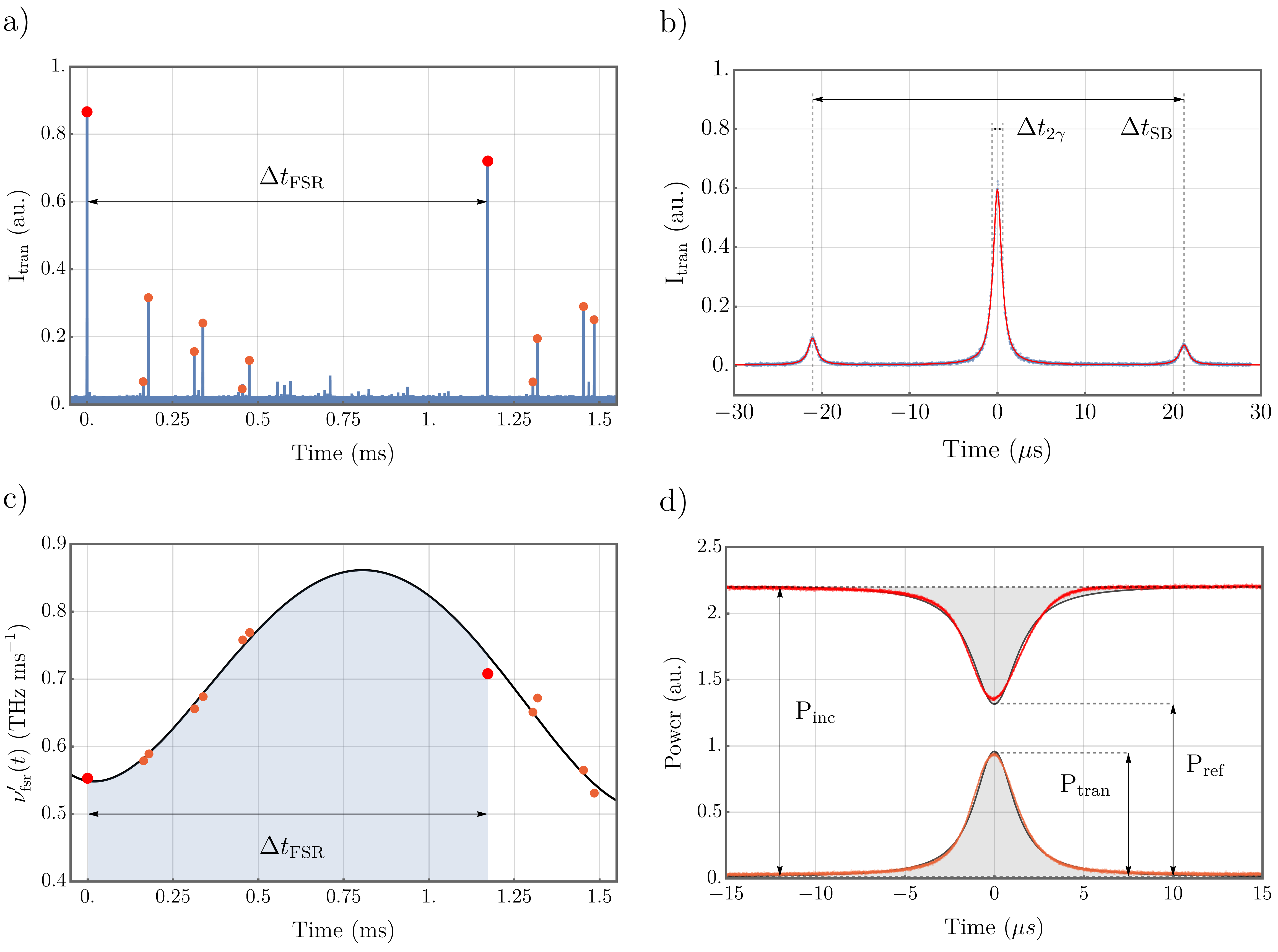
The properties of new mirrors are determined by measuring the finesse in this manner, pairing them with a reference mirror of known characteristics. An illustration of the geometry of this cavity is given as Figure 4c). Two types of super-polished reference mirrors were used, coated for different transmission values, with each being of 50mm radius of curvature and optically characterised by the manufacturer (Research Electro-Optics, Inc.). Following the labelling convention of Figure 5, pyramidal mirrors a) and b) were characterised using a reference mirror with ppm and ppm, giving finesse values of and respectively, corresponding to pyramidal losses of and . Pyramidal mirrors b) and the top right feature of c) were characterised using a reference mirror with ppm and ppm, giving finesse values of and respectively, corresponding to pyramidal losses of and . All errors are calculated statistically.
To determine the transmission of the pyramidal mirror coating and thus isolate their incoherent loss rate, we compare the transmitted optical power from the cavity to the back-reflected power on resonance, following the technique of [40]. For pyramidal mirror b) paired with the high transmission reference mirror, this gave ppm. This highlights that low transmission rates are achievable for the presented design, which may be useful in experiments where directionality of the photonic emission is desired. This can be achieved by constructing the cavity with one mirror with low transmission and another mirror with high transmission, engineered by simply modifying the number of layers in the dielectric stack. Assuming each mirror possesses similar transmission, from the above characterisations we can therefore estimate that the pyramidal mirror possesses scattering and absorption losses of ppm. These losses outweigh the transmission substantially, which is a well-known issue in most cavity implementations using laser-ablated or FIB machined mirrors. However, in combination with low-loss superpolished mirror of 40ppm transmission, our new cavities do nonetheless transmit about half the light from the cavity to outside free-running modes.

In an ideal cavity array, the mirror surfaces have parallel normal axes, such that when paired with an equivalent substrate, the optical modes sit at the centre of each mirror. Any misalignment of these axes, caused by error in ablation beam pointing or underlying curvature of the initial substrate facet, may cause the cavity modes to migrate towards the mirror periphery. To ensure that any such error does not degrade cavity finesse, good optical quality should be achieved across the entire mirror. In combination with atomic force microscopy (AFM) analysis, surface homogeneity was indicated in the finesse measurements described above, via the constant linewidth of several of the higher order modes.
Prior to the application of a reflective coating, scattering losses were predicted by AFM analysis (NaniteAFM, Nanosurf). This highlighted the important role of thermal annealing, clearly visible in Fig 7a). RMS surface roughness was determined over a central area of 2.5m m as nm (see Fig.7b)). Using a demonstrated model [41], this corresponds to scattering losses of ppm, leaving approximately 7ppm to be associated with coating absorption. Absorption of cavity locking light can be known to generate thermal instability of an optical cavity around resonance, especially for FFPCs, but no such effect was observed in the probing of cavity linewidth performed above. Overall, these values are competitive with other laser machined mirrors, for which losses in the range ppm were achieved [42, 12, 27, 18, 43]. In realising an optical quality and geometrical range similar to FFPCs, we outline scope to achieve the favourable atom-cavity coupling parameters observed in such systems. For the transition of Rubidium atoms we estimate the cooperativity to range from 60 for cavities made from mirrors with radius of curvature of 1200 m to 150 for cavities made from mirrors with radius of curvature of 500 m (assuming a Finesse of 78,000). For the transition of Ca+ ions, the cooperativities are estimated to range from 5 and 11 for the respective cavities.
3 Cavity arrays
To mediate a coherent interaction between an atom and a cavity, one must normally tune the cavity resonance to a transition line of the atom. From a technical perspective, this condition may be expressed as a requisite cavity length, with a stability requirement approximated by . For the high-finesse cavities used in strong-coupling experiments, this limit is easily on the order of picometres. The common approach to achieving operational stability is to mount the cavity mirrors on piezoelectric transducers, locking the cavity length to a frequency stable laser via the Pound-Drever-Hall technique [44]. To prevent the reference laser from inducing atomic scattering, it is often far detuned from atomic resonances.
To realise co-resonance of multiple cavity modes to a single optical frequency, and thus simulate co-resonance to an atomic transition, an expansion was made to the experimental architecture of Section 2.3. Here, four cavities are formed from a single bulk substrate hosting four mirror facets, and a near-planar reference substrate, addressed with four independently steerable branches of the frequency stable laser. The translation of the near-planar reference mirror in the cavity axis brings each cavity mode into visible resonance, initially at discordant positions. To control the relative frequency offset between each cavity resonance, the near-planar mirror is rotated in tilt and yaw to change the relative length of the cavities in the array. A rough optimisation of the near-planar mirror angle is performed by bringing each cavity mode towards the centre of the ablated features (by using a camera feed imaging the position of the cavity modes as in Fig.8d)). Fine tailoring of the angles is achieved using piezoelectric actuators while monitoring the resonance signal from a photodetector (Fig. 8a)-c)). A set of demonstrations are given of the control of the frequency of three cavity mode resonances, with fixed spacing. To integrate such a scheme with trapped atoms or ions would require the use of an in-vacuum piezoelectric stage, allowing for curvilinear translation in-situ. While this entails an engineering complexity over that of simple shear piezos for length tuning, the use of similar stages is already in practice for FFPCs [45]. In operation, this stage may also allow to compensate for slow drifts in cavity alignment.
As three points define a plane, the fourth cavity mode cannot be brought into perfect resonance using curvilinear translations. Increasing the number of co-resonant modes would require manufacturing mirror depths to an accuracy of several picometers; well outside the ability of current glass shaping methods. While only a modest number of co-resonant cavity modes increases the utility as an atom-photon interface, for increased scalability one can combine the co-resonant cavities with quantum shift registers, such as re-configurable atom or ion traps, to eventually use cavity-mediated entanglement schemes to produce larger cluster states as a resource for quantum information processing.
Finally, as an expansion to the scheme presented above, cavity length stabilisation may be performed by optical illumination of just one reference cavity from the array, with mode detuning compensated by appropriate frequency shift of the locking laser. For conventional cavity locking schemes which apply continual feedback, the absence of laser light in the atom-resonant cavities would provide benefit in reducing off-resonant scattering rates and unwanted AC stark shifts. Long term stability of such a locking scheme could not be evaluated in the current apparatus, due to the characterisation being performed at atmospheric pressure and the presence of inherent drifts in the 6-axis flexure stage employed.

4 Conclusion
We have developed and characterised an open-access optical cavity array on a single pair of mirror substrates, with mirror templates manufactured using laser ablation. We measured losses of ppm and combined the multi-facet mirror with a super-polished mirror having a transmission rate nearly equal to the losses of the machined substrate, thus allowing access to about half of the photons in the cavity mode. Towards the creation of a multi-emitter cavity quantum interface, we have demonstrated simultaneous laser characterisation of four cavity modes, formed between a pair of substrates. By tuning their respective resonance frequencies with piezoelectric-actuated curvilinear translations, three cavities were placed in simultaneous co-resonance with the addressing laser.
This open-access cavity combines three key advantages of other implementations that were hitherto not simultaneously realised. The first is that it allows the preservation of the spatial mode of the cavity output, allowing for enhanced collection efficiencies as well as full polarisation control. The second is that the macroscopic nature of bulk substrates facilitates the suppression of vibration and effective heat dissipation. This significantly alleviates challenges in stabilising a high finesse cavity’s length to an atomic transition frequency, being perturbed either by mechanical vibration or absorbed heat from the locking laser [46]. The third is the achievement of a low radius of mirror curvature, which gives rise to small cavity mode volumes and extremely strong coupling.
A limitation in using the tapered substrates, which have different facet dimensions, is that the laser ablation procedure needs to be optimised individually owing to a varying heat dissipation rate which is highly dependent on the facet geometry. The rectangular shape of the facets also required additional consideration to compensate for ellipticities that would come about due to the absence of cylindrical symmetry. These issues, however, could be resolved in future implementations by employing selective laser etching techniques [47, 48], to produce substrates of regular dimensions, but also to carve ring cutouts with depths corresponding to the penetration depth of the CO2 laser, in order to restore cylindrical symmetry at the ablation sites.
The presented multi-cavity system could act as several nodes in a quantum network, scaling single photon sources [3] and quantum memories [49]. Or, it could be used to realise schemes which inherently require arrays of atom-cavity systems, such as those for distributed quantum computation [50, 51] or networking [52]. These multi-resonant cavity arrays open up pathways to explore new physics in cavity quantum electrodynamics, such as many-body quantum phenomena [53].
Acknowledgements
The authors would like to acknowledge support for this work from the UK National Quantum Technologies Programme (NQIT hub, EP/M013243/1) and the EU-ITN LIMQUET. This work was supported by JST Moonshot R&D [Grant Number JPMJMS2063].
Disclosures
The authors declare that there are no conflicts of interest related to this article.
Data Availability
Data underlying the results presented in this paper are not publicly available at this time but may be obtained from the authors upon reasonable request.
References
- [1] A. Boca, R. Miller, K. M. Birnbaum, A. D. Boozer, J. McKeever, and H. J. Kimble, “Observation of the vacuum rabi spectrum for one trapped atom,” \JournalTitlePhys. Rev. Lett. 93, 233603 (2004).
- [2] H. J. Kimble, “The quantum internet,” \JournalTitleNature 453, 1023–1030 (2008).
- [3] A. Kuhn, M. Hennrich, and G. Rempe, “Deterministic single-photon source for distributed quantum networking,” \JournalTitlePhys. Rev. Lett. 89, 067901 (2002).
- [4] M. Keller, B. Lange, K. Hayasaka, W. Lange, and H. Walther, “Continuous generation of single photons with controlled waveform in an ion-trap cavity system,” \JournalTitleNature 431, 1075–1078 (2004).
- [5] A. Reiserer, N. Kalb, G. Rempe, and S. Ritter, “A quantum gate between a flying optical photon and a single trapped atom,” \JournalTitleNature 508, 237–240 (2014).
- [6] B. Hacker, S. Welte, G. Rempe, and S. Ritter, “A photon–photon quantum gate based on a single atom in an optical resonator,” \JournalTitleNature 536, 193–196 (2016).
- [7] S. Ritter, C. Nölleke, C. Hahn, A. Reiserer, A. Neuzner, M. Uphoff, M. Mücke, E. Figueroa, J. Bochmann, and G. Rempe, “An elementary quantum network of single atoms in optical cavities,” \JournalTitleNature 484, 195–200 (2012).
- [8] P. R. Dolan, G. M. Hughes, F. Grazioso, B. R. Patton, and J. M. Smith, “Femtoliter tunable optical cavity arrays,” \JournalTitleOpt. Lett. 35, 3556–3558 (2010).
- [9] C. Derntl, M. Schneider, J. Schalko, A. Bittner, J. Schmiedmayer, U. Schmid, and M. Trupke, “Arrays of open, independently tunable microcavities,” \JournalTitleOpt. Express 22, 22111–22120 (2014).
- [10] G. Wachter, S. Kuhn, S. Minniberger, C. Salter, P. Asenbaum, J. Millen, M. Schneider, J. Schalko, U. Schmid, A. Felgner, D. Hüser, M. Arndt, and M. Trupke, “Silicon microcavity arrays with open access and a finesse of half a million,” \JournalTitleLight: Science & Applications 8, 37 (2019).
- [11] N. Jin, C. A. McLemore, D. Mason, J. P. Hendrie, Y. Luo, M. L. Kelleher, P. Kharel, F. Quinlan, S. A. Diddams, and P. T. Rakich, “Micro-fabricated mirrors with finesse exceeding one million,” \JournalTitleOptica 9, 965–970 (2022).
- [12] D. Hunger, T. Steinmetz, Y. Colombe, C. Deutsch, T. W. Hänsch, and J. Reichel, “A fiber Fabry–Perot cavity with high finesse,” \JournalTitleNew Journal of Physics 12, 065038 (2010).
- [13] D. E. Chang, J. S. Douglas, A. González-Tudela, C.-L. Hung, and H. J. Kimble, “Colloquium: Quantum matter built from nanoscopic lattices of atoms and photons,” \JournalTitleRev. Mod. Phys. 90, 031002 (2018).
- [14] J. D. Thompson, T. G. Tiecke, N. P. de Leon, J. Feist, A. V. Akimov, M. Gullans, A. S. Zibrov, V. Vuletić, and M. D. Lukin, “Coupling a single trapped atom to a nanoscale optical cavity,” \JournalTitleScience 340, 1202–1205 (2013).
- [15] M. Harlander, M. Brownnutt, W. Hänsel, and R. Blatt, “Trapped-ion probing of light-induced charging effects on dielectrics,” \JournalTitleNew J. Phys. 12, 93035 (2010).
- [16] M. Brownnutt, M. Kumph, P. Rabl, and R. Blatt, “Ion-trap measurements of electric-field noise near surfaces,” \JournalTitleRev. Mod. Phys. 87 (2015).
- [17] H. Takahashi, E. Kassa, C. Christoforou, and M. Keller, “Strong coupling of a single ion to an optical cavity,” \JournalTitlePhys. Rev. Lett. 124, 013602 (2020).
- [18] J. Gallego, W. Alt, T. Macha, M. Martinez-Dorantes, D. Pandey, and D. Meschede, “Strong Purcell effect on a neutral atom trapped in an open fiber cavity,” \JournalTitlePhys. Rev. Lett. 121, 173603 (2018).
- [19] R. Albrecht, A. Bommer, C. Deutsch, J. Reichel, and C. Becher, “Coupling of a single nitrogen-vacancy center in diamond to a fiber-based microcavity,” \JournalTitlePhys. Rev. Lett. 110, 243602 (2013).
- [20] J. Miguel-Sánchez, A. Reinhard, E. Togan, T. Volz, A. Imamoglu, B. Besga, J. Reichel, and J. Estève, “Cavity quantum electrodynamics with charge-controlled quantum dots coupled to a fiber Fabry–Perot cavity,” \JournalTitleNew Journal of Physics 15, 045002 (2013).
- [21] H. Pfeifer, L. Ratschbacher, J. Gallego, C. Saavedra, A. Faßbender, A. von Haaren, W. Alt, S. Hofferberth, M. Köhl, S. Linden, and D. Meschede, “Achievements and perspectives of optical fiber Fabry–Perot cavities,” \JournalTitleApplied Physics B 128, 29 (2022).
- [22] S. Gao, J. A. Blackmore, W. J. Hughes, T. H. Doherty, and J. F. Goodwin, “Optimization of scalable ion-cavity interfaces for quantum photonic networks,” \JournalTitlePhys. Rev. Appl. 19, 014033 (2023).
- [23] J. Gallego, S. Ghosh, S. K. Alavi, W. Alt, M. Martinez-Dorantes, D. Meschede, and L. Ratschbacher, “High-finesse fiber fabry–perot cavities: stabilization and mode matching analysis,” \JournalTitleApplied Physics B 122, 47 (2016).
- [24] G. K. Gulati, H. Takahashi, N. Podoliak, P. Horak, and M. Keller, “Fiber cavities with integrated mode matching optics,” \JournalTitleScientific Reports 7, 5556 (2017).
- [25] A. R. Peerzada, C. M. Jobson, E. Kassa, J. Morphew, X. Fernandez-Gonzalvo, and M. Keller, “Versatile optical fiber feedthroughs for ultra-high vacuum applications,” \JournalTitleVacuum 180, 109542 (2020).
- [26] S. Nußmann, M. Hijlkema, B. Weber, F. Rohde, G. Rempe, and A. Kuhn, “Submicron positioning of single atoms in a microcavity,” \JournalTitlePhys. Rev. Lett. 95, 173602 (2005).
- [27] C. Saavedra, D. Pandey, W. Alt, H. Pfeifer, and D. Meschede, “Tunable fiber Fabry-Perot cavities with high passive stability,” \JournalTitleOpt. Express 29, 974–982 (2021).
- [28] C. H. Nguyen, A. N. Utama, N. Lewty, K. Durak, G. Maslennikov, S. Straupe, M. Steiner, and C. Kurtsiefer, “Single atoms coupled to a near-concentric cavity,” \JournalTitlePhys. Rev. A 96, 031802 (2017).
- [29] R. Nigmatullin, C. J. Ballance, N. de Beaudrap, and S. C. Benjamin, “Minimally complex ion traps as modules for quantum communication and computing,” \JournalTitleNew Journal of Physics 18, 103028 (2016).
- [30] N. Podoliak, H. Takahashi, M. Keller, and P. Horak, “Comparative numerical studies of ion traps with integrated optical cavities,” \JournalTitlePhys. Rev. Applied 6, 044008 (2016).
- [31] D. Stuart and A. Kuhn, “Single-atom trapping and transport in dmd-controlled optical tweezers,” \JournalTitleNew Journal of Physics 20, 023013 (2018).
- [32] D. Hunger, C. Deutsch, R. J. Barbour, R. J. Warburton, and J. Reichel, “Laser micro-fabrication of concave, low-roughness features in silica,” \JournalTitleAIP Advances 2, 012119 (2012).
- [33] H. Takahashi, J. Morphew, F. Oručević, A. Noguchi, E. Kassa, and M. Keller, “Novel laser machining of optical fibers for long cavities with low birefringence,” \JournalTitleOpt. Express 22, 31317–31328 (2014).
- [34] B. Petrak, K. Konthasinghe, S. Perez, and A. Muller, “Feedback-controlled laser fabrication of micromirror substrates,” \JournalTitleReview of Scientific Instruments 82, 123112 (2011).
- [35] K. Ott, S. Garcia, R. Kohlhaas, K. Schüppert, P. Rosenbusch, R. Long, and J. Reichel, “Millimeter-long fiber Fabry-Perot cavities,” \JournalTitleOptics Express 24, 9839 (2016).
- [36] P. de Groot, “Principles of interference microscopy for the measurement of surface topography,” \JournalTitleAdv. Opt. Photon. 7, 1–65 (2015).
- [37] M. Uphoff, M. Brekenfeld, G. Rempe, and S. Ritter, “Frequency splitting of polarization eigenmodes in microscopic fabry–perot cavities,” \JournalTitleNew Journal of Physics 17, 013053 (2015).
- [38] E. Kassa, W. Hughes, S. Gao, and J. F. Goodwin, “Effects of cavity birefringence in polarisation-encoded quantum networks,” \JournalTitleNew Journal of Physics 25, 013004 (2023).
- [39] M. Fox, Quantum optics (Oxford University Press, 2013).
- [40] C. J. Hood, H. J. Kimble, and J. Ye, “Characterization of high-finesse mirrors: Loss, phase shifts, and mode structure in an optical cavity,” \JournalTitlePhys. Rev. A 64, 033804 (2001).
- [41] J. M. Bennett, “Recent developments in surface roughness characterization,” \JournalTitleMeasurement Science and Technology 3, 1119–1127 (1992).
- [42] S. Garcia, F. Ferri, K. Ott, J. Reichel, and R. Long, “Dual-wavelength fiber Fabry-Perot cavities with engineered birefringence,” \JournalTitleOpt. Express 26, 22249–22263 (2018).
- [43] M. Brekenfeld, D. Niemietz, J. D. Christesen, and G. Rempe, “A quantum network node with crossed optical fibre cavities,” \JournalTitleNature Physics 16, 647–651 (2020).
- [44] E. D. Black, “An introduction to Pound–Drever–Hall laser frequency stabilization,” \JournalTitleAmerican Journal of Physics 69, 79–87 (2001).
- [45] M. Teller, V. Messerer, K. Schüppert, Y. Zou, D. A. Fioretto, M. Galli, P. C. Holz, J. Reichel, and T. E. Northup, “Integrating a fiber cavity into a wheel trap for strong ion-cavity coupling,” \JournalTitlearXiv:2207.10500 (2022).
- [46] J. F. S. Brachmann, H. Kaupp, T. W. Hänsch, and D. Hunger, “Photothermal effects in ultra-precisely stabilized tunable microcavities,” \JournalTitleOpt. Express 24, 21205–21215 (2016).
- [47] J. Masajada, M. Bacia, and S. Drobczyński, “Cluster formation in ferrofluids induced by holographic optical tweezers,” \JournalTitleOpt. Lett. 38, 3910–3913 (2013).
- [48] S. Ragg, C. Decaroli, T. Lutz, and J. P. Home, “Segmented ion-trap fabrication using high precision stacked wafers,” \JournalTitleReview of Scientific Instruments 90, 103203 (2019).
- [49] H. P. Specht, C. Nölleke, A. Reiserer, M. Uphoff, E. Figueroa, S. Ritter, and G. Rempe, “A single-atom quantum memory,” \JournalTitleNature 473, 190–193 (2011).
- [50] L.-M. Duan, B. Wang, and H. J. Kimble, “Robust quantum gates on neutral atoms with cavity-assisted photon scattering,” \JournalTitlePhys. Rev. A 72, 032333 (2005).
- [51] A. Serafini, S. Mancini, and S. Bose, “Distributed quantum computation via optical fibers,” \JournalTitlePhys. Rev. Lett. 96, 010503 (2006).
- [52] M. Uphoff, M. Brekenfeld, G. Rempe, and S. Ritter, “An integrated quantum repeater at telecom wavelength with single atoms in optical fiber cavities,” \JournalTitleApplied Physics B 122 (2016).
- [53] M. Hartmann, F. Brandão, and M. Plenio, “Quantum many-body phenomena in coupled cavity arrays,” \JournalTitleLaser & Photonics Reviews 2, 527–556 (2008).