Movable Antenna-Empowered AirComp
Abstract
A novel over-the-air computation (AirComp) framework, empowered by the incorporation of movable antennas (MAs), is proposed to significantly enhance computation accuracy. Within this framework, the joint optimization of transmit power control, antenna positioning, and receive combining is investigated. An efficient method is proposed to tackle the problem of computation mean-squared error (MSE) minimization, capitalizing on the approach of alternating optimization. Numerical results are provided to substantiate the superior MSE performance of the proposed framework, which establish its clear advantage over benchmark systems employing conventional fixed-position antennas (FPAs).
Index Terms:
Antenna position, mean-squared error (MSE), movable antenna (MA), over-the-air computation (AirComp).I Introduction
In traditional multiple-antenna systems, antennas remain stationary, which imposes limitations on their capacity to fully exploit the spatial variations within a specified transmit/receive region. This limitation becomes particularly pronounced when dealing with a limited number of antennas [1]. In response to this constraint, the concept of movable antennas (MAs) has been introduced [1]. MAs are designed to overcome the constraints associated with conventional fixed-position antennas (FPAs) [1, 2, 3, 4, 5]. They achieve this by connecting to radio frequency (RF) chains via flexible cables and incorporating real-time position adjustment mechanisms [1, 2, 3, 4, 5]. This newfound flexibility empowers MAs to dynamically adapt their positions, thereby reshaping the wireless channel to achieve superior wireless transmission capabilities [1, 2, 3, 4, 5].
Existing research efforts have predominantly focused on exploring the advantages of employing MAs to enhance communication performance [1, 2, 3, 4]. It is pertinent to acknowledge that the additional spatial degrees of freedom afforded by antenna position optimization can yield benefits not only in terms of throughput within communication networks but also in improving data aggregation accuracy within computation networks. Motivated by this broader perspective, our paper delves into the advantages derived from the integration of MAs within over-the-air computation (AirComp) systems. In AirComp systems, each sensor node (SN) is responsible for collecting a single sample of a parameter of interest, such as temperature or humidity. These samples are then transmitted over the wireless channel to a central data fusion center (FC) for subsequent computation [6].
In our investigation, we seek to comprehensively understand how the utilization of MAs can enhance the efficiency and accuracy of these computation processes within AirComp systems. The main contributions of this paper are summarized as follows: i) We propose an MA-empowered uplink AirComp framework that leverages MAs to optimize antenna positions, leading to notable improvements in computation mean-squared error (MSE). ii) We propose an efficient alternating optimization algorithm to tackle the joint design of antenna positioning, receive combining, and power control within the proposed framework. iii) Numerical results reveal that the antenna placement gain offered by MAs significantly improves the MSE performance than conventional FPAs.
II System Model
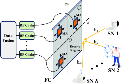
We consider uplink transmission in an MA-empowered AirComp setting where SNs send their collected data simultaneously to an FC for aggregation, as depicted in Figure 1. The FC has receive MAs and each SN has a single transmit FPA. The MAs are connected to RF chains via flexible cables, and thus their positions can be adjusted in real time. The positions of the th MA is denoted by Cartesian coordinates for , where denotes the given two-dimensional receive region within which the MAs can move freely. Without loss of generality, we set as square regions with size .
We assume quasi-static block-fading channels, and focus on one particular fading block with the multi-path channel components at any location in given as fixed. The SN -to-FC channel vector is denotes as . We consider the field-response based channel model given by , where [2, 3, 4, 5]
| (1) |
and where , is the number of channel paths, and are the elevation and azimuth angles of the th path, respectively, is the path loss, denotes the small-scale fading, and is the wavelength. To characterize the performance limit, the FC is assumed to have perfect channel state information [2, 3, 4].
At a specific time slot, we denote as the parameter collected by SN , which satisfies , , and , . Each SN linearly scales its parameter by a power control factor, , and sends to the FC simultaneously [6]. The FC exploits a linear detector to combine the received signal and obtain the computing output of sum of the gleaned parameters , which is expressed as follows: [6]
| (2) |
where is the thermal noise at the FC with being the noise power. The computation distortion is measured by the estimation MSE of , and is given as [6]
Note that different from the FPA-based AirComp, the MSE for the MA-based AirComp depends on the MA positions.
III Solution for MSE Minimization
We aim to minimize the MSE by optimizing the MA positions. The optimization problem is formulated as
| (3a) | |||
| (3b) | |||
| (3c) | |||
where denotes the power budget of SN , is the minimum distance required between each pair of antennas to avoid the coupling effect [2]. Problem (3) is challenging to solve due to the non-convex constraints and tightly coupled variables. To this end, we partition the variable set into distinct blocks . Then, subproblems are solved in the sequel, which respectively optimize , , and , with all the other variables being fixed. The developed algorithm can obtain a locally optimal solution for (3) by iteratively solving the above subproblems in an alternating manner.
Given , the optimal solution of is obtained by solving as
| (4) |
Then, given , the marginal problem for is expressed as . This is a standard convex quadratic optimization problem whose solution is given by . If , we have ; otherwise, we have . The marginal problem for is expressed as follows:
| (5) |
where , , and . Due to the intractability of , stationary points of subproblem (5) can be found capitalizing on the gradient decent method, whose details can found in [4, Section III-A3]. Furthermore, following the steps outlined in [4], it is readily shown that our proposed algorithm involves low computational complexity, which is of a polynomial order.
IV Numerical Results
In this section, numerical results are provided to validate the performance of the proposed MA-empowered AirComp system. Unless otherwise specified, we set , , dB, dBm, , (), and . The elevation and azimuth angles are randomly set within . We compare the performance of our proposed algorithm with the FPA-based benchmark scheme, where the FC is equipped with an FPA-based uniform linear array with antennas spaced by .


In Figure 3, we illustrate the MSE of the proposed and benchmark schemes versus the transmit power . It is observed that with the same power, our proposed algorithm can achieve a lower MSE as compared to the schemes with FPAs. Particularly, when achieving the same MSE, the MA-based scheme is superior to its FPA-based counterpart by a power margin of approximately 3 dB. The MSE performance gain mainly arises from the optimization of MA positions.
Figure 3 plots the MSE versus the normalized region size . It is observed that the proposed schemes with MAs outperform FPA systems in terms of computation distortion, and the performance gain increases with the region size. It is also observed that the MA-based scheme exhibits convergence when the value of exceeds 4. This observation suggests that optimal MSE performance for MA-empowered AirComp systems can be attained within a finite receive region.
V Conclusion
In this paper, we proposed a novel MA-empowered AirComp system to reduce computation distortion. We provided an efficient MSE minimization solution in an MA-based uplink channel by optimizing the receive antenna positions. Simulation results validated the superiority of the proposed MA-based architecture over existing FPA-based ones.
References
- [1] L. Zhu et al., “Movable antennas for wireless communication: Opportunities and challenges,” arXiv:2306.02331, 2023.
- [2] W. Ma et al., “MIMO capacity characterization for movable antenna systems,” IEEE Tran. Wireless Commun., Early Access, 2023.
- [3] L. Zhu et al., “Movable-antenna enhanced multiuser communication via antenna position optimization,” arXiv:2302.06978, 2023.
- [4] Z. Cheng et al., “Sum-rate maximization for movable antenna enabled multiuser communications,” arXiv:2309.11135, 2023.
- [5] W. Ma, L. Zhu, and R. Zhang, “Compressed sensing based channel estimation for movable antenna communications,” IEEE Commun. Lett., Early Access, 2023.
- [6] W. Liu et al., “Over-the-air computation systems: Optimization, analysis and scaling laws,” IEEE Trans. Wireless Commun., vol. 19, no. 8, pp. 5488–5502, Aug. 2020.