Samira Zare
Department of Computer Science and Engineering
University of California Santa Cruz
Modular Self-Lock Origami: design, modeling, and simulation to improve the performance of a rotational joint
Abstract
Origami structures have been widely explored in robotics due to their many potential advantages. Origami robots can be very compact, as well as cheap and efficient to produce. In particular, they can be constructed in a flat format using modern manufacturing techniques. Rotational motion is essential for robotics, and a variety of origami rotational joints have been proposed in the literature. However, few of these are even approximately flat-foldable. One potential enabler of flat origami rotational joints is the inclusion of lightweight pneumatic pouches which actuate the origami’s folds; however, pouch actuators only enable a relatively small amount of rotational displacement. The previously proposed Four-Vertex Origami is a flat-foldable structure which provides an angular multiplier for a pouch actuator, but suffers from a degenerate state. This paper presents a novel rigid origami, the Self-Lock Origami, which eliminates this degeneracy by slightly relaxing the assumption of flat-foldability. This joint is analysed in terms of a trade-off between the angular multiplier and the mechanical advantage. Furthermore, the Self-Lock Origami is a modular joint which can be connected to similar or different joints to produce complex movements for various applications; three different manipulator designs are introduced as a proof of concept.
keywords:
Origami, Rotational joint, Deployable structure, Modular, Crease pattern, Earwig wing, Miura-ori, Spherical mechanisms, Pouch motors, Manipulator1 Introduction
Origami structures have the potential to enhance robotics in various ways. They can help save space jasim2018origami ; tang2014origami ; arya2017crease , reduce energy consumption zhai2020situ ; quaglia2014balancing ; ye2022novel , decrease production time and cost dai2010origami ; onal2011towards ; zhakypov2015design ; yang2017smartphone ; kimionis20153d by offering a compact and lightweight structure, and having a simple flat structure that is easy to produce. Hence, by replacing conventional robotic structures with origami structures, robots could take advantage of these benefits. This paper focuses on an origami rotational joint structure that could substitute the traditional revolute joint norton2008design while offering the advantages of origami.
A variety of origami robots, ranging from legged walkers rus2018design ; mehta2014cogeneration ; mehta2014end ; kohut2013precise ; haldane2013animal ; zhakypov2018design to grippers and more rossiter2014kirigami ; firouzeh2017grasp ; geckeler2022bistable ; chan2017design ; suzuki2020origami , make use of the simple fold as a rotational element in order to build up more sophisticated robots. The simple fold is ideal for these purposes because it is simple and compact. Tendon-driven robogami firouzeh2017under joints with adjustable stiffness using SMP (shape memory polymer) layer could rotate along multiple axes. The joints are flat-foldable and modular. However, the rotational motion has limited range which depends on the solid panels’ thickness and the flexible joint between the panels.
Many rotational joints have been developed beyond the simple fold; some can create limited rotation in multiple different directions koh2012omega ; boyvat2017addressable ; salerno2016novel . Pneumatic origami rotational actuators can produce significant force, but are large and cannot be flat-folded for deployability yi2018customizable . Foldable designs for hinge and pivot joints have been proposed sung2015foldable . These joints can be combined to generate desired kinematics, but they are relatively complicated and cannot be flat-folded. Curved patterns can add stiffness to an origami structure capable of rotational motion zhai2020situ ; taylor2019mr ; baek2020ladybird ; saito2017investigation . A curved kirigami joint has been shown to achieve rotational motion up to almost in multiple directions qiu2021design . In general, curved surfaces generate a low range of rotational motion compared to simple folds. Also, the fold action is impossible due to their geometrical constraints (no fold line).
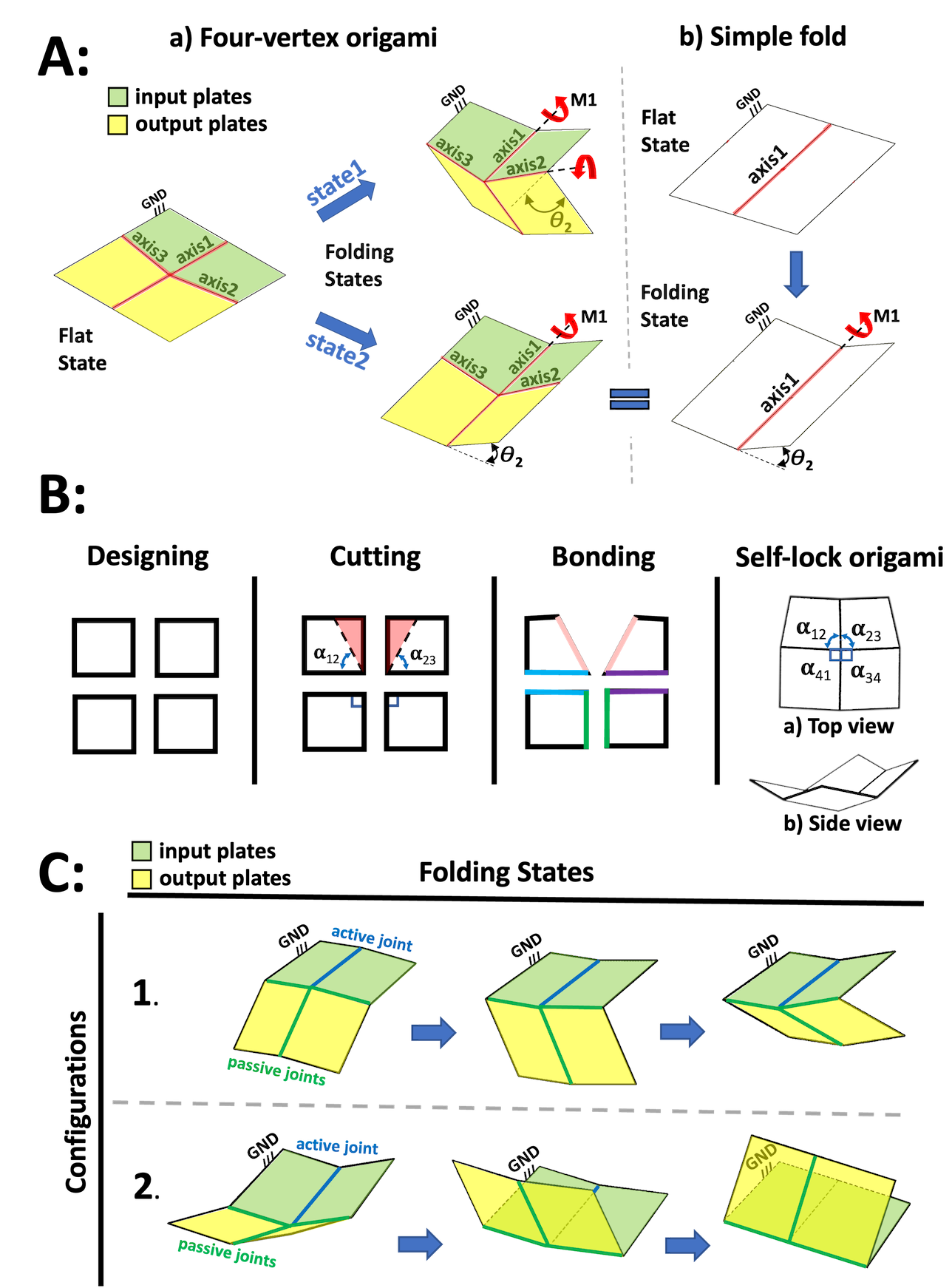
A potential candidate to substitute the traditional rotational linkage in an origami robot is the Four-Vertex Origami, which generates 8.4 times more rotational angle than a simple fold for a given actuator displacement zare2021design . This is crucial when using pouch actuators, which pair naturally with flat-foldable or semi-flat-foldable origami due to their flat shape when deflated, but have a limited range of angular movement niiyama2015pouch . It can be manufactured in different shapes and sizes all the way down to the thickness of a sheet of paper, allowing its weight and size to be adjusted based on the application. Furthermore, it can be assembled with other origami joints to create complex movements brown2022approaches . However, such an origami is underactuated when folded from flat, and in fact has a degenerate state equivalent to a simple fold (figure 1A). The uncertainty of which fold line will be activated when the pouch motor is inflated increases the chance of failure in the joint’s rotation.
Faber et al.faber2018bioinspired designed an earwig-inspired spring origami joint similar to the four-vertex origami but with central angles around the common vertex summing to less than . The flexibility and extensibility of this joint provides a self-lock mechanism during the insect’s flight. However, there is an inherent trade-off in the use of non-rigid origami: the joint spring must be matched precisely to the task, and the stretchability of the fold lines declines over time and with every use. Furthermore, depending on the number of folds, the width of flexible fold lines could be large, resulting in a weaker structure.
This paper proposes a new rigid origami design, the Self-Lock Joint, that combines the Four-Vertex origami zare2021design and the earwig-inspired joint faber2018bioinspired . Reducing the central angles of the origami eliminates the degenerate state of the Four-Vertex origami. Combining with the assumption of a fold line with non-extensible material and zero gaps, the joint could have a deployable structure, save energy, provide a state-lock mechanism, great moment, and downward and upward rotational movements of the structure.
2 Design
The Self-Lock Origami is a rigid origami whose central angles sum to less than . The design consists of four solid adaptable plates connected by four joints (figure 1C), three of which are passive and one of which will be actuated. Figure 1B shows the design and modelling process. First, square-shaped origami plates of side length 25mm are defined. For modelling purposes, these are treated as having zero thickness. Then, the central angles of two of the plates are reduced by drawing a line from one corner of the square (figure 1B) with a specified angle and extending the line until it intersects with the other edge of the square. Revolute joints were then defined at the edges of adjacent plates, indicated with edge colour in figure 1B. These revolute joints are a first-order approximation to the kinematics of a flexible fold line.
2.1 Motion Simulation
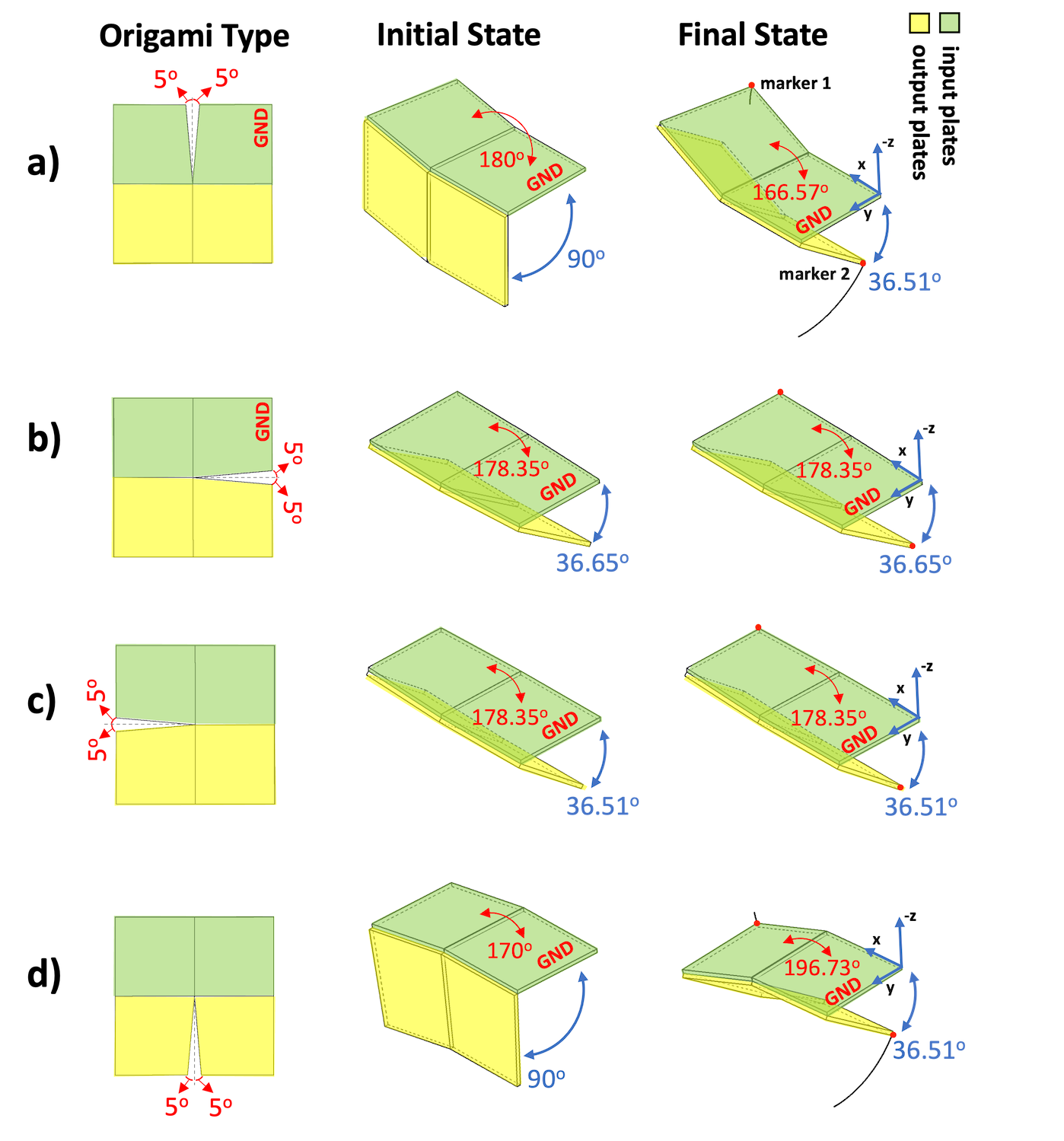
For origami assembly, joint constraints are necessary. Various shapes are created by cutting angles in different origami plates’ positions: any of the origami’s four central angles can be reduced in order to achieve the self-locking property. Although figure 1 demonstrates only one of these, 16 different configurations were considered: four where the central angle was subtracted from both sides of a single fold line (figure 2), and twelve other configurations shown in the supplemental material. Note that only cuts reducing the central angles are considered, as an origami could have various shapes around its edges without compromising its motion zare2021design .
The structure of the grounded plate 1, connected to plate 2, is equivalent to a simple fold (figure 4a). Therefore, the origami’s input angle, , and input moment are the same as the rotational angle and the output moment of a simple fold structure with the same actuator. Different actuators could be used to increase the input angle limits. However, it is not necessary since the output angle changes most for near zero (figure 4). Both the semi-flat and the MPF state occur at values of near . Thus, in order to obtain the full range of motion, there must be pouch motors on both sides of plates 1 and 2.
Various motion simulations were implemented using the contact solver of Autodesk Inventor 2019 to find an origami that could maintain a flat configuration between its input plates at its initial state and obtain the maximum rotational movement (optimal performance). Achieving a flat state by the origami’s input plates could offer a more simplified model and better control by the pouch motor’s actuator. The pouch motor will be able to maintain a zero pressure state (no inflation) and provide a known shape and dimensions at the initial state for the modelling.
In all simulations, plate 1 is a grounded link at a fixed position with its outer corner at the origin. Gravity is neglected for simplicity and consistency with the analytical model. The kinematics of the mechanism are simulated by sweeping the input angle between what the “semi-flat” and “maximum possible fold” (MPF) state. The semi-flat state is defined as the state where the absolute sum of all the angles between origami plates is at its maximum. Since the origami models to have zero thickness, they are kinematically capable of achieving fold angles more extreme than a real origami, so the maximum possible fold state is chosen to set the angle between the input and output plate to the constant MPF angle .
Figure 2 shows origami types defined by different cutting positions. The green and yellow plates are input and output plates respectively. The “initial state” pictured in figure 2 shows the closest angle that origami’s input plates could get to (flat form), and the “final state” is the MPF state. The motion of the outer corners of the input and output plate is shown using markers 1 and 2.
In order to obtain an origami which is symmetrical and also capable of reaching a state with fully flat input plates, origami type a is used in the remainder of the paper. If the flat state of the input plates is not considered, all the origami types provide almost the same amount of rotational motions in slightly different directions. This is discussed in the supplemental material (together with an expanded version of figure 2) using an algorithm described previously zare2021design . Additional fold types not pictured were also considered. Certain of these types could also reach a state with flat input plates, but type a is used due to its symmetry, which simplifies modelling.
3 Modelling
The Self-Lock Origami is a single-vertex origami with four fold lines, meaning that it has a single degree of freedom hull2002modelling ; hull2002combinatorics ; song2016microscale . As shown in figure 1C, the same components can be assembled into two distinct configurations whose motions are vertical mirrors of each other. These configurations can be used in applications to achieve motion in two different directions.
In this section, the relations between the origami’s angles, output moment, input moment, and the pressure in a pouch actuator are developed. Pouch actuators are a practical choice for the Self-Lock Origami because they are planar and compact. They can be treated as a layer of the origami during layer-by-layer construction of an origami robot by programmable machines niiyama2015pouch . The mechanical work of the pouch motor inflation converts into the deformation of its shape and changes in its curvature length. These cause angular motions in the simple fold (a hinged structure) that it has been attached to niiyama2015pouch .
3.1 Origami Structure as a Spherical Mechanism
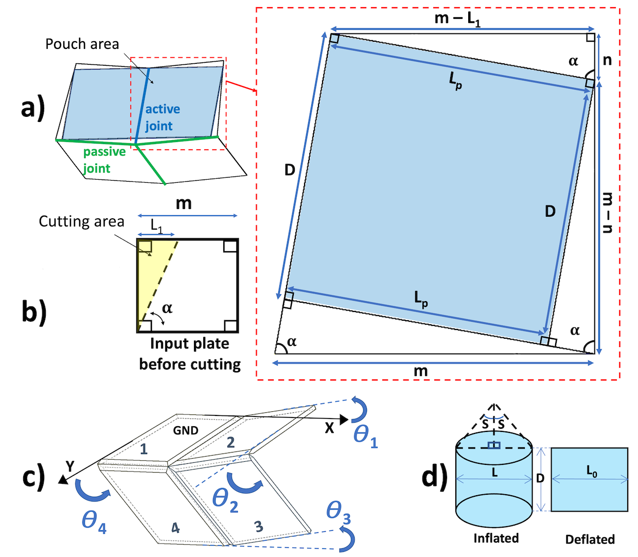
The kinematics and dynamics of single-vertex rigid origami can be studied by noting that they are mechanically identical to spherical mechanisms bowen2014position ; zare2021design , for which a detailed theory exists chiang1988kinematics . To do this, the origami folds between the plates are treated as revolute joints. Then, since each plate of a single-vertex origami is assumed to be inflexible, the single vertex acts as a fixed centre about which the four plates move as the bars of a spherical four-bar mechanism.
The first quantity of interest is the kinematic relationship between the input angle and output angle . The kinematics of a spherical four-bar mechanism are determined entirely by the angular lengths , , , and of its links. Given these quantities, the input and output angles are related by the following equation chiang1988kinematics :
| (1) |
However, the structure of the Self-Lock Origami allows this equation to be simplified significantly. First, the angles and are both equal to , which zeros several terms and simplifies others. The symmetry of the system allows the parameter to be defined, so several more terms can be simplified and combined, resulting in a simple relation between and .
| (2) |
Besides the relation between the input and output angles, the kinematics of the other angles and may also be of interest. Due to the symmetry of the origami, , but . Instead, is calculated using the following relation yang1964application :
| (3) |
Up to angular equivalence, the kinematic equations 2,3 each have two distinct solution curves, corresponding to the two configurations of the Self-Lock Origami. In the up configuration, ranges over positive angles from near zero to almost , whereas in the down configuration ranges over positive angles from near zero to almost . In computations, the atan2 function is used to ensure that the returned value of corresponds to the correct configuration, as the single-argument would result in a discontinuous curve. Using to calculate returns a single continuous positive curve, so the result is simply multiplied by in the down configuration.
3.2 Input and Output Moments
We model the pouch motor as non-extensible with zero bending stiffness. If fully inflated while detached from the origami, it would take a cylindrical form with height , but it is affixed to the origami in its flat state as shown in figure 3, resulting in a rectangular shape with width and height . This length is split between plates 1 and 2, so we also define . The dimensions are chosen to fit the available space on the cut input plates, as shown in figure 3.
The moments that have been applied to (input moment) or generated by (output moment) the origami are modelled under the assumption of constant air pressures on the system’s pouch motor. The moments could be calculated using the origami’s input angle. A range of to degrees has been selected for the input angle, , due to the physical limitation of the pouch motor to produce even near degrees rotational angle. Both upward and downward movements can be created by adding two pouch motors on the origami’s input plates: one on top for range of motion, and another one on the bottom for range of motion.
To estimate the input moment applied to a simple fold (a hinged structure), Niiyama et al. developed equation 4 niiyama2015pouch . The Self-lock origami’s input plates have a structure similar to a simple fold, so this equation can be used to calculate its input moment. Based on the proposed origami structure, the equation relies on the origami’s input angle and . Given the fixed pressure as well as the width , half-length , and central angle of the pouch, the input moment can be calculated as follows:
| (4) |
Here is derived from the assumption that the surface of the pouch acts as a section of a cylinder with constant curvature. The central angle is the angle subtended by the arc of this surface, which depends on and can be approximated well for as follows sun2015self :
| (5) | ||||
and also depend implicitly on the dimensions of the rectangular uninflated pouch. All four plates of the origami were originally squares of side length , but the reduction of central angles to on the input plates reduces the space available for the pouch, as illustrated in figure 3. The length of the top side is reduced by a length , and the misalignment of the right angles of the plates and the pouch means that the top right corner of the pouch touches the side of the plate at one point a distance from its corner. The pouch length and width are then computed geometrically as follows:
| (6) | ||||
Finally, the mechanical advantage of a generic spherical four-bar mechanism has been shown to be calculated as follows (adapted to a different naming convention for central angles) yang1965static :
| (7) |
4 Model Results
This section demonstrates the kinematics of the Self-Lock Origami as well as its input and output moment, including how these quantities and their relationships change with . Figure 4 shows the kinematics of the two configurations of the origami. Figure 4b displays as calculated by solving equation 2, figure 4c shows , which is equal to by symmetry, and figure 4d shows by solving equation 3.
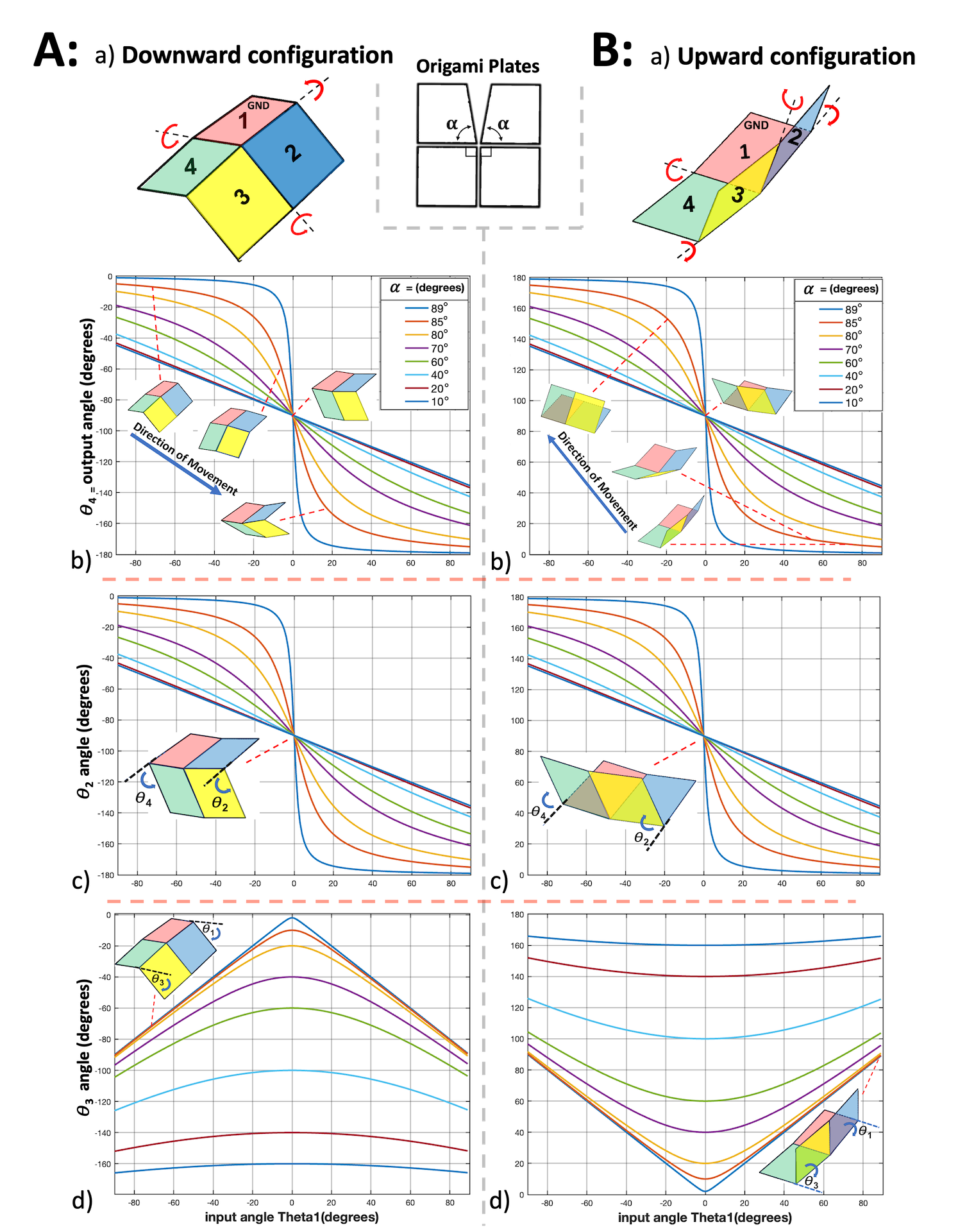
The closer is to , the steeper the slope of the output angle in the regime where is near zero. The total observed range in the output angle is about regardless of the value of . The range of , on the other hand, changes significantly as decreases. This is shown in figure 4d, where the curves for both configurations for various values of are symmetrical about local extrema at . As the angular deficit increases, this extreme value moves further from zero, whereas the overall range and the slope of decrease.
Figure 5 illustrates the theoretical curves 4,7 of input moment and mechanical advantage as a function of for different values of the reduced central angle . Also depicted is the output moment . For the moment study, only one of the origami pouches is considered, since in the typical use case only one pouch will be inflated at a time. The top origami pouch is activated for the downward movement, and for the upward movement, the bottom pouch is. Also, the direction of input and output moments are opposite (figure 5ABa, Downward and upward movements).
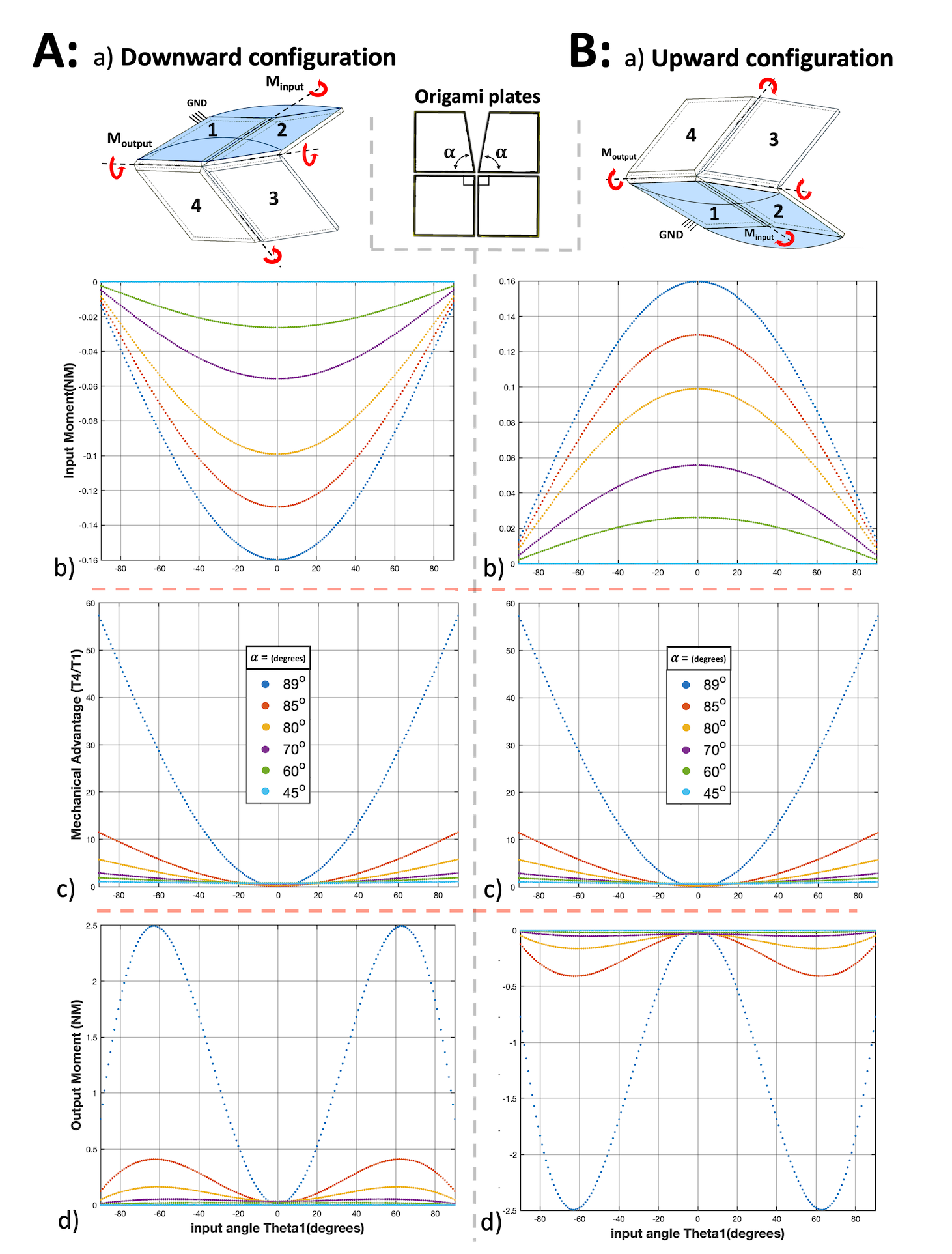
The figure displays curves corresponding to a variety of different values of . Due to the symmetry between the downward and upward configurations of the Self-Lock origami, both the input and output moment differ only by sign between the two configurations. As the input angle changes from to degrees, the absolute value of the input moment changes from zero to its maximum value at degrees since the pouch motors work has not been converted into any motion in this state. As the origami rotates and the input angle gets farther from degrees, the absolute value of the input moment decreases. The shape of this decrease is symmetric about the line. These changes are due to observing the maximum rotational motion near the degrees input angle and the small input moment values near or .
Note that the figure does not consider the effect of varying the pouch pressure . The input moment given by equation 4 depends only linearly on , so all analysis is performed at a constant value . The higher the pressure, the bigger the input and output moments are. However, large pressure values could jeopardise the inextensibility assumption for the pouch motor’s material and result in model failure. Thus the limits of this model’s applicability are determined by the material properties of the pouch motor, which must be constructed from a material with a high Young’s modulus while preserving flexibility properties.
Both downward and upward movements have the same mechanical advantage since they are only different in their moment’s directions. As the input angle increases from negative to positive the mechanical advantage decreases and then increases in a concave shape. The closer plates 1 and 2 get to the flat state ( degrees), the closer the mechanical advantage is to zero since the output moment goes to zero. Crucially, the mechanical advantage is smallest near , exactly where the slope of with respect to is greatest. Therefore, there is a trade-off between the speed and the moment of the origami’s movement. The closer is to , the more this trade-off is taken, with the speed of the origami near zero and the output moment far from zero both increasing dramatically. However, the limiting value is not physically reasonable: at the origami does not function. Similarly, the slope and the mechanical advantage both approach infinity in this limit due to division by zero. Therefore, in the remainder of the paper, the value of where not otherwise stated shall be taken to be , maximising these quantities as well as the flat-foldability of the structure while remaining within a practically realisable regime.
5 Manipulators
As a proof of concept, three different origami manipulators constructed from combinations of multiple Self-Lock Origami units are presented. These manipulators can be divided into three categories: Rotational, Translation, and Modular manipulators. These manipulator concepts can cover a wide range of motions while benefiting from the self-lock structure’s properties, such as compactability, light weight, conserving energy, high-speed rotational motion, and large moment.
Each manipulator is discussed through the results of a kinematic simulation in which the angles of the involved origami joints are swept through a range of angles in order to obtain a desired motion. Dynamics, including gravity, are outside the scope of this section, as are the details of any particular actuation scheme. The rotational and translational manipulators were simulated for different values of the reduced central angle , and the trade-offs involved in choosing a particular value are discussed.
5.1 Rotational Manipulator
The rotational manipulator shown in figure 6 consists of two origami units, connected by a welded joint between one of the output plates of the first origami and one of the input plates of the second origami. Connecting them on more than one plate could jeopardise their mobility; the connection method described here leaves each origami unit with a single degree of freedom. There is a possibility of a collision between the first origami’s output plates and the second origami’s input plates while the manipulators move. To avoid this, the plates are cut at a slight angle in those problematic areas (figure 6Ab). Cutting them does not affect the manipulator’s movements because the plates’ central angles are unaffected. The motion of the manipulator is given in terms of the position of a designated end effector on one corner of the second origami’s output plate, indicated in figure 6A with the red dot labelled “marker”.
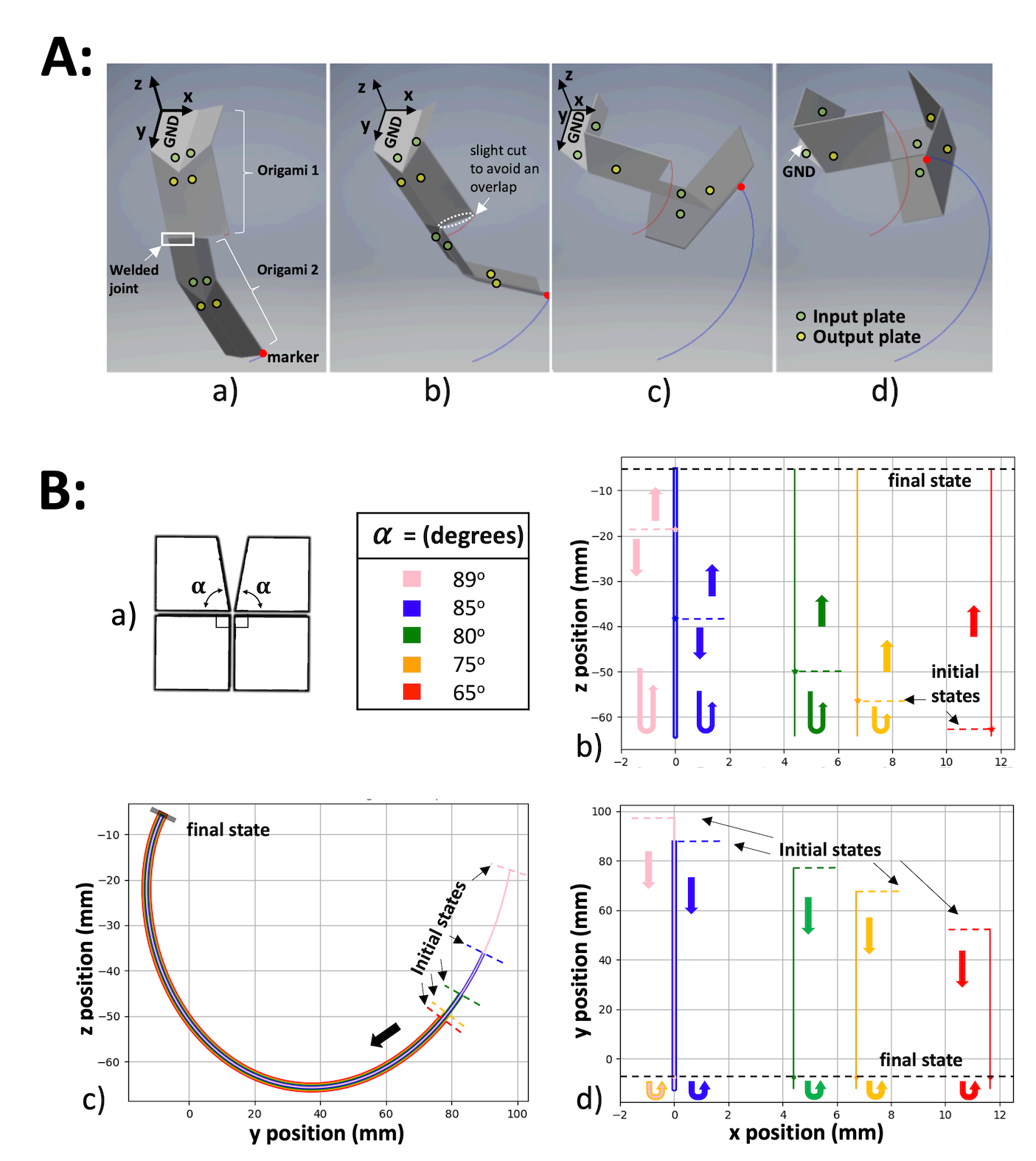
B: a) The origami plates that are used in the manipulator and table of values used for the two Self-Lock Origami units making up the manipulator.
b-d) Motion comparison of manipulator’s end-effector (marker) for different values of the central angle , starting in the origami’s semi-flat state and ending in the maximum possible fold state (see text).
Both of the origami making up the manipulator are constructed in the downwards configuration. Figure 6A gives the coordinate system of manipulators and shows the curling motion in 3D. Figure 6B shows the planar projection of this movement onto the -, -, and - planes. This manipulator is designed to produce a simple rotation about the axis, so the end effector does not move in this direction. However, due to the change in the geometry, the end effector moves further from the line with decreasing . The greater the reduction of the central angles (i.e. the further is from ), the shorter the range of motion on the y-axis. The and degrees manipulators have similar and very close rotation around due to their very small central angle cuts. Due to defining the common MPF state at output angle for all manipulator models, their final states and positions in all plots are the same.
The five manipulators with different values of follow the overall trajectory but with a different initial state, so they all have the same range of motion on the -axis. The larger their central angle cuts are, the bigger the inaccessible configuration area near their flat state. Therefore, their semi-flat configuration (initial state) starts farther away in the range of motion. The movements of different rotational manipulator models in the 3D space are demonstrated in figure S8 in the supplementary material.
5.2 Translational Manipulator
The translational manipulator shown in figure 7 is constructed from four separate origami units alternating downward and upward configurations. This is necessary in order to enable the “zigzag” state depicted in figure 7Aa. To obtain the closest possible motion to a linear translational movement, the manipulator’s geometry is required to be symmetrical. Figure 7Ac shows the location of these connections and cuts.
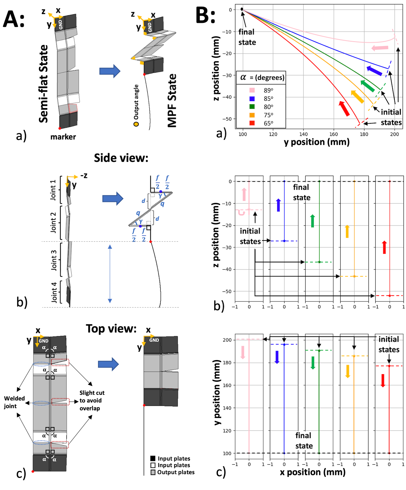
B: a) Top view of the same motion as A. Weld joints and cuts made to avoid overlap between plates are labelled. b) Side view of degrees manipulator’s initial and final state, with the four origami joints indicated individually. Also indicated are the dimensions of the symmetrical zigzag pattern , , , and . C: Two-dimensional workspace of translational manipulators with different values of . Initial and final states are labelled, and direction of motion is indicated with an arrow. They have separate initial states and common final state positions.
Similar to the rotational manipulator, the origamis are connected on only one of their plates to retain the full number of degrees of freedom, and some perimeter cuts are made to avoid overlapping between the origamis’ movements. This manipulator is the only case where plate length deviates from the previously fixed 25mm, as indicated in figure 7Ab. The first and last plates have length 25mm, but the lengths of other plates were derived geometrically. The MPF angle and the desired height of the origami in the MPF state are used to find the plate lengths and .
Figure 7A shows the initial and final states of the manipulator’s translational movement in different views. All origami units start in a semi-flat state and must be actuated simultaneously in order to achieve the depicted straight-line motion. The first and the last joint are folded until reaching a output angle. The second and third joints’ final configurations are MPF. Therefore, as for the rotational manipulator, varying affects the initial but not the final position.
The two-dimensional plots of the manipulators’ movements using a marker and defined reference frame are presented in figure 7C. The main translational movement occurs along the axis, but the end effector does also move somewhat in the axis. In the - plane depicted in figure 7Ba, the manipulator stays closest to the line. The farther the origami models get from , the further their semi-flat state gets from flat. As a result, the range of motion in the axis increases and the axis decreases, and their movements changes from a translational to a somewhat more rotational motion. Among all the translational manipulators, the model produces the closest to ideal translational movement.
5.3 Modular Manipulator
Both manipulators could be combined or their constituent origami units could be actuated in other permutations in order to obtain a combination of translational and rotational motions which could be used for complex tasks. Using the origami design in a modular structure could provide the opportunity to create and mimic traditional robots’ complex movements. This could be useful in exploration, where various motions are required in a limited space. This section explores the possibility of a modular manipulator which combines Self-Lock Origami units in an arbitrary way.
A modular manipulator can be built up from Self-Lock Origami units using two different basic construction cells, depicted in figure 8A. The first consists of two origami connected directly to each other with welded joints and small cutouts to avoid self-collision as discussed previously. The second connects two origami via a rigid “bounding plate” interposed between them. This enables connecting the origami plates at different angles to change or increase the manipulator’s workspace. Bounding plates could be designed in different shapes to help the origami robots to explore different locations, but in the present work only considers a square plate equal in size to the origami units. In the binding phase, constraints are defined for the movements in 3 directions or welded joints to create configurations 1 and 2. Then, the last origami joint is connected to a base plate which serves as the ground link.
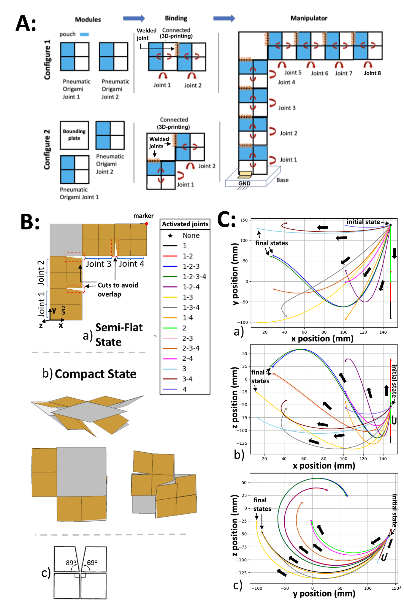
An example of such a modular manipulator made of degrees origami joints is presented in figure 8. By defining different rotational motions on the origami joints, the manipulator could take various shapes in the simulation. Figure 8B shows the manipulator’s compact and semi-flat states with two origami connected at a right angle using a square bounding plate. In the semi-flat state, none of the origami have been activated, and the manipulator is in the closest possible configuration to the flat state. In the compact state, all joints have been activated and folded to the MPF configuration to minimise the overall size of the manipulator. Figure 8Ba additionally indicates the location of the end effector and the coordinate system.
The plots in figure 8C present various possible trajectories which could be taken by this modular manipulator in each of the two-dimensional projections. Each trajectory corresponds to a different sequence of joint activation, indicated in the legend as a sequence of joint numbers. Each joint in the sequence folds from the semi-flat to MPF state, with each fold stopping early if a collision occurs. For instance, activated joints 1-2 refers to folding of joint 1 and then folding joint 2 without overlapping joint 1. The joint activation orders 1-2-3 and 1-2-3-4 have similar motion since after joints 1, 2, and 3 are activated, joint 4 does not have much space for folding.
Across the possible joint folding orders shown, the marker exhibits a large range of motion and a variety of different directions of motion in all three planes. If only the joints on one side of the bounding plate are activated, the end effector trajectory is a a straight line. The joint combination 1-2 generates straight-line movement in both the - and - planes, whereas the joint combination 3-4 produced straight-line motion in the - plane.
One of the advantages of using origami in modular manipulators is the ability to convert them into structures with small volumes due to the joints’ geometries. Manipulators can achieve this by moving their origami into MPF or semi-flat states in different directions. Also, depending on the application, some of the manipulator’s joints can be excluded in order to produce different manipulators. This can even be enforced temporarily, without modifying the manipulator, by simply folding the joints using their actuators and holding them in that state.
6 Conclusions
Origami structures could be a great substitute for traditional joints where space limitation is the main issue. They could adapt their size and shape based on the available space. These computer simulations and mathematical models illustrate the origami structure’s high performance. In different origami states, their motion’s speed and output moment are more significant compared to a simple fold with the same actuator. Increasing the thickness of the origami plates would increase the mechanical strength of the structure, but decrease its flexibility. On the other hand, increasing the soft joint length between the plates increases flexibility while decreasing strength. The trade-off between these characteristics is a potential direction of future research.
As proof of concept, different types of manipulators have been developed and simulated using the origami joints. They could produce a variety of rotational and translational motions depending on their origami’s central angles and configurations. The proposed joint could potentially have many industrial applications, especially in space where the weight and volume of the tools matter the most. It could generate various rotational and translational motions depending on the central angle while maintaining a very lightweight and low fabrication cost due to the flat-foldability properties (simplicity of sheet-like structures for mass production).
One limitation of this work is the assumption of a revolute joint in the design’s analytical modelling. This could result in discrepancies between the experimental and the modelling results. Future work will focus on the development of methods and designs for soft joint production to mitigate the unpredictability of soft materials. This paper has made the assumption that joint angles can be set to a desired value; for physical prototypes, a control scheme is required which combines the kinematic model with sensing and feedback based on the desired end-effector position of the manipulator. Finally, future work will develop methods and experiments to take advantage of this origami joint for real-life applications.
Author Disclosure Statement
No competing financial interests exist. This work was not supported by any organisation.
References
- (1) Jasim B and Taheri P. An origami-based portable solar panel system. In 2018 IEEE 9th Annual Information Technology, Electronics and Mobile Communication Conference (IEMCON). IEEE, pp. 199–203.
- (2) Tang R, Huang H, Tu H et al. Origami-enabled deformable silicon solar cells. Applied Physics Letters 2014; 104(8): 083501.
- (3) Arya M, Lee N and Pellegrino S. Crease-free biaxial packaging of thick membranes with slipping folds. International Journal of Solids and Structures 2017; 108: 24–39.
- (4) Zhai Z, Wang Y, Lin K et al. In situ stiffness manipulation using elegant curved origami. Science advances 2020; 6(47): eabe2000.
- (5) Quaglia C, Yu N, Thrall A et al. Balancing energy efficiency and structural performance through multi-objective shape optimization: Case study of a rapidly deployable origami-inspired shelter. Energy and Buildings 2014; 82: 733–745.
- (6) Ye K and Ji J. A novel morphing propeller system inspired by origami-based structure. Journal of Mechanisms and Robotics 2022; 15(1): 011006.
- (7) Dai J and Caldwell D. Origami-based robotic paper-and-board packaging for food industry. Trends in food science & technology 2010; 21(3): 153–157.
- (8) Onal CD, Wood RJ and Rus D. Towards printable robotics: Origami-inspired planar fabrication of three-dimensional mechanisms. In 2011 IEEE international conference on robotics and automation. IEEE, pp. 4608–4613.
- (9) Zhakypov Z, Falahi M, Shah M et al. The design and control of the multi-modal locomotion origami robot, tribot. In 2015 IEEE/RSJ International Conference on Intelligent Robots and Systems (IROS). IEEE, pp. 4349–4355.
- (10) Yang JS, Shin J, Choi S et al. Smartphone diagnostics unit (sdu) for the assessment of human stress and inflammation level assisted by biomarker ink, fountain pen, and origami holder for strip biosensor. Sensors and Actuators B: Chemical 2017; 241: 80–84.
- (11) Kimionis J, Isakov M, Koh BS et al. 3d-printed origami packaging with inkjet-printed antennas for rf harvesting sensors. IEEE Transactions on Microwave Theory and Techniques 2015; 63(12): 4521–4532.
- (12) Norton RL. Design of machinery: an introduction to the synthesis and analysis of mechanisms and machines. McGraw-Hill/Higher Education, 2008.
- (13) Rus D and Tolley MT. Design, fabrication and control of origami robots. Nature Reviews Materials 2018; 3(6): 101–112.
- (14) Mehta AM, DelPreto J, Shaya B et al. Cogeneration of mechanical, electrical, and software designs for printable robots from structural specifications. In 2014 IEEE/RSJ International Conference on Intelligent Robots and Systems. IEEE, pp. 2892–2897.
- (15) Mehta AM and Rus D. An end-to-end system for designing mechanical structures for print-and-fold robots. In 2014 IEEE International Conference on Robotics and Automation (ICRA). IEEE, pp. 1460–1465.
- (16) Kohut NJ, Pullin AO, Haldane DW et al. Precise dynamic turning of a 10 cm legged robot on a low friction surface using a tail. In 2013 IEEE International Conference on Robotics and Automation. IEEE, pp. 3299–3306.
- (17) Haldane DW, Peterson KC, Bermudez FLG et al. Animal-inspired design and aerodynamic stabilization of a hexapedal millirobot. In 2013 IEEE International Conference on Robotics and Automation. IEEE, pp. 3279–3286.
- (18) Zhakypov Z and Paik J. Design methodology for constructing multimaterial origami robots and machines. IEEE Transactions on Robotics 2018; 34(1): 151–165.
- (19) Rossiter J and Sareh S. Kirigami design and fabrication for biomimetic robotics. In Bioinspiration, Biomimetics, and Bioreplication 2014, volume 9055. SPIE, pp. 105–112.
- (20) Firouzeh A and Paik J. Grasp mode and compliance control of an underactuated origami gripper using adjustable stiffness joints. Ieee/asme Transactions on Mechatronics 2017; 22(5): 2165–2173.
- (21) Geckeler C and Mintchev S. Bistable helical origami gripper for sensor placement on branches. Advanced Intelligent Systems 2022; 4(10): 2200087.
- (22) Chan YH, Tse Z and Ren H. Design evolution and pilot study for a kirigami-inspired flexible and soft anthropomorphic robotic hand. In 2017 18th international conference on advanced robotics (ICAR). IEEE, pp. 432–437.
- (23) Suzuki H and Wood RJ. Origami-inspired miniature manipulator for teleoperated microsurgery. Nature Machine Intelligence 2020; 2(8): 437–446.
- (24) Firouzeh A and Paik J. An under-actuated origami gripper with adjustable stiffness joints for multiple grasp modes. Smart Materials and Structures 2017; 26(5): 055035.
- (25) Koh JS and Cho KJ. Omega-shaped inchworm-inspired crawling robot with large-index-and-pitch (lip) sma spring actuators. IEEE/ASME Transactions On Mechatronics 2012; 18(2): 419–429.
- (26) Boyvat M, Koh JS and Wood RJ. Addressable wireless actuation for multijoint folding robots and devices. Science Robotics 2017; 2(8): eaan1544.
- (27) Salerno M, Zhang K, Menciassi A et al. A novel 4-dof origami grasper with an sma-actuation system for minimally invasive surgery. IEEE Transactions on Robotics 2016; 32(3): 484–498.
- (28) Yi J, Chen X, Song C et al. Customizable three-dimensional-printed origami soft robotic joint with effective behavior shaping for safe interactions. IEEE Transactions on Robotics 2018; 35(1): 114–123.
- (29) Sung C and Rus D. Foldable joints for foldable robots. Journal of Mechanisms and Robotics 2015; 7(2): 021012.
- (30) Taylor AJ, Slutzky T, Feuerman L et al. Mr-conditional sma-based origami joint. IEEE/ASME Transactions on Mechatronics 2019; 24(2): 883–888.
- (31) Baek SM, Yim S, Chae SH et al. Ladybird beetle–inspired compliant origami. Science Robotics 2020; 5(41): eaaz6262.
- (32) Saito K, Nomura S, Yamamoto S et al. Investigation of hindwing folding in ladybird beetles by artificial elytron transplantation and microcomputed tomography. Proceedings of the National Academy of Sciences 2017; 114(22): 5624–5628.
- (33) Qiu L, Yu Y and Liu Y. Design and analysis of lamina emergent joint (lej) based on origami technology and mortise-tenon structure. Mechanism and Machine Theory 2021; 160: 104298.
- (34) Zare S and Teodorescu M. Design and analysis of plate angles of the four-vertex origami pattern and its impacts on movement of rotational joints. Smart Materials and Structures 2021; 30(9): 095012.
- (35) Niiyama R, Sun X, Sung C et al. Pouch motors: Printable soft actuators integrated with computational design. Soft Robotics 2015; 2(2): 59–70.
- (36) Brown NC, Ynchausti C, Lytle A et al. Approaches for minimizing joints in single-degree-of-freedom origami-based mechanisms. Journal of Mechanical Design 2022; 144(10): 103301.
- (37) Faber JA, Arrieta AF and Studart AR. Bioinspired spring origami. Science 2018; 359(6382): 1386–1391.
- (38) Hull TC et al. Modelling the folding of paper into three dimensions using affine transformations. Linear Algebra and its applications 2002; 348(1-3): 273–282.
- (39) Hull T. The combinatorics of flat folds: a survey. In Origami3: Proceedings of the 3rd International Meeting of Origami Science, Math, and Education. pp. 29–38.
- (40) Song Z, Lv C, Liang M et al. Microscale silicon origami. Small 2016; 12(39): 5401–5406.
- (41) Bowen LA, Baxter W, Magleby SP et al. A position analysis of coupled spherical mechanisms found in action origami. Mechanism and Machine Theory 2014; 77: 13–24.
- (42) Chiang CH. Kinematics of spherical mechanisms. Cambridge University Press, 1988.
- (43) Yang AT and Freudenstein F. Application of dual-number quaternion algebra to the analysis of spatial mechanisms. Journal of Applied Mechanics 1964; 31(2): 300–308.
- (44) Sun X, Felton SM, Niiyama R et al. Self-folding and self-actuating robots: A pneumatic approach. In 2015 IEEE International Conference on Robotics and Automation (ICRA). IEEE, pp. 3160–3165.
- (45) Yang AT. Static force and torque analysis of spherical four-bar mechanisms. Journal of Engineering for Industry 1965; 87(2): 221–227.
7 Nomenclatures
| Angle subtended by one arc-shaped side of the inflated pouch actuator. | |
| Angular deviation of plates 2 and 3 from coplanar. | |
| Angular deviation of plates 3 and 4 from coplanar. | |
| Central angle of plate 1 of the origami, here set to . | |
| Central angle of plate 2 of the origami, here set to . | |
| Central angle of plate 3 of the origami, here always equal to . | |
| Central angle of plate 4 of the origami, here always equal to . | |
| Distance from the corner of the plate where the corner of the pouch actuator meets the edge of the plate. | |
| Fixed pressure within the pouch actuator. | |
| Half-length of the pouch actuator when flat, equal. | |
| Height of an origami cell in its MPF state in the translational manipulator. | |
| Input angle, the angular deviation of plates 1 and 2 from coplanar. | |
| Input moment created directly by the pouch motor. | |
| Length of the inflated pouch actuator. | |
| Length of the pouch actuator when flat, equal to . | |
| Length removed from the far side of plates 1 and 2 by cutting. | |
| Length of the sides of the input plate before cutting. | |
| MPF | Maximum Possible Fold, the state where . |
| MA | Mechanical advantage of the origami structure, defined as . |
| Output angle, the angular deviation of plates 1 and 4 from coplanar. | |
| Output moment created by the pouch motor through the mechanical advantage of the origami. | |
| Reduced value of central angles and . | |
| Value of in the MPF state. | |
| Width of the horizontal components of the ”zigzag” configuration of the translational manipulator. | |
| Width of the pouch actuator when flat. |