Mode shapes and sensitivity analysis of torsional vibrations in overhang- and T-shaped microcantilevers
Abstract
The torsional mode of atomic force microscope (AFM) cantilevers plays a crucial role in a wide range of sensitive measurements. Despite their importance, the use of approximated frequencies and mode shapes for width-varying cantilevers often results in discrepancies between theoretical models and experimental observations. In this study, we present an analytical approach to accurately calculate the mode shapes and resonance frequencies of these cantilevers, including higher-order modes, then we derive the modal sensitivity. Our results reveal distinct changes in mode shapes and frequencies as the overhang length increases, with the mode shapes showing multiple maxima. Furthermore, we demonstrate that tuning the overhang length provides effective control over the resonant frequency. The relationship between modal sensitivity and the coupling strength between the cantilever and the surface is also established, aligning with previous experimental findings. This work offers valuable insights for optimizing cantilever geometry to achieve desired frequency responses in AFM applications.
I Introduction
Atomic force microscopy (AFM) has become a powerful tool for high-resolution surface topography characterization and single-molecule force spectroscopy, offering exceptional sensitivity and reliability [1, 2]. By monitoring cantilever deflections or shifts in resonant frequency, AFM enables analysis of structural, thermal, and mechanical properties of various materials [3, 4]. AFM cantilevers can operate in diverse environments such as air, gas, and liquid [5], and recent advances have improved their dynamic response, broadening the range of applications [6]. Although the flexural vibration mode is widely used, torsional vibration modes have garnered increasing interest due to their potential for new measurement techniques and applications [7, 8]. Turner et al. [9] demonstrated that torsional modes provide improved sensitivity for surfaces with high stiffness, particularly when higher-order modes are considered. Torsional modes are particularly suited for measuring lateral stiffness on material surfaces, as highlighted by recent work on cantilevers with sidewall probes [10]. A study by Sharos et al. showed that the mass sensitivity of the torsional mode in micro-cantilevers is higher than that of the bending mode. [11].
Beyond the simple rectangular beam, more complex geometries, such as inverted T-shaped or V-shaped cantilevers [12, 13] , have attracted considerable interest. However, determining the exact frequency and mode shapes of these structures poses significant challenges due to their non-uniform width and thickness. Zhang et al. [14] investigated the deflection and resonant frequency of cantilevers with variable widths, using polynomial approximations to overcome the difficulty of solving the Euler-Bernoulli equation analytically. While their approach revealed a strong dependence of frequency on geometric parameters, the solutions were cumbersome and sensitive to the polynomial assumptions. Plaza et al. [12] demonstrated that placing microcantilevers in arrays could reduce initial deflections, but accurate frequency determination still relied on experimental methods. Thus, an analytical formula for the frequency of cantilevers with varying widths remains a critical area of interest. Particularly, the information on the overhang part as the transition region contributes to the design of cantilever geometries to achieve desired performance characteristics, such as enhanced resolution in material surface topography. Additionally, this work can provide valuable insight for array systems where cantilevers are coupled through the overhang section, opening a detailed calculation of the effects of geometric factors and enabling accurate computation of coupling strength—an essential parameter for detection applications. A recent study showed that the coupling strength between cantilevers in an array is linear dependent on the overhang length and inversely cubic dependent on the overhang width [15]. Moreover, an array structure, where the cantilevers are connected through an overhang and they have the same thickness, shows a significant potential for detection applications [16, 17, 18]. The results in the current paper will reduce the discrepancies between the experimental and analytical frequencies of the overhang-type cantilevers.
Modifications to beam geometry can significantly alter dynamic behavior and lead to the appearance of higher harmonic frequencies [4]. Researchers have explored various cantilever geometries to optimize deflection and frequency characteristics. For example, Payam et al. [19, 20] investigated the flexural spring constant of cantilevers with different shapes in fluid environments, while Plaza et al., explored T-shaped structures to minimize initial angular deviations [12].
In this work, we investigate how changes in the mode shapes and frequencies of overhang-shaped and T-shaped cantilevers influence their sensitivity. We specifically focus on the effects of varying the dimensions of the overhang and T-shaped sections.
In Section II, we derive the frequency equations for T-shaped cantilevers, disregarding external interactions, to demonstrate how frequency and mode shapes evolve with changes in the overhang and T-part dimensions. Results and analyses are presented in Section III with a dedicated exploration of modal sensitivity in Section III.3 considering interactions with a sample through an effective rigidity . Finally, conclusions are drawn in Section IV.
II Material and Methods
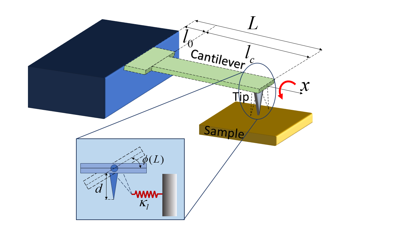
The cantilever is assumed to made from silicon nitride [8] as in conventional experiments with a length = 200–500 m, a width = 35 m and a thickness = 1.5 m. Based on the analytical method that effectively described the flexural vibration of the nonuniform cross-section cantilevers presented in Refs. [15, 21], we considered the torsional vibration of the cantilever with overhang-shaped and T-shaped structures [see Fig. 1]. We examined the effects of the overhang- and T-part dimension on the frequency and mode shape of the beam. Furthermore, we realized that different torsional modes significantly affect the vibration process. Therefore, a detailed analysis on the multi-mode behavior of the cantilever is required.
The dynamic equation for the torsional vibration mode is written based on the Euler-Bernoulli theory of the beam [22, 23] as follows:
| (1) |
where is the deflection angle at position and time . is the shear modulus and is the density of the beam. and are geometric functions of the beam cross section and the polar moment of inertia, respectively. Here, the cross section of the beam is a rectangle shape, hence, and . It is shown that the width of the beam is -dependent. Hence, the general solution of Eq. (1) is . Input it back to Eq. (1), one obtains the equations for the mode shape (-dependent) and for the frequency. The mode shape equation reads,
| (2) |
For the current cross-section of the beam, the thickness of the overhang part and the outer cantilever part are assumed to be the same while the width is steplike with ,
| (3) |
Based on Eq. (3), Eq. (2) is divided into two equations. The first equation describes the overhang part,
| (4) |
and the second equation is for the cantilever part,
| (5) |
Here, is the characteristic frequency. Now, the frequency ratio is
| (6) |
or, could be used for brevity. The solutions Eqs. (4) and (5) could be written as follows,
| (7) |
and
| (8) |
The boundary conditions are
| (9) |
The continuous conditions written at are
| (10) |
and
| (11) |
From these conditions, a matrix equation has been obtained as follows,
| (12) |
where is written as
| (13) |
where, , , and . It could be shown that the matrix will give rise to the solution presenting the cantilever frequency and mode shape if the eigenvalue and eigenvector exist. Hence, from , we obtain a frequency equation,
| (14) |
which is used to derive the the frequency of beam via ,
| (15) |
Obtaining the four coefficients , , , and , the mode shape is presented as,
| (16) | ||||
| (17) |
The updated mode shapes, in the case of flexural vibration, have been shown to significantly modify that of the uniform cross-section cantilevers [21]. For the torsional modes, similar behavior is expected.
III Results
Typical microcantilever dimensions fall within the following ranges: length () from 50 to 500 m, width () from 10 to 50 m, and thickness () from 0.5 to 5 m. For example, Etayash and Thundat utilized typical geometric parameters for silicon microcantilevers with lengths ranging from 100 to 500 m, widths from 20 to 50 m, and thicknesses between 0.3 and 2 m [24]. In another study by McFarland et al., the microcantilever had a length of approximately 500 m, a width of 97.2 m, and a thickness of 0.8 m [25]. We present the change in mode shape and frequency of a microcantilever using silicon nitride as a typical material with the parameters shown in Table 1.
| Parameters | Symbol (Unit) | Value | |
|---|---|---|---|
| Length | (m) | 350 | |
| Width | (m) | 35 | |
| Thickness | (m) | 1.5 | |
| Young’s modulus | (GPa) | 169 | |
| Density | (kg/) | 2300 |
III.1 Changes in mode shapes
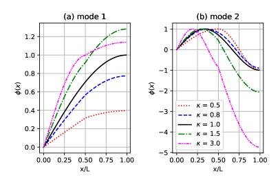
The mode shapes have been expressed in Fig. 2 with (a) for the first mode and (b) for the second mode. Figure 2(a) and 2(b) are presented for and various values of overhang widths, = 1.0 by black-solid, 0.5 by red-dotted, 0.8 by blue dashed, 1.5 by green dash-dotted, and 3.0 by pink dash-dot-dotted lines. The deflection angle at , , has been shown to tend to increase as the width of the cantilever increases.
Especially, for the second mode, the mode shapes of = 0.5–0.8 deviate from that of for 0 with a maximum then decrease and approach the value -1 in , while those of greatly decrease (green dash-dotted lines and pink dash-dotted lines).
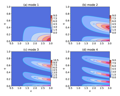
A summary of the behavior of the first four modes is sketched in Fig. 3 to show the effect of the overhanging part on the deflect angle at the free end of the beam. Noting on the intensity of the color, which is proportional to the magnitude of the deflection, we could see that there are some maxima for the deflection. First, the number of maxima is proportional to the mode number, e.g. the 2nd mode has two maxima at 0.05 and 0.4 (red region), the 3rd mode has three maxima at 0.025, 0.2, and 0.6, and the 4th mode has maxima at 0.01, 0.15, 0.3, and 0.65.
III.2 Changes in frequency
Examining the change in the cantilever frequency , we obtained an interesting behavior in which the decrease in versus the reduction in the length of the overhang is nonmonotonic. The first mode first increases [Fig. 4(a)] and gets a maximum at 0.2 then reduces rapidly when increases. In the maxima (orange to red) region, the frequency increases with , i.e. with the bigger overhang (implying a stiffer cantilever).
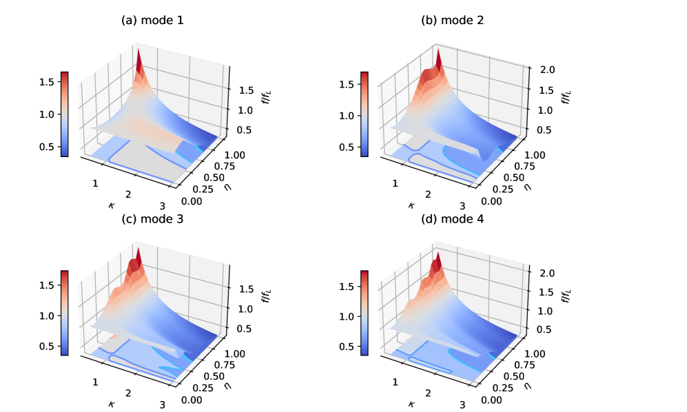
The 2nd to 4th modes, on the other hand, no longer clearly present the maximal region. All frequencies tend to decrease rapidly as they increase . For example, within the range = 0–0.5, the second mode [Fig. 4(b)] reduces significantly from 1.0 to 0.5 (1000 to 500 kHz). The 3rd and 4th [Fig. 4(c) and (d)] modes have a small maximum before reducing to low frequency. These findings are interesting for the following reasons. First, there is a nearly flat plateau in the frequency response alongside a rapid decrease. This feature could be useful for controlling and tuning the cantilever frequencies by adjusting the length of the overhang part, thereby enhancing the high-harmonic frequencies [26, 4]. Second, an effective modulation of the higher-order modes, relying on the structure’s geometry, could enhance the possibility of utilizing various modes in measurements, improve mode coupling, and even enable the appearance of high harmonics (as the higher-order mode frequencies can be integer multiples of the lower frequencies). Consequently, appropriate parameters of the overhang part can be used to facilitate the tuning of higher modes.
III.3 Torsional sensitivity
The sensitivity of the flexural modes of overhanged and T-shaped cantilevers has recently been examined [20], demonstrating that the dimensions of the overhang part can significantly alter the cantilever’s frequency. For torsional modes, several studies have been conducted by Abbasi et al. [27] on cantilevers with sidewall probes for rectangular geometries. However, the torsional vibrations of overhang- or T-shaped cantilevers have not yet been investigated.
Here, we analyze the torsional modal sensitivity of the overhang-shaped cantilever, assuming a tip-sample interaction modeled as a linear lateral spring with stiffness . This interaction is applied at the cantilever’s end position, . The boundary condition at the position was written as , where . This leads to the interplay part appearing in the matrix in Eq. (13). The matrix was rewritten as follows [Eq. (18)],
| (18) |
Similarly, using the updated matrix , a characteristic equation was obtained by calculating the determinant of the matrix. Finally, a characteristic equation for the frequency is obtained,
| (19) |
where
| (20) | ||||
| (21) |
and present the non-contact the contact part, subsequently. The change in frequency versus and coupling stiffness is shown in Fig. 5 for the first and second modes. It has been seen that, for , first decreases and then increases with while for , the trend is inverted. Especially, there exists a balance point where = 1 for every value of . This is interesting because one could choose a length and width of an overhang- and T-shaped cantilever that gives rise to a same torsional frequency as that of a rectangular one. In other words, we could use such points as a reference for the width-varying cantilever.
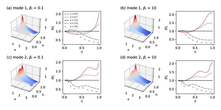
Increasing the coupling stiffness makes the frequency alter more fastly, e.g., for 1st mode [see Fig. 5(b)] it sooner cuts the line and increases () to reach a maximal value (red dashed and blue dotted lines) or decreases () to reach a minimal value (violet long dashed and green dash-dotted lines). For higher mode, other extrema could appears, which is similar to the trend stated in Fig. 4.
The sensitivity is defined as the change in the frequency versus the interaction strength [9],
| (22) |
Here, the frequency of the beam is computed by
| (23) |
Then, the normalized torsional sensitivity is obtained.
| (24) |
where
| (25) |
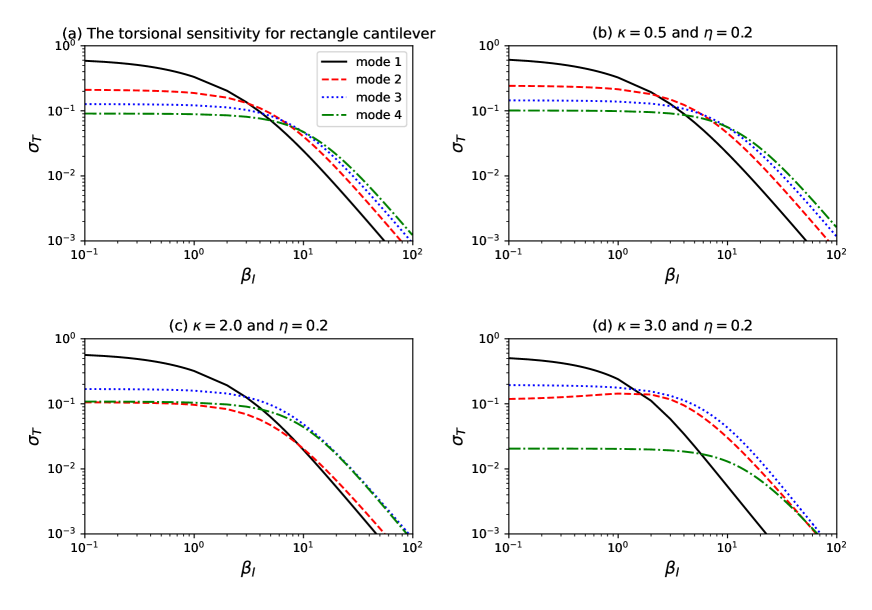
The normalized torsional modal sensitivity is shown in Fig. 6: (a) for the rectangular, (b) for the T-shaped, (c) for the overhang-shaped, and (d) for the wider overhang-shaped cantilevers. Here, is used. It is recognized that the formulation of the sensitivity of a rectangle cantilever has been obtained if the geometric ratios were set or , and the analytical calculation of Turner et al. is realized [9].
First, a similar behavior of the modal sensitivity () of a rectangular cantilever with that of Turner et al. [9] is reproduced in Fig. 6(a) with a note that here are slightly higher because a longer length of = 350 m has been used [Tunner used a 200 m-long cantilever].
Then, for the T-shaped cantilevers [Fig. 6(b)], is slightly altered, while that of the overhang-shaped cantilevers [Fig. 6(c)–(d)] is significantly changed. of the 1st mode (black solid line) decreases faster than that of the higher modes, and of the 4th mode remains stable in a wide range of (green dash-dotted line). Especially, with low , the 3rd mode (blue dotted lines) increases its sensitivity and becomes higher than that of the 2nd mode, which is clearly different from the sensitivity order, , of rectangular and T-shaped cantilevers. Furthermore, an increase in sensitivity is observed only for the second mode, in the range = 1–10. This is different from the conventional behavior in which the sensitivity usually increases in the range of = 1–100 depending on the mode number before rapidly decreasing to zero for higher , as shown by Ref. [9] for the torsional modes and Refs. [28, 20] for the flexural modes. However, to improve the dynamics and also the sensitivity of the torsional modes, a cantilever with a (extended) side wall probe could be used [29], as it has been shown to have interesting behavior depending on the dimensions of the extended probe [10]. We will consider this subject in a later work.
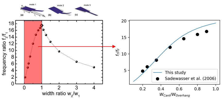
Our approach demonstrated strong agreement with prior research on the frequency and sensitivity of cantilevers. For example, Sadewasser et al. investigated the dynamics of cantilevers with an overhang section [30]. Compared to Sadewasser’s results, our method showed excellent consistency in the ratio between the torsional () and flexural () frequencies under identical geometric parameters, as illustrated in Fig. 7.
IV Conclusions
In this study, we analytically derived the frequency characteristic equations and modal sensitivities for the torsional modes of overhang- and T-shaped cantilevers. Our results reveal significant and effective changes in both mode shape and frequency as functions of the overhang length, providing a versatile framework for selecting dimensional parameters to achieve specific performance characteristics. Notably, we presented a detailed analysis of the modal sensitivity of these cantilevers for the first time. Our analytical findings align with previous studies and extend the analysis to overhang-shaped cantilevers. These insights offer valuable guidance for experimentalists in designing cantilever structures with tailored frequencies and sensitivities, enabling highly sensitive measurements across a range of applications.
Acknowledgements
We thank Amir F. Payam (Ulster University) for fruitful discussion and encouragement.
The data in my manuscript can be obtained from the corresponding author upon reasonable request.
References
- [1] Neuman K C and Nagy A 2008 Nat. Methods 5 491–505 URL https://www.nature.com/articles/nmeth.1218
- [2] Sajjadi M, Pishkenari H N and Vossoughi G 2017 Ultramicros. 182 99–111 ISSN 0304-3991 URL http://dx.doi.org/10.1016/j.ultramic.2017.06.009
- [3] Rezapour B, Araghi M A F and Vázquez-Leal H 2021 J. Vib. Control 27 802–814 URL https://doi.org/10.1177/1077546320933478
- [4] Dat L T, Nguyen C C, Vy N D and Payam A F 2023 Jpn. J. Appl. Phys. 62 107002 URL https://dx.doi.org/10.35848/1347-4065/ad00a0
- [5] Karimpour M, Ghaderi R and Raeiszadeh F 2017 Micron 101 213–220 ISSN 0968-4328 URL https://www.sciencedirect.com/science/article/pii/S0968432817301488
- [6] Vy N D and Iida T 2015 Appl. Phys. Express 8 032801 URL https://dx.doi.org/10.7567/APEX.8.032801
- [7] Heinze K, Arnould O, Delenne J Y, Lullien-Pellerin V, Ramonda M and George M 2018 Ultramicros. 194 78–88 ISSN 0304-3991 URL https://www.sciencedirect.com/science/article/pii/S030439911730308X
- [8] Mohammadi S Z, Moghadam M and Pishkenari H N 2019 Ultramicros. 197 83–94 ISSN 0304-3991 URL http://dx.doi.org/10.1016/j.ultramic.2018.11.017
- [9] Turner J A and Wiehn J S 2001 Nanotechnology 12 322 URL https://dx.doi.org/10.1088/0957-4484/12/3/321
- [10] Payam A F and Duy Vy N 2021 Microsc. Res. Tech. 84 782–788 URL https://analyticalsciencejournals.onlinelibrary.wiley.com/doi/abs/10.1002/jemt.23636
- [11] Sharos L B, Raman A, Crittenden S and Reifenberger R 2004 Applied Physics Letters 84 4638–4640 ISSN 0003-6951 (Preprint eprint https://pubs.aip.org/aip/apl/article-pdf/84/23/4638/18589520/4638_1_online.pdf) URL https://doi.org/10.1063/1.1759379
- [12] Plaza J A, Zinoviev K, Villanueva G, Álvarez M, Tamayo J, Domínguez C and Lechuga L M 2006 Appl. Phys. Lett. 89 094109 URL https://doi.org/10.1063/1.2345234
- [13] Sader J E, Sanelli J A, Adamson B D, Monty J P, Wei X, Crawford S A, Friend J R, Marusic I, Mulvaney P and Bieske E J 2012 Rev. Sci. Instrum. 83 103705 URL https://doi.org/10.1063/1.4757398
- [14] Zhang G, Zhao L, Jiang Z, Yang S, Zhao Y, Huang E, Wang X and Liu Z 2011 J. Phys. D: Appl. Phys. 44 425402 URL https://doi.org/10.1088%2F0022-3727%2F44%2F42%2F425402
- [15] Dat L T, Pham V N T, Vy N D and Payam A F 2022 Microsc. Res. Tech. 85 3237–3244 URL https://analyticalsciencejournals.onlinelibrary.wiley.com/doi/abs/10.1002/jemt.24180
- [16] Chen Q, Huang L and Lai Y C 2008 Appl. Phys. Lett. 92 241914 ISSN 0003-6951 (Preprint eprint https://pubs.aip.org/aip/apl/article-pdf/doi/10.1063/1.2946494/14396120/241914_1_online.pdf) URL https://doi.org/10.1063/1.2946494
- [17] Huber T M, Ofstad E T, Barthell S M, Raman A and Spletzer M 2008 Int’l Design Eng. Tech. Conf. and Computers Infor. Eng. Conf. 4: 20th Int’l Conf. Design Theory and Methodology; Second Int’l Conf. Micro- and Nanosys. 737–741 (Preprint eprint https://asmedigitalcollection.asme.org/IDETC-CIE/proceedings-pdf/IDETC-CIE2008/43284/737/4578299/737_1.pdf) URL https://doi.org/10.1115/DETC2008-49555
- [18] Dick N and Krylov S 2023 Actuators 12 ISSN 2076-0825 URL https://www.mdpi.com/2076-0825/12/10/386
- [19] Payam A F, Trewby W and Voïtchovsky K 2018 Appl. Phys. Lett. 112 083101 URL https://doi.org/10.1063/1.5009071
- [20] Vy N D, Morelli A, Pham V N, Finlay D and Payam A F 2022 Int. J. Solids Struct. 259 112027 ISSN 0020-7683 URL https://www.sciencedirect.com/science/article/pii/S0020768322004802
- [21] Dat L T, Lan V and Vy N D 2020 Commun. in Phys. 30 301 URL https://vjs.ac.vn/index.php/cip/article/view/15080
- [22] Meirovitch L 1967 URL https://books.google.com.vn/books?id=sf1QAAAAMAAJ
- [23] Weaver Jr W, Timoshenko S P and Young D H 1991 Vibration problems in engineering (John Wiley & Sons) URL https://www.wiley.com/en-us/Vibration+Problems+in+Engineering%2C+5th+Edition-p-9780471632283
- [24] Etayash H and Thundat T 2014 Microcantilever Chemical and Biological Sensors (Dordrecht: Springer Netherlands) pp 1–9 ISBN 978-94-007-6178-0 URL https://doi.org/10.1007/978-94-007-6178-0_187-2
- [25] McFarland A W, Poggi M A, Bottomley L A and Colton J S 2005 J. Micromecha. Microeng. 15 785 URL https://dx.doi.org/10.1088/0960-1317/15/4/016
- [26] Hoang C M, Vy N D, Dat L T and Iida T 2017 Jpn. J. Appl. Phys. 56 06GK05 URL https://dx.doi.org/10.7567/JJAP.56.06GK05
- [27] Abbasi M and Karami Mohammadi A 2015 Microsc. Res. Tech. 78 408–415 URL https://doi.org/10.1002/jemt.22488
- [28] Payam A F 2013 Ultramicrosc. 135 84–88 ISSN 0304-3991 URL https://www.sciencedirect.com/science/article/pii/S0304399113001927
- [29] Dai G, Wolff H, Weimann T, Xu M, Pohlenz F and Danzebrink H U 2007 Measurement Science and Technology 18 334 URL https://dx.doi.org/10.1088/0957-0233/18/2/S03
- [30] Sadewasser S, Villanueva G and Plaza J A 2006 Rev. Sci. Instrum. 77 073703 ISSN 0034-6748 (Preprint eprint https://pubs.aip.org/aip/rsi/article-pdf/doi/10.1063/1.2219738/13815552/073703_1_online.pdf) URL https://doi.org/10.1063/1.2219738