Minimal controllability problem on linear structural descriptor systems with forbidden nodes
Abstract
We consider a minimal controllability problem (MCP), which determines the minimum number of input nodes for a descriptor system to be structurally controllable. We investigate the “forbidden nodes” in descriptor systems, denoting nodes that are unable to establish connections with input components. The three main results of this work are as follows. First, we show a solvability condition for the MCP with forbidden nodes using graph theory such as a bipartite graph and its Dulmage–Mendelsohn decomposition. Next, we derive the optimal value of the MCP with forbidden nodes. The optimal value is determined by an optimal solution for constrained maximum matching, and this result includes that of the standard MCP in the previous work. Finally, we provide an efficient algorithm for solving the MCP with forbidden nodes based on an alternating path algorithm.
Index Terms:
structural controllability, large-scale system, descriptor system, bipartite graph, DM decompositionI Introduction
Controllability analysis for large-scale network systems, such as multi-agent systems[1, 2], brain networks[3, 4], and power networks[5, 6] has received a great deal of interest in recent years, because it can be used to find important nodes [7]. Controllability analysis problems include:
- •
- •
The quantitative problems require the system parameters, which are not precisely determined in practical systems. In addition, quantitative problems often become computationally intractable when the state dimension becomes large. Conversely, the structural information of a system, i.e., the nonzero patterns of system parameters, is usually known. This is an advantage for qualitative problems that deal only with nonzero patterns. Also, it is known that the structural controllability [17] of a structural system can be checked efficiently using graph algorithms. Thus, for large-scale network systems, it is more appropriate to consider qualitative problems.
Therefore, we consider a Minimal Controllability Problem (MCP) of the following structural descriptor network system with state and input , where is the set of real numbers:
| (1) |
where , and can be a singular matrix. That is, we assume that although the specific elements of , , and remain unknown, their nonzero patterns are known. The descriptor formulation aptly models practical systems featuring algebraic constraints, such as those found in electric circuit systems [18, 19, 20]. MCPs can be divided into two main problems[21]:
- •
- •
It should be noted that as mentioned in Section 3.2 in [22], there are only a few papers on MCP0 or MCP1 for system (1) with although just structural controllability analysis under the assumption of a given has been studied in [23, 19, 24].
The previous work in [16] on structural descriptor system (1) has not considered constraints on the input destination. There is a gap between practical situations since most physical systems have state variables to which inputs cannot be directly connected. For instance, consider a system in which the position and velocity of an object are the state variables. In this case, the state equation involves , but it does not make practical sense to add an input to this equation. Thus, specifying forbidden targets that cannot be connected to inputs is an important practical constraint. Therefore, [13] introduced forbidden nodes to MCP1 for system (1) with . However, no work applies MCPs with .
In this paper, we address MCP0 with forbidden nodes for structural descriptor system (1), because, in general, MCP1 for system (1) with is NP-hard, as shown in [16]. Here, the forbidden nodes correspond to the indices of “equations”, while those in [13], which studied (1) with , correspond to the indices of “variables”. This naturally generalizes to . In fact,
-
•
for , the time evolution of is characterized by the -th equation of (1). Thus, in this case, we can regard the index of equations as that of variables.
-
•
for , the time evolution of is not characterized by the -th equation of (1). Thus, in contrast to the case of , here we cannot regard the index of equations as that of variables.
The contributions of this study can be summarized as follows.
-
•
We show a necessary and sufficient condition for the existence of the optimal solution of MCP0 with forbidden equations for structural descriptor system (1), which is described in the language of graph theory. This result is also useful in constructing the optimal solution.
-
•
We provide the optimal value of MCP0 with forbidden equations for structural descriptor system (1), by employing the graph-theoretic properties of the system, such as a bipartite graph and its Dulmage–Mendelsohn (DM) decomposition. The optimal value shows that the minimum number of input nodes is determined by a variant of the maximum matching problem with constraints on the matched nodes. This result includes that of the MCP0 without forbidden equations for descriptor system (1) [16].
-
•
We also provide an efficient algorithm for solving the above special matching problem by using the alternating path algorithm. The time complexity of this algorithm is , which is on par with the algorithm for the MCP0 [7, 16] without forbidden equations, where and are the numbers of nodes and edges of the bipartite graph corresponding to descriptor system (1), respectively.
The remainder of this paper is organized as follows. The basic concepts of graph theory are summarized in Section II. The formulation of MCP0 with forbidden equations for structural descriptor systems is described in Section III. In Section IV, we provide the analysis and the algorithm of MCP0 with forbidden equations for the descriptor system (1). The conclusions are presented in Section V.
II Basic concepts of graph theory
In this section, we present a comprehensive overview of the fundamental concepts of graph theory that are used in this paper.
A strongly connected component (SCC) of a directed graph with node set is a maximal subset whose nodes can be connected by a directed path on the graph.
Let be a bipartite graph. For an edge , and denote the nodes of and , respectively. That is, and . The edge set is a matching if it does not share nodes of each edge. A matching is termed maximum matching if contains the largest possible number of edges. We define symbol as the size of a maximum matching of .
We introduce the DM decomposition for a bipartite graph , which is the unique decomposition algorithm for bipartite graphs (see [19] for details). Algorithm 1 describes DM decomposition. We define as a maximum matching of and an auxiliary directed graph . The edges of are oriented from to except for . The decomposition is illustrated in Fig. 1.
Subgraphs in Step 6 of Algorithm 1 are called DM components of . are called consistent DM components; and are called inconsistent DM components. The order for the consistent DM components and is defined as
“There is a directed path on from to ,”
and the order between the consistent DM component and inconsistent DM components and are defined as and , respectively. Then, is a partial order. Moreover, the decomposition constructed by Algorithm 1 does not depend on an initially chosen maximum matching of in step 1), as shown in Lemma 2.3.35 in [19]. For example, in Fig. 1, there is a directed edge from to , and thus
The greatest computational bottleneck in the construction of the DM decomposition is to find the maximum matching of . This can be achieved in by using the augmentation path algorithm [25]. Thus, the computational complexity of DM decomposition is .

III Problem Settings
In this section, we formulate MCP0 with forbidden equations for the descriptor system (1).
First, we assume that system (1) is solvable, i.e., for any initial state with an admissible input , there exists a unique solution to Eq. (1). This condition is equivalent to
| (2) |
In this paper, we call system (1) controllable if for any admissible initial state that satisfies equation (1), there exists an input and a final time such that . This controllability is usually referred to as R-controllability. Additional controllability concepts can be found within the framework of descriptor system theory [27].
Proposition 1
System (1) is termed structurally controllable if condition (3) in Proposition 1 holds for (1) with generic matrices , , and . It should be noted that a matrix is considered generic if each nonzero element is an independent parameter. For a more precise definition of the generic matrix, see [19].
We now introduce MCP0 with forbidden equations for descriptor system (1). Let be a set of equation indices and be a subset of that denotes forbidden equations. Then, MCP0 with forbidden equations for descriptor system (1) can be formalized as
| (4) | |||
where denote the set of all generic matrices. The significant difference between the standard MCP0 and Problem (4) is II) in (4). This constraint limits the input destination.
For instance, consider descriptor system (1) with
| (6) |
Then, . Let be the set of indices of forbidden equations. The matrices
| (7) |
satisfy condition II).
IV Analysis and Algorithm
In this section, we provide the analysis and the algorithm of MCP0 with forbidden equations for descriptor system (1) with generic matrices using a graph-theoretic approach.
To this end, we first describe the graph representation of the descriptor system (1) with generic matrices and graph-theoretical controllability. Although there are several graph representations for descriptor system (1) [24, 28, 19], we used the bipartite graph representation [19] in this study. While the directed graph representation is common for system (1) with , the bipartite graph representation is often used for [23].
The bipartite graph associated with descriptor system (1) is defined as follows: the node sets and are defined as
where the state node set and the input node set are defined as
respectively, and in corresponds to the -th equation of system (1). That is, consists of state variables and inputs, and is the set of indices of equations. Then, the edge set is defined as
| (8) |
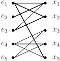
with , and . An edge belonging to is termed an s-arc. We also define important subgraphs of as , , and . For example, the bipartite representation of descriptor system (1) with (6) and in (7), and its subgraphs are illustrated in Fig. 2.

|

|

|


Furthermore, for a DM component of that has s-arcs [16], we call it a DM s-component, where is or . Let be DM components of , and are called consistent DM components; and are termed inconsistent DM components. The maximal consistent DM s-component is a consistent DM s-component of such that no other DM s-components are greater than related to the partial order . Note that there can be multiple maximal consistent DM s-components.
For instance, consider descriptor system (1) with parameters given in (6). The corresponding DM decomposition of the bipartite representation is depicted in Fig. 3. , , and are the consistent DM components of , and . That is, a maximal consistent DM s-component of this graph is , because there is no edge to enter from other DM components.
The following graph-theoretic characterization of structural controllability for descriptor system (1) is found in [19].
Proposition 2
Descriptor system (1) is structurally controllable if and only if
-
1.
,
-
2.
,
-
3.
No consistent DM components of contain s-arcs,
where is the size of a maximum matching of a bipartite graph .
Condition 1) represents the solvability of the system described in Eq. (2) in Section III, and the latter two conditions correspond to (3) in Proposition 1. From assumption (2), condition 1) in Proposition 2 is always satisfied. Assumption (2) also implies that there are no inconsistent DM components and of . This is because if we choose a maximum matching with a size of in , then and in Steps 3–4 in Algorithm 1 are both empty.
The following lemma describes the characterization of the consistent DM components of and .
Lemma 1
Proof
From assumption (2), condition 1) in Proposition 2 holds. This means that we can find the same maximum matching with size of in Step 1 of Algorithm 1 for and . Then, in Step 2 of Algorithm 1, of is a directed subgraph of of , as illustrated in Fig. 1. Also, , , . Thus, and in Steps 3 and 4 of Algorithm 1 coincide with and , respectively. That is, the node sets and of the inconsistent DM components in are as follows:
This implies that 1) and 2) are equivalent.
For instance, consider descriptor system (1) with (6) and in (7). The DM decomposition of the bipartite representation is depicted in Fig. 4. is the inconsistent DM component, is the consistent DM component, and . That is, is the maximal consistent DM s-component. Then, the consistent DM component in (Fig 3) is also consistent in (Fig. 4), since there is no directed path from to or in . Note that in general, there is a directed path from to , because edges in a matching are undirected.
Lemma 1 gives another characterization of the structural controllability condition for system (1) which satisfies solvability condition (2). This property will be used in the proof of Theorem 1 in the next subsection.
Corollary 1
Proof
From assumption (2), condition 1) in Proposition 2 holds. Condition 2’) is equivalent to condition 2) in Proposition 2. Also, condition 3) in Proposition 2 holds if and only if all nodes of consistent DM s-components in belong to an inconsistent DM s-component in , since consistent DM s-components contain s-arcs. Using Lemma 1, this is equivalent to the following:
-
3*)
For each consistent DM s-component in , which is a subgraph of , there is a directed path on from to .
This condition is also equivalent to 3’) in Corollary 1, since the non-maximal consistent DM components in have a directed path from the maximal consistent DM component in from the definition of the partial order .
Consider descriptor system (1) with and given in (6) and in (7) again. In , there is no directed path from to (Fig. 4). This means condition 3’) in Corollary 1 does not hold. Thus, descriptor system (1) with (6) and in (7) is not structurally controllable.
IV-A Existence of solution to Problem (4)
Unlike the traditional MCP0, it is not obvious whether or not an optimal solution exists for MCP0 with forbidden equations. By using Proposition 2 and Corollary 1, we obtain the following theorem which characterizes the existence of solutions to Problem (4). This theorem is employed to construct the optimal solution to Problem (4) in Section IV-D.
Theorem 1
Problem (4) has a solution if and only if both of the following conditions hold simultaneously:
-
a).
For each node set of maximal consistent DM s-components in , there exists such that .
-
b).
The graph-theoretic problem
(10) is feasible.
Proof
We assume that is a solution to Problem (4), and prove that conditions a) and b) hold. Note that this defines in (8). Suppose that a maximal consistent DM s-component of , which is a subgraph of , is not connected to , where denotes the set of input nodes. This means that there is no directed path on for from to in Step 2 of Algorithm 1. From Corollary 1, this implies that system (1) with the given is not structurally controllable, which contradicts the assumption. Thus, in , for the all node set of maximal consistent DM s-components , there exists an equation node which is connected to an input . This means that and condition a) holds. Moreover, condition 2) in Proposition 2 implies that the maximum matching of and exists. Then, is a matching in and contains since (Fig. 5). Thus, is a feasible solution to Problem (10), and condition b) holds.
Next, we assume that conditions a) and b) hold, and prove that Problem (4) has a solution. Consider the input nodes with a size of , where is the optimal solution to Problem (10). Then we can connect each equation node to an input node. This means that the edge set in (8) with size was constructed and forms a part of a matching of . That is, is a maximum matching of , and thus condition 2’) in Corollary 1 holds. Also, for each maximal consistent DM s-component of , we can connect an equation node to an input from condition a). That is, all maximal consistent DM s-components of have directed paths from the input node set . This means that condition 3’) in Corollary 1 holds. Thus, Problem (4) has a solution.
Theorem 1 implies that the existence of an optimal solution to MCP0 with forbidden equations for system (1) can be verified using pure graph theory.
For instance, consider descriptor system (1) with (6) depicted in Figs. 2 and 3.
-
1.
Consider the case . Then, MCP0 with is not feasible since condition b) in Theorem 1 does not hold. In fact, the maximal consistent DM s-component in has a node which does not belong to . This means that condition a) in Theorem 1 holds. However, since a set of nodes that connect to or is in in Fig. 2-(a), there is no matching of which satisfies . Thus, Problem (10) is not feasible.
-
2.
Consider the case . Then, MCP0 with is not feasible since condition a) does not hold. In fact, we can choose a feasible solution for Problem (10) as which satisfies . Thus, condition b) holds. However, a node of a maximal consistent DM s-component in is only and .
IV-B Optimal value for Problem (4)
Theorem 2
Proof
We assume that is an optimal solution with column size to Problem (4), and prove that , where by the definition. To this end, we assume . From condition 2) in Proposition 2, holds. Let be a maximum matching of . Then, is a feasible solution to Problem (10) and . Thus, we obtain . This contradicts the maximality of .
To prove that the equality holds, that is, (11) holds, we assume that is an optimal solution to Problem (10) such that , and construct a system that satisfies the constraints of Problem (4) as follows.
A system constructed by 1) and 2) satisfies condition I) of Problem (4). Moreover, a system constructed by 1) satisfies condition II), which is equivalent to that . This is because . Note that in 2), we can choose nodes so that condition II) is satisfied, because condition a) in Theorem 1 implies that all maximal consistent DM s-component has at least one node that is not in . Therefore, this system of the form (1) satisfies the constraints of Problem (4) and is given by (11).
IV-C Algorithm for Problem (10)
Algorithm 2 describes an algorithm for solving Problem (10) based on an alternating path algorithm [25]. Steps 1–4 check the feasibility of solving Problem (10). This is because if there is a feasible solution to Problem (10), by restricting the matching nodes in to , a matching of is obtained that satisfies (Fig. 6). The converse is shown to hold by the following alternating path algorithm in Steps 5–9, as shown in the proof of Theorem 3.

The alternating path algorithm that is used in Steps 5–9 is explained as follows: Let be a maximum matching of which does not satisfy the condition in (10). That is, is not a feasible solution to Problem (10). Note that can be computed by the Hopcraft-Karp algorithm [25]. Then, exists. Suppose a path
exists, which starts with and ends with . Then, a new maximum matching is defined by the symmetric difference between and . Moreover, the number of is just one less than the number of since . This procedure is illustrated in Fig. 7. By repeating this process, we can finally have a maximum matching of which satisfies . Note that from the construction of the alternating path, no paths that start at different vertices share edges with each other. This means that all desired alternating paths can be found by visiting each edge only once. Thus, we can execute Steps 6–9 by the breadth-first search algorithm with time complexity of [25].

Proof
Let be a maximum matching of . From the feasibility assumption of Problem (10), there exists a maximum matching of the bipartite graph by Steps 1–4 in Algorithm 2. Because of the construction of Algorithm 2, it is sufficient to show that there is an alternating path for each . In particular, we show that such alternates between edges of and . From the definition of , an edge exists that connects to . Also, there exists that . This is because otherwise is a matching, whose size is larger than and this contradicts the maximality of . Thus, there is a path with alternating the edges of and with a length of at least 2. To show that all alternating paths end with a node of , not of , suppose that an alternating path exists that ends with . We also assume that alternates between the edges of and . In this case, we have , since must start with and end with (Fig. 8). Thus, by replacing the edges with edges, we can obtain a matching larger than in size. This contradicts the maximality of . Thus, exists and is an alternating path. That is, connects . If , there is an edge that satisfies , and is a new alternating path between the edges of and . Thus, by inductively applying the above argument, we finally have an alternating path which ends with a node of .

To explain how Algorithm 2 works, consider Problem (10) with of descriptor system (6) and forbidden equations . We can choose in Step 1 of Algorithm 2 as . In Step 5, we have the maximum matching . Moreover, Step 6–9 illustrated in Fig. 9 produces the new maximum matching that satisfies in (10). In fact, we can find an alternating path and obtain the new matching .

IV-D Algorithm for Problem (4)
Theorem 4
Proof
Algorithm 3 is based on the argument in the proof of Theorem 2. Steps 1–4 determine whether or not Problem (4) is feasible, and Steps 1–3 are computed by Algorithm 1. Step 4 checks condition b) in Theorem 1 and output an optimal solution of Problem (10). Steps 5 and 6 in Algorithm 3 output the optimal solution to Problem (4), as shown in the proof of Theorem 2.
Next, we show that the time complexity is . Step 1–3 in Algorithm 3 can be checked by Algorithm 1, its time complexity is . The time complexity of Step 4 is . In fact, in Steps 1–5 in Algorithm 2 are computed by using the Hopcroft-Karp algorithm[25], the time complexity is . Moreover, Steps 6–9 in Algorithm 2 can be computed by breadth-first search algorithm in , as mentioned already. Steps 5–6 in Algorithm 3 can be computed in at most. Therefore, the time complexity of Algorithm 2 is .
Theorem 4 means that more general problems than those of [7, 16] can be solved with the same computational complexity. In fact, the problem addressed by [7] is a special case of Problem (4) with and , and it can be solved in . Moreover, the algorithm proposed in [16] deals with Problem (4) with , and the time complexity is .
To illustrate how Algorithm 3 works, consider descriptor system (1) with (6) and forbidden equations . In this case, Steps 1–4 determine that Problem (4) is feasible. In fact, the maximal consistent DM s-component in Fig. 3 has a node which does not belong to . Also, in Step 4, we obtain from the discussion of how Algorithm 2 works in IV-C. Thus, Problem (4) is feasible, since conditions a) and b) in Theorem 1 hold. Furthermore, Steps 5 and 6 produce
| (12) |
that is an optimal solution to Problem (4). In fact, from Theorem 2, we have the minimum number of inputs . Also, . Thus, connecting to , and to , we have as (12).
V Conclusion
In this study, we introduced the forbidden equations to MCP0 for structural descriptor systems. We gave a necessary and sufficient condition for the existence of solutions to the problem and provided the solution to MCP0. The algorithm for solving the problem can be computed in polynomial time as for the standard MCP0. That is, our proposed algorithm is well positioned for applications to large-scale descriptor systems.
In this paper, we focused on MCP0 for a structural descriptor system, since, for a structural descriptor system, MCP1 is NP-hard in general as shown in [16]. Thus, finding a solvable condition for MCP1 with forbidden equations in polynomial time would be a future project.
Furthermore, structural controllability considered in this paper requires that the system parameters be algebraically independent. This means that all non-zero system parameters are free, which may be a strong assumption for practical situations. To avoid this assumption, strong structural controllability has been proposed in [29], and studied from a graph-theoretic perspective in [30]. A strong structural controllability problem version in this paper is one of the future works.
Acknowledgment
This work was supported by the Japan Society for the Promotion of Science KAKENHI under Grant 20K14760 and 23K03899.
References
- [1] M. Mesbahi and M. Egerstedt, Graph theoretic methods in multiagent networks. Princeton University Press, 2010.
- [2] A. Rahmani, M. Ji, M. Mesbahi, and M. Egerstedt, “Controllability of multi-agent systems from a graph-theoretic perspective,” SIAM Journal on Control and Optimization, vol. 48, no. 1, pp. 162–186, 2009.
- [3] S. Gu, F. Pasqualetti, M. Cieslak, Q. K. Telesford, B. Y. Alfred, A. E. Kahn, J. D. Medaglia, J. M. Vettel, M. B. Miller, S. T. Grafton et al., “Controllability of structural brain networks,” Nature Communications, vol. 6, no. 1, pp. 1–10, 2015.
- [4] S. F. Muldoon, F. Pasqualetti, S. Gu, M. Cieslak, S. T. Grafton, J. M. Vettel, and D. S. Bassett, “Stimulation-based control of dynamic brain networks,” PLoS Computational Biology, vol. 12, no. 9, p. e1005076, 2016.
- [5] G. A. Pagani and M. Aiello, “The power grid as a complex network: a survey,” Physica A: Statistical Mechanics and its Applications, vol. 392, no. 11, pp. 2688–2700, 2013.
- [6] D.-S. Yang, Y.-H. Sun, B.-W. Zhou, X.-T. Gao, and H.-G. Zhang, “Critical nodes identification of complex power systems based on electric cactus structure,” IEEE Systems Journal, vol. 14, no. 3, pp. 4477–4488, 2020.
- [7] Y.-Y. Liu, J.-J. Slotine, and A.-L. Barabási, “Controllability of complex networks,” Nature, vol. 473, no. 7346, pp. 167–173, 2011.
- [8] F. Pasqualetti, S. Zampieri, and F. Bullo, “Controllability metrics, limitations and algorithms for complex networks,” IEEE Transactions on Control of Network Systems, vol. 1, no. 1, pp. 40–52, 2014.
- [9] T. H. Summers, F. L. Cortesi, and J. Lygeros, “On submodularity and controllability in complex dynamical networks,” IEEE Transactions on Control of Network Systems, vol. 3, no. 1, pp. 91–101, 2015.
- [10] A. Clark, B. Alomair, L. Bushnell, and R. Poovendran, “Submodularity in input node selection for networked linear systems: Efficient algorithms for performance and controllability,” IEEE Control Systems Magazine, vol. 37, no. 6, pp. 52–74, 2017.
- [11] L. Romao, K. Margellos, and A. Papachristodoulou, “Distributed actuator selection: Achieving optimality via a primal-dual algorithm,” IEEE Control Systems Letters, vol. 2, no. 4, pp. 779–784, 2018.
- [12] K. Sato and A. Takeda, “Controllability maximization of large-scale systems using projected gradient method,” IEEE Control Systems Letters, vol. 4, no. 4, pp. 821–826, 2020.
- [13] A. Olshevsky, “Minimal controllability problems,” IEEE Transactions on Control of Network Systems, vol. 1, no. 3, pp. 249–258, 2014.
- [14] S. Pequito, S. Kar, and A. P. Aguiar, “A framework for structural input/output and control configuration selection in large-scale systems,” IEEE Transactions on Automatic Control, vol. 61, no. 2, pp. 303–318, 2015.
- [15] A. Clark, B. Alomair, L. Bushnell, and R. Poovendran, “Input selection for performance and controllability of structured linear descriptor systems,” SIAM Journal on Control and Optimization, vol. 55, no. 1, pp. 457–485, 2017.
- [16] S. Terasaki and K. Sato, “Minimal controllability problems on linear structural descriptor systems,” IEEE Transactions on Automatic Control, vol. 67, no. 5, pp. 2522–2528, 2022.
- [17] C.-T. Lin, “Structural controllability,” IEEE Transactions on Automatic Control, vol. 19, no. 3, pp. 201–208, 1974.
- [18] L. Dai, Singular control systems. Springer, 1989.
- [19] K. Murota, Matrices and matroids for systems analysis. Springer Science & Business Media, 2009.
- [20] G.-R. Duan, Analysis and design of descriptor linear systems. Springer Science & Business Media, 2010.
- [21] Y.-Y. Liu and A.-L. Barabási, “Control principles of complex systems,” Reviews of Modern Physics, vol. 88, p. 035006, 2016.
- [22] G. Ramos, A. P. Aguiar, and S. Pequito, “An overview of structural systems theory,” Automatica, vol. 140, p. 110229, 2022.
- [23] K. Murota, “Structural controllability of a system in descriptor form expressed in terms of bipartite graphs (in japanese),” Transactions of the Society of Instrument and Control Engineers, vol. 20, no. 3, pp. 272–274, 1984.
- [24] K. J. Reinschke and G. Wiedemann, “Digraph characterization of structural controllability for linear descriptor systems,” Linear Algebra and its Applications, vol. 266, pp. 199–217, 1997.
- [25] B. Korte, J. Vygen, B. Korte, and J. Vygen, Combinatorial optimization. Springer, 2012, vol. 2.
- [26] E. Yip and R. Sincovec, “Solvability, controllability, and observability of continuous descriptor systems,” IEEE Transactions on Automatic Control, vol. 26, no. 3, pp. 702–707, 1981.
- [27] T. Berger and T. Reis, “Controllability of linear differential-algebraic systems—a survey,” in Surveys in differential-algebraic equations I. Springer, 2013, pp. 1–61.
- [28] T. Yamada and D. Luenberger, “Generic controllability theorems for descriptor systems,” IEEE Transactions on Automatic Control, vol. 30, no. 2, pp. 144–152, 1985.
- [29] H. Mayeda and T. Yamada, “Strong structural controllability,” SIAM Journal on Control and Optimization, vol. 17, no. 1, pp. 123–138, 1979.
- [30] J. Jia, H. J. Van Waarde, H. L. Trentelman, and M. K. Camlibel, “A unifying framework for strong structural controllability,” IEEE Transactions on Automatic Control, vol. 66, no. 1, pp. 391–398, 2021.