MIMO-OFDM-Based Massive Connectivity With Frequency Selectivity Compensation
Abstract
In this paper, we study how to efficiently and reliably detect active devices and estimate their channels in a multiple-input multiple-output (MIMO) orthogonal frequency-division multiplexing (OFDM) based grant-free non-orthogonal multiple access (NOMA) system to enable massive machine-type communications (mMTC). First, by exploiting the correlation of the channel frequency responses in narrow-band mMTC, we propose a block-wise linear channel model. Specifically, the continuous OFDM subcarriers in the narrow-band are divided into several sub-blocks and a linear function with only two variables (mean and slope) is used to approximate the frequency-selective channel in each sub-block. This significantly reduces the number of variables to be determined in channel estimation and the sub-block number can be adjusted to reliably compensate the channel frequency-selectivity. Second, we formulate the joint active device detection and channel estimation in the block-wise linear system as a Bayesian inference problem. By exploiting the block-sparsity of the channel matrix, we develop an efficient turbo message passing (Turbo-MP) algorithm to resolve the Bayesian inference problem with near-linear complexity. We further incorporate machine learning approaches into Turbo-MP to learn unknown prior parameters. Numerical results demonstrate the superior performance of the proposed algorithm over state-of-the-art algorithms.
Index Terms:
grant-free non-orthogonal multiple access, orthogonal frequency division multiplexing, turbo message passing.I Introduction
massive machine-type communications (mMTC) has been envisioned as one of the three key application scenarios of fifth-generation (5G) wireless communications. To support massive connectivity of machine-type devices, mMTC typically has the feature of sporadic transmission with short packets, which is different from conventional human-type communications [1]. This implies that only a small subgroup of devices are active in any time instance of mMTC. As such, in addition to channel estimation and signal detection, a fundamentally new challenge for the design of an mMTC receiver is to reliably and efficiently identify which subgroup of devices are actively engaged in packet transmission.
Recently, a new random access protocol termed grant-free non-orthogonal multiple access (NOMA) has been evaluated and highlighted for mMTC [2]. In specific, in grant-free NOMA, the devices share the same time and frequency resources for signal transmission, and the signals can be transmitted without the scheduling grant from the base station (BS). The receiver at the BS is then required to perform active device detection (ADD), channel estimation (CE), and signal detection (SD), either separately or jointly. The earlier work [3, 4, 5, 6] assumed that full channel state information (CSI) can be acquired at the BS and studied joint CE and SD. However, the assumption of full CSI availability is not practical since it will cause a huge overhead to estimate the CSI of all access devices. The follow-up work [7] proposed to divide the process at the BS into two phases, namely, the joint ADD and CE phase the SD phase. Since the BS only needs to estimate the CSI of active devices, the pilot overhead is significantly reduced. In addition, the channel sparsity in the device domain enables the employment of compressed sensing (CS) algorithms [8] to solve the joint ADD and CE problem. For example, the authors in [9] considered the multiple-input multiple-output (MIMO) transmission and leveraged a multiple measurement vector (MMV) CS technique termed vector approximate message passing (Vector AMP) [10] to achieve asymptotically perfect ADD. In [11], the authors further considered a mixed analog-to-digital converters (ADCs) architecture at the BS antennas and proposed a CS algorithm based on the turbo compressive sensing (Turbo-CS) [12]. It is known from [12] that Turbo-CS outperforms approximate message passing (AMP) [13] both in convergence performance and computational complexity. Another line of research considered the more challenging joint ADD, CE, and SD problem [14, 15]. As compared to the two-phase approach, these joint schemes can achieve significant performance improvement but at the expense of higher computational complexity.
Orthogonal frequency division multiplexing (OFDM) is a mature and enabling technology for 5G to provide high spectral efficiency. As such, the design of OFDM-based grant-free NOMA has attracted much research interest in recent years [16, 17, 18]. In [16], the authors exploited the block-sparsity of the channel responses on OFDM subcarriers to design a message-passing-based iterative algorithm. Besides, it has been demonstrated in [17] that the message-passing-based iterative algorithm can be unfolded into a deep neural network. By training the parameters of the neural network, the convergence and performance of the algorithm are improved. Furthermore, OFDM-based grant-free NOMA with massive MIMO has been considered in [18]. By leveraging the sparsity both in the device domain and the virtual angular domain, the authors utilized the AMP algorithm to achieve the joint ADD and CE. One issue in [16, 17, 18] is that the frequency-domain channel estimation on every subcarrier requires a high pilot overhead, which is inefficient for the short data packets transmission in mMTC.
To reduce the pilot overhead, a common strategy is to transform the frequency-domain channel into the time-domain channel by inverse discrete Fourier transform (IDFT) [19]. Due to the limited delay spread in the time-domain channel, the time-domain channel is sparse, thereby requiring fewer pilots for CE. Furthermore, by exploiting the sparsity of both the time-domain channel and the device activity pattern, some state-of-the-art CS algorithms such as Turbo-CS [12, 20] and Vector AMP [10, 9] can be applied to the considered systems with some straightforward modifications. However, there exists an energy leakage problem caused by the IDFT transform to obtain the time-domain channel. The energy leakage compromises the channel sparsity in the time domain. In addition, the power delay profile (PDP) is generally difficult for the BS to acquire, and thus cannot be exploited as prior information to improve the system performance.
Motivated by the bottleneck of the existing channel models when applied to the MIMO-OFDM-based grant-free NOMA system, we aim to construct a channel model to enable efficient massive random access. Due to the short packets in mMTC, the bandwidth for packet transmission is usually narrow, e.g., 1MHz for access devices [21]. Then the variations of the channel frequency responses across the subcarriers are limited and slow. By leveraging this fact, we propose a block-wise linear channel model. Specifically, the continuous subcarriers are divided into several sub-blocks. In each sub-block, the frequency-selective channel is approximated by a linear function. We demonstrate that the number of variables in the block-wise linear channel model is typically much less than the number of non-zero delay taps in the time-domain channel. Moreover, the sub-block number can be modified to strike the trade-off between the model accuracy and the number of the channel variables to be estimated.
Based on the block-wise linear system model, we aim to design a CS algorithm to solve the joint ADD and CE problem. We first introduce a probability model to characterize the block-sparsity of the channel matrix. Then the joint ADD and CE is formulated as a Bayesian inference problem. Inspired by the success of Turbo-CS [12, 20] in sparse signal recovery, we design a message passing algorithm termed turbo message passing (Turbo-MP) to resolve the Bayesian inference problem. The message passing processes are derived based on the principle of Turbo-CS and the sum-product rule [22]. By designing a partial orthogonal pilot matrix with fast transform, Turbo-MP achieves near-linear complexity.
Furthermore, we show that machine learning methods can be incorporated into Turbo-MP to learn the unknown prior parameters. We adopt the expectation maximization (EM) algorithm [23] to learn the prior parameters. We then show how to unfold Turbo-MP into a neural network (NN), where the prior parameters are seen as the learnable parameters of the neural network. Numerical results show that NN-based Turbo-MP has a faster convergence rate than EM-based Turbo-MP. More importantly, we show that Turbo-MP designed for the propose frequency-domain block-wise linear model significantly outperforms the state-of-the-art counterparts, especially those message passing algorithms designed for the time-domain sparse channel model [9, 11].
I-A Notation and Organization
We use bold capital letters like for matrices and bold lowercase letters for vectors. and are used to denote the transpose and the conjugate transpose, respectively. We use for the diagonal matrix created from vector , for the block diagonal matrix with the -th block being vector , and for the block diagonal matrix with the -th block being matrix . We use for the vectorization of matrix and for the Kronecker product. and are used to denote the Frobenius norm of matrix and the norm of vector , respectively. Matrix denotes the identity matrix with an appropriate size. For a random vector , we denote its probability density function (pdf) by . denotes the Dirac delta function and denotes the Kronecker delta function. The pdf of a complex Gaussian random vector with mean and covariance is denoted by .
The remainder of this paper is organized as follows. In Section II, we introduce the existing system models. Furthermore, we propose the block-wise linear system model and demonstrate its superiority. In Section III, we formulate a Bayesian inference problem to address the ADD and CE problem. In Section IV, we propose the Turbo-MP algorithm, describe the pilot design, and analyze the algorithm complexity. In Section V, we apply the EM algorithm to learn the prior parameters. Moreover, we show how Turbo-MP is unfolded into a neural network. In Section VI, we present the numerical results. In Section VII, we conclude this paper.
II System Modeling
II-A MIMO-OFDM-Based Grant-free NOMA Model
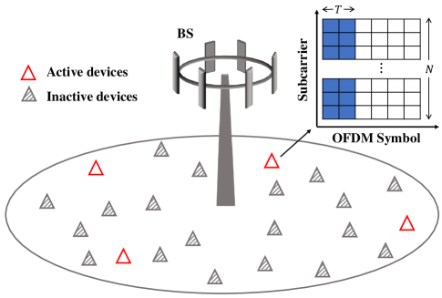
Consider a MIMO-OFDM-based grant-free NOMA system as shown in Fig. 1, where a frequency band of adjacent OFDM subcarriers are allocated for mMTC. is usually much less than the total number of available subcarriers in the considered OFDM system. This frequency allocation strategy follows the idea of narrow-band internet-of-things [24] and network slicing [25]. Then the allocated bandwidth is used to support single-antenna devices to randomly access an -antenna base station (BS). In each time instance, only a small subset of devices are active. To characterize such sporadic transmission, the device activity is described by an indicator function as
| (1) |
with where .
We adopt a multipath block-fading channel, i.e., the multipath channel response remain constant within the coherence time. Denote the channel frequency response on the -th subcarrier from the -th device at -th BS antenna by
| (2) |
where is the OFDM subcarrier spacing; is the number of channel taps of the -th device; and 111Strictly speaking, the differences of the tap delay at different BS antennas are absorbed in are respectively the -th tap power and tap delay of the -th device; is the normalized complex gain and assumed to be independent for any [26]. Then the channel frequency response can be expressed in a matrix form as
| (6) |
Let be the pilot symbol of the -th device transmitted on th -th subcarrier at the -th OFDM symbol, and be the number of OFDM symbols for pilot transmission. Then we construct a block diagonal matrix with the -th diagonal block being , i.e.,
| (7) |
Assume the cyclic-prefix (CP) length . After removing the CP and applying the discrete Fourier transform (DFT), the system model in the frequency domain is described as
| (8) |
where is the observation matrix; is an additive white Gaussian noise (AWGN) matrix with its elements independently drawn from . In [16, 17, 18], CS algorithms were proposed based on (8) to achieve the CE on every OFDM subcarrier.
Define the time-domain channel matrix of the -th device as . Note that can be represented as the IDFT of , i.e,
| (9) |
where is the DFT matrix with the -th element being . Similarly, is represented as . Substituting into (8), we obtain
| (10) |
where is the channel matrix in the time domain. It is known that the channel delay spread is usually much smaller than , i.e., some rows of are zeros. Besides, due to the sporadic transmission of the devices, is an all-zero matrix if device is inactive. In this case, CS algorithms such as Vector AMP [10, 9] and Turbo-CS [12, 20] can be used to recover from observation by exploiting the sparsity of . However, path delay is generally not an integer multiple of the sampling interval, resulting in the energy leakage problem of the IDFT transform (9) which severely compromises the sparsity of . An illustration of the energy leakage problem is given in Fig. 2(b).

II-B Proposed Block-Wise Linear System Model
For narrow-band mMTC [1], the variations of the channel frequency response across the subcarriers are typically slow and limited, which inspires us to develop an alternative channel model to efficiently leverage the correlation in the frequency domain. In specific, we propose a block-wise linear channel model. We divide the continuous subcarriers into sub-blocks. In each sub-block , a linear function is used as the approximation of the channel frequency response:
| (11) |
where and represent the mean and slope of the linear function in the -th sub-block, respectively; is the error term due to model mismatch; and is the midpoint of . Intuitively, can be seen as the mean-value of the channel response in the -th sub-block, and is used to characterize the change of the channel response for the compensation of the frequency-selectivity. For the -th device, we define the matrix and as
| (15) | ||||
| (19) |
The reason for introducing in (15)-(19) is that the channel estimation and device activity detection can be jointly achieved by recovering and .
Define with being an all-one vector of length and with . Then the block-wise linear approximation of the channel frequency response is given by
| (20) |
where is the error matrix from the -th device with the -th element in (II-B). Substituting (20) into (8) with some manipulations, we obtain the block-wise linear system model as
| (21) |
where and are the pilot matrices; is the channel mean matrix; is the channel compensation matrix; is the summation of the AWGN and the error terms from model mismatch as
| (22) |
Following the central limit theorem, for a large devices number , can be modeled as an AWGN matrix with mean zero and variance . We note that with and , system model (21) reduces to the model (8) in [16, 17, 18] where the channel response on every subcarrier needs to be estimated exactly. Furthermore, we adjust the sub-block number to strike a balance between the number of channel variables to be estimated and the model accuracy. An example is shown in Fig. 2 where the channel response in the frequency domain and its block-wise linear approximation is given in Fig. 2(a). It is seen that sub-block number is sufficient to ensure that the block-wise linear model approximates the frequency-domain channel response very well. This implies that, with model (21), only variables need to be estimated for each device at each BS antenna. Compared to the channel response in the time domain as shown in Fig. 2(b), it is clear that the number of unknown variables is much less than the number of corresponding non-zero taps. In the remainder of the paper, we focus on the estimation algorithm design based on model (21). In the simulation section, we will show that our algorithm designed based on (21) significantly outperforms the existing approaches based on (8) and (II-A).
III Problem Statement
With model (21), our goal is to recover the channel mean matrix and channel compensation matrix based on the noisy observation . This task can be constructed as a Bayesian inference problem. In the following, we first introduce the probability model of and , and then describe the statistical inference problem.
Due to the sporadic transmission of the devices, matrices and have a structured sparsity referred to as block-sparsity. In specific, if the -th device is inactive, we have and . With some abuse of notation, we utilize a conditional Bernoulli-Gaussian (BG) distribution [19] to characterize the block-sparsity as
| (23) |
where is the Dirac delta function and is the Kronecker delta function. With indicator function , and are both zeros. With , the elements of and are independent and identically distributed (i.i.d.) Gaussian with variances and , respectively. We further assume that each device accesses the BS in an i.i.d. manner. Then the indicator function is drawn from the Bernoulli distribution as
| (24) |
where is the device activity rate.
Consider an estimator to minimize the mean-square error (MSE) of and . It is known that the estimator which minimizes the MSE is the posterior expectation with respect to the posterior distribution [28]. Define and as the -th column of and , respectively. Define as the -th column of . Then the posterior distribution is described as
| (25) |
where and are the likelihood and the prior, respectively; vector . In mMTC with a large device number , it is computationally intractable to obtain the minimum mean-square error (MMSE) estimator. In the following section, we propose a low-complexity algorithm termed turbo message passing (Turbo-MP) to obtain an approximate MMSE solution.
IV Turbo Message Passing
IV-A Algorithm Framework

The factor graph representation of is shown in Fig. 3, based on which Turbo-MP is established. In the factor graph, the likelihood and prior as in (III) are treated as the factor nodes (grey rectangles), while the random variables are treated as the variable nodes (blank circles). In specific, Turbo-MP consists of four modules referred to as Module A, B, C, and D, respectively. Module A is to obtain the estimates of the channel mean matrix and the channel compensation matrix by exploiting the likelihood . Modules B and C are to obtain the estimates of and by exploiting the priors and , respectively. Module D is to obtain the estimate of by exploiting the prior . The estimates are passed between modules in each Turbo-MP iteration like turbo decoding [29]. For example, the output of Module B is used as the input of Module A, and vice versa. The four modules are executed iteratively until convergence. The derivation of Turbo-MP algorithm follows the sum-product rule [22] and the principle of Turbo-CS [12, 20].
IV-B Module A: Linear Estimation of and
In Module A, and at antenna are estimated separately by exploiting the likelihood and the messages from Modules B and C. In specific, denote the message from variable node to factor node by and the message from variable node to factor node by . Following the principle of Turbo-CS [12, 20], we assume that the above two messages are Gaussian, i.e., and . Note that the algorithm starts with , , , and . From the sum-product rule, the belief of at factor node is
| (26) |
In the above, is the subscript is the shorthand for factor node ; denotes the set includes all elements in except . Then we define the belief of at factor node as
| (27) |
Combing (IV-B) and (27), the message is also Gaussian with the mean and variance . From [20, Eq. 11], the mean is expressed as
| (28) |
where is the covariance matrix given by
| (29) |
To reduce the computational complexity of channel inverse , we require that is partial orthogonal [12], i.e., , where is the average power of the pilot symbol. (The design of to guarantee partial orthogonality is presented in IV-F.) In addition, it is easy to verify where the diagonal matrix with being an all-one vector of length . Then the expression of is simplified to
| (30) |
Then the variance is given by
| (31) |
where is the -th element of . We note that (IV-B) and (31) also corresponds to the linear minimum mean-square error (LMMSE) estimator [28, Chap. 11] given the observation , the mean and the variance .
From the sum-produce rule, the extrinsic message from factor node to variable node is calculated as
| (32) |
Given the Gaussian messages and , the extrinsic message is also Gaussian as
| (33) |
where the variance and the mean are respectively given by
| (34) |
The calculation to obtain the belief of is similar. We have the Gaussian belief with its mean and variance respectively given by
| (35) |
where is the -th element of . Then we obtain the extrinsic message with its mean and variance as follows:
| (36) |
IV-C Module B: Denoiser of
In Module B, each is estimated individually by exploiting the prior and the messages from Modules A and D. In specific, given the message from module A, we have
| (37) |
For description convenience, the factor node is replaced by . Then the message from variable node to factor node is expressed as
| (38) |
where with the -th element and with being an all-one vector of length .
Combing the Bernoulli Gaussian prior , Gaussian message and Bernoulli message in (IV-E), the belief of at factor node is Bernoulli Gaussian and expressed as
| (39) |
where
| (40) |
We note that the mean of with respect to is
| (41) |
Define . The variance of the -th element of with respect to is
| (42) |
Recall that the relationship between and is described as . Through such relationship, we obtain . Following [12, 20], the variance is approximated by
| (43) |
Then the belief of at Module B is defined as
| (44) |
The above Gaussian belief assumption is widely used in message passing based iterative algorithms such as Turbo-CS [12], approximate message passing (AMP) [13] and expectation propagation (EP) [30]. Such treatment may loses some information but facilities the message updates. (Strictly speaking, the belief of the variable corresponds to a factor node instead of a Module. However, the belief of is associated with factor nodes , making the expression cumbersome. For convenience, we use the definition .)
From the sum-product rule, we have . Then the extrinsic message is calculated as
| (45) |
Given the Gaussian messages and , the extrinsic message is also Gaussian with its variance and mean respectively given by
| (46) |
where and are respectively used as the input mean and variance of for Module A, i.e., and . Then we have
| (47) |
IV-D Module C: Denoiser of
Similarly to the process in Module B, each in module C is estimated individually by exploiting the prior and the messages from Modules A and D. For description convenience, is used to replace factor node . The message from variable node to factor node is expressed as
| (48) |
where with its -th element and .
With the Bernoulli Gaussian prior , Gaussian message and message in (IV-E), the belief of at factor node is Bernoulli Gaussian and expressed as
| (49) |
where
| (50) |
Then the mean of with respect to is
| (51) |
The variance of the -th element of is given by
| (52) |
Similarly to (44), we define the belief of at Module C as
| (53) |
with the variance given by
| (54) |
Then we calculate the Gaussian extrinsic message with its variance and mean as follows :
| (55) |
The input mean and variance of for module A are respectively set as and .
IV-E Module D: Estimation of
In Module D, we calculate the messages and as the inputs of Modules B and C, respectively. Furthermore, the device activity is detected by combing the messages from Modules B and C. According to the sum-product rule, the message from factor node to variable node is
| (56) |
where
| (57) |
Then the message from variable node to factor node is
| (58) |
with
| (59) |
Similarly to (IV-E), the message from factor node to variable node is
| (60) |
where
| (61) |
Then the message from variable node to factor node is
| (62) |
with
| (63) |
Define the belief of at factor node as . From the sum-product rule, is given by
| (64) |
where
| (65) |
Clearly, () indicates the probability that the -th device is active. Therefore, we adopt a threshold-based strategy for device activity detection as
| (66) |
where is a predetermined threshold.
IV-F Pilot Design and Complexity Analysis
The overall algorithm is summarized in Algorithm 1. In each iteration, the channel mean matrix is first updated (step 2-8) and then the channel compensation matrix is updated (step 9-15). This is because the power of the channel mean matrix is dominant and the iteration process effectively suppresses error propagation. Note that the prior parameters learning is shown in the next section.
As mentioned in Section IV-B, the pilot matrix is required to be partial orthogonal. To fulfill this requirement, the pilot symbols transmitted on the -th subcarrier at the -th OFDM symbol has the following property:
| (67) |
where is a row vector randomly selected from an orthogonal matrix and the selected row is different for different . Combing and the definition of in (7), it is easy to verify the partial orthogonality of .
We next show that when is the discrete Fourier transform (DFT) matrix, the algorithm complexity can be further reduced. To enable the fast Fourier transform (FFT), the pilot matrix is expressed as
| (68) |
where is a row selection matrix consisting of randomly selected rows from the identity matrix. (The selected rows are different for different .) is a column exchange matrix. In specific, in the -th column of , only the -th row is one while the others are zeros. Note that and matrix has the same fast transform as due to the relationship .
By using the FFT, the estimates of and in Module A has the complexity . In modules B, C and D, the estimates of , , and involve vector multiplications with the complexity . As a result, the overall complexity of Turbo-MP is per iteration. It is worth noting that the algorithm complexity is linear to the antenna number and is approximately linear to the device number .
V Parameters Learning
The prior parameters used in Turbo-MP are unknown and required to be estimated in practice. In the following, we utilize two machine learning methods, i.e., the EM and the NN approach, to learn these prior parameters.
V-A EM Approach
We first use the EM algorithm [23] to learn . The EM process is described as
| (69) |
where is the estimate of at the -th EM iteration. represents the expectation over the posterior distribution . Note that it is difficult to obtain the true posterior distribution. Instead, we utilize the message products as an approximation. Then we set the derivatives of (with respect to ) to zero and obtain
| (70) |
Similarly, the EM estimate of is given by
| (71) |
The EM estimate of is given by
| (72) |
The EM estimate of is given by
| (73) |
Turbo-MP algorithm with EM approach to learn is shown in Algorithm 1, which we refer to as Turbo-MP-EM. In practice, we can update several times and then update once to improve the algorithm stability. Besides, it is known the estimation accuracy of , , and by EM relies on the accuracy of the posterior approximation in Turbo-MP, and inaccurate estimation may affect the algorithm convergence. Therefore, we recommend to update , , and once after and is updated several times. In the first algorithm iteration, we initialize , , and . As for the update of , it is updated in each iteration of Turbo-MP with the initialization . However, we find the second part of (V-A), i.e., is negligible in most cases while in worst case, it continues to rise with the increase of Turbo-MP iterations. Therefore, we delete the second part of (V-A) in simulation.
V-B NN Approach
In deep learning [3], training data can be used to train the parameters of a deep neural network. Inspired by the idea in [31] and [32], we unfold the iterations of Turbo-MP algorithm and regard it as a feed-forward NN termed Turbo-MP-NN. In specific, each iteration represents one layer of the feed-forward NN where is seen as the network parameter. We hope that with an appropriately defined loss function, Turbo-MP-NN can adaptively learn from the training data.

The structure of Turbo-MP-NN is shown in Fig. 4 which consists of layers. Each layer has the same structure, i.e., the same linear and non-linear operations following step 2-15 in algorithm 1. To distinguish the estimates at different layer, denote , and obtained at the -th layer (iteration) by , , and , respectively. In the -th layer, the inputs consist of training data and the outputs of the -th layer including , , and . The loss function is defined as the normalized mean square error (NMSE) of channel estimation given by
| (74) |
where the estimates and can be and or and obtained in the -th layer. Note that different from the EM approach, all layers of the NN have the same . To avoid over-fitting, we train the neural network through the layer-by-layer method [32]. Specifically, we begins from the training of the first layer, then first two layers, and finally layers. is initialized following (63). For the first layers , we optimize by using the back-propagation to minimize the loss function
| (75) |
The detailed training process is shown in Algorithm 2. Once trained, the iteration process of Turbo-MP-NN is illustrated in Algorithm 1. From the simulation, we find that for a fixed sub-block number , the change of the learned and is linear with respect to the signal-to-ratio , and the change of the minus is also linear with respect to the SNR. As such, there is no need to train the prior parameters offline at different SNR.
VI Numerical Results
In this section, we evaluate the performance of the proposed Turbo-MP algorithm in channel estimation and device activity detection. The simulation setup is as follows. The BS is equipped with or antennas. OFDM subcarriers are allocated for the random access with subcarrier spacing kHz. devices access the BS and transmit their signals with probability in each timeslot. We adopt the TDL-C channel model with 300 ns r.m.s delay spread and its detailed PDP can be found in TR 38.901 R14 [27]. For Turbo-MP-NN, we randomly generate channel realizations for training and the training data is divided into minibatches of size 4. To evaluate the performance of the proposed algorithm, we use the NMSE and the detection error probability as the performance metrics, where is the probability of miss detection and is the probability of false alarm. Note that for the figures showing CE performance, each data point is averaged over realizations. For the figures showing ADD performance, at each data point, the accumulative number of the detection errors is larger than .
The baseline algorithms are as follows:
-
•
FD-GMMV-AMP: The GMMV-AMP algorithm was proposed in [18] to joint estimate the channel response on every subcarrier and detect the active devices based on the frequency-domain system model (8). We assume that the prior parameters including the channel variance on every subcarrier, noise variance and access probability are known for FD-GMMV-AMP. (The following algorithms also use and as known parameters.)
-
•
TD-Gturbo-MMV: We adopt the Gturbo-MMV algorithm [11] to achieve the ADD and CE based on the time-domain system model (II-A), which we refer to as TD-Gturbo-MMV. Note that the denoiser in [11] is extended and applied to . We further assume that the BS knows the delay spread of the time-domain channel, and thus the time-domain delay taps can be truncated to reduce the number of channel coefficients to be estimated. Specifically, there are delay taps left with taps at the head and taps at the tail which contains energy of the time-domain channel. As a Bayesian algorithm, TD-Gturbo-MMV requires the PDP of the time-domain channel as prior information. One option is to assume that the exact PDP is known. However, in practice, the exact PDP of each device is difficult to acquire. Therefore, we also consider using a flat PDP with equal-power delay taps as the prior information.
- •

Fig. 5 shows the channel estimation NMSE versus the iteration number. Both Turbo-MP-EM and Turbo-MP-NN converge and significantly outperform the other algorithms by more than dB in CE NMSE. Turbo-MP-NN converges faster than Turbo-MP-EM, which implying that the neural network approach can obtain more accurate prior parameters. In addition, it is seen that FD-GMMV-AMP has a quite poor performance since the average number of the unknown variables on every subcarrier is much larger than the number of the measurements, i.e., . Concerning TD-GTurbo-MMV and TD-Vector AMP, there is a performance loss when the PDP is not exactly known.


To further demonstrate the performance superiority of Turbo-MP, Fig. 6 shows the channel estimation NMSE against the SNR. With the increase of the SNR, the performance gap between Turbo-MP and the baselines becomes larger, which suggests that if the BS adopts the Turbo-MP algorithm to reach a high CE performance, the devices will consume much lower power. It is also found that the CE performance of each algorithm at different BS antenna number is similar. Fig. 7 shows the detection error probability versus the SNR. It is seen that as the antenna number increases, the detection performances of the tested algorithms improve more than one order of magnitude. This is because the increase of BS antennas leads to a larger dimension of the block-sparsity vector. Among the tested algorithms, Turbo-MP-NN has superiority over the other algorithms especially when antenna number .


Fig. 8 shows the channel estimation NMSE against the different number of OFDM symbols. There is a clear performance gap between Turbo-MP and the baselines at different . Moreover, to reach dB, the pilot overhead () for Turbo-MP is only half of that () for TD-Vector AMP and TD-Gturbo-MMV with exact PDP. It is shown that our proposed scheme can support mMTC with a dramatically reduced overhead. In Fig. 9, the detection error probability versus OFDM symbols is shown. The trend is similar to Fig. 7. Turbo-MP achieves the best ADD performance at the different number of OFDM symbols.


Fig. 10 illustrates the impact of the sub-block number on the CE performance at different SNR, which implies the trade-off between the estimation accuracy and the model accuracy. In specific, it is seen that at low SNR, a smaller sub-block number corresponds to better NMSE performance while the case is contrary at high SNR. The reason is that the NMSE performance is mainly affected by AWGN at low SNR, in which case a small sub-block number helps to improve the estimation accuracy. However, at high SNR, the CE performance is limited by the model mismatch which can be reduced by increasing the sub-block number. In practice, a proper sub-block number needs to be chosen according to the wireless environment. Fig. 11 shows the miss detection probability versus false alarm probability, where we modify the threshold to reach the trade-off between miss detection and false alarm. Clearly, Turbo-MP-NN outperforms Turbo-MP-EM at different settings of sub-block number and antennas number. Besides, we see that Turbo-MP with the smaller sub-block number corresponds to a better ADD performance at dB. This result is consistent with the CE performance in Fig. 10. From Fig. 10 and Fig.11, we find that the algorithms can achieve excellent device detection performance at relative low SNR while the accurate channel estimation requires a higher SNR. Such observation suggests that when the BS is equipped with multiple antennas, the bottleneck in mMTC is CE instead of ADD.
VII Conclusion
In this paper, a frequency-domain block-wise linear channel model was established in the MIMO-OFDM-based grant-free NOMA system to effectively compensate the channel frequency-selectivity and reduce the number with a small number of variables to be determined in channel estimation. From the perspective of Bayesian inference, we designed the low-complexity Turbo-MP algorithm to solve the ADD and CE problem, where machine learning was incorporated to learn the prior parameters. We numerically show that Turbo-MP designed for the proposed block-wise linear model significantly outperforms the state-of-the-art counterpart algorithms.
References
- [1] C. Bockelmann, N. Pratas, H. Nikopour, K. Au, T. Svensson, C. Stefanovic, P. Popovski, and A. Dekorsy, “Massive machine-type communications in 5g: physical and mac-layer solutions,” IEEE Commun. Mag., vol. 54, no. 9, pp. 59–65, Sep. 2016.
- [2] Study on New Radio Access Technology, Std. TR 38.901 version 14.2.0 Release 14, 3GPP, Sep. 2017.
- [3] B. Wang, L. Dai, Y. Zhang, T. Mir, and J. Li, “Dynamic compressive sensing-based multi-user detection for uplink grant-free noma,” IEEE Commun. Lett., vol. 20, no. 11, pp. 2320–2323, Nov. 2016.
- [4] Y. Du, C. Cheng, B. Dong, Z. Chen, X. Wang, J. Fang, and S. Li, “Block-sparsity-based multiuser detection for uplink grant-free NOMA,” IEEE Trans. Wireless Commun., vol. 17, no. 12, pp. 7894–7909, Dec. 2018.
- [5] B. K. Jeong, B. Shim, and K. B. Lee, “MAP-based active user and data detection for massive machine-type communications,” IEEE Trans. Veh. Technol., vol. 67, no. 9, pp. 8481–8494, Sep. 2018.
- [6] L. Liu, C. Yuen, Y. L. Guan, Y. Li, and C. Huang, “Gaussian message passing for overloaded massive MIMO-NOMA,” IEEE Trans. Wireless Commun., vol. 18, no. 1, pp. 210–226, Jan. 2018.
- [7] L. Liu, E. G. Larsson, W. Yu, P. Popovski, C. Stefanovic, and E. de Carvalho, “Sparse signal processing for grant-free massive connectivity: A future paradigm for random access protocols in the internet of things,” IEEE Signal Process. Mag, vol. 35, no. 5, pp. 88–99, Sep. 2018.
- [8] D. L. Donoho, “Compressed sensing,” IEEE Trans. Inf. Theory, vol. 52, no. 4, pp. 1289–1306, April 2006.
- [9] L. Liu and W. Yu, “Massive connectivity with massive MIMO-part I: Device activity detection and channel estimation,” IEEE Trans. Signal Process., vol. 66, no. 11, pp. 2933–2946, June 2018.
- [10] Z. Chen, F. Sohrabi, and W. Yu, “Sparse activity detection for massive connectivity,” IEEE Transactions on Signal Processing, vol. 66, no. 7, pp. 1890–1904, April 2018.
- [11] T. Liu, S. Jin, C. Wen, M. Matthaiou, and X. You, “Generalized channel estimation and user detection for massive connectivity with mixed-ADC massive MIMO,” IEEE Trans. Wireless Commun., vol. 18, no. 6, pp. 3236–3250, June 2019.
- [12] J. Ma, X. Yuan, and L. Ping, “Turbo compressed sensing with partial DFT sensing matrix,” IEEE Signal Process. Lett., vol. 22, no. 2, pp. 158–161, Feb. 2015.
- [13] M. Bayati and A. Montanari, “The dynamics of message passing on dense graphs, with applications to compressed sensing,” IEEE Trans. Inf. Theory, vol. 57, no. 2, pp. 764–785, Feb. 2011.
- [14] Q. Zou, H. Zhang, D. Cai, and H. Yang, “A low-complexity joint user activity, channel and data estimation for grant-free massive MIMO systems,” IEEE Signal Process. Lett., vol. 27, pp. 1290–1294, July 2020.
- [15] T. Ding, X. Yuan, and S. C. Liew, “Sparsity learning-based multiuser detection in grant-free massive-device multiple access,” IEEE Trans. Wireless Commun., vol. 18, no. 7, pp. 3569–3582, July 2019.
- [16] Y. Zhang, Q. Guo, Z. Wang, J. Xi, and N. Wu, “Block sparse bayesian learning based joint user activity detection and channel estimation for grant-free NOMA systems,” IEEE Trans. Veh. Technol., vol. 67, no. 10, pp. 9631–9640, Oct. 2018.
- [17] Z. Zhang, Y. Li, C. Huang, Q. Guo, C. Yuen, and Y. L. Guan, “DNN-aided block sparse Bayesian learning for user activity detection and channel estimation in grant-free non-orthogonal random access,” IEEE Trans. Veh. Technol., vol. 68, no. 12, pp. 12 000–12 012, Dec. 2019.
- [18] M. Ke, Z. Gao, Y. Wu, X. Gao, and R. Schober, “Compressive sensing-based adaptive active user detection and channel estimation: Massive access meets massive MIMO,” IEEE Trans. Signal Process., vol. 68, pp. 764–779, Jan 2020.
- [19] X. Kuai, L. Chen, X. Yuan, and A. Liu, “Structured turbo compressed sensing for downlink massive mimo-ofdm channel estimation,” IEEE Trans. Wireless Commun., vol. 18, no. 8, pp. 3813–3826, Aug. 2019.
- [20] Z. Xue, X. Yuan, and Y. Yang, “Denoising-based turbo message passing for compressed video background subtraction,” IEEE Trans. Image Process., vol. 30, pp. 2682–2696, Feb. 2021.
- [21] R. Ratasuk, N. Mangalvedhe, D. Bhatoolaul, and A. Ghosh, “LTE-M evolution towards 5G massive MTC,” in in proc. 2017 IEEE Globecom Workshops (GC Wkshps), 2017, pp. 1–6.
- [22] F. R. Kschischang, B. J. Frey, and H. . Loeliger, “Factor graphs and the sum-product algorithm,” IEEE Trans. Inf. Theory, Feb 2001.
- [23] T. K. Moon, “The expectation-maximization algorithm,” IEEE Signal Processing Magazine, vol. 13, no. 6, pp. 47–60, Nov 1996.
- [24] M. Chen, Y. Miao, Y. Hao, and K. Hwang, “Narrow band internet of things,” IEEE Access, vol. 5, pp. 20 557–20 577, Sep. 2017.
- [25] P. Popovski, K. F. Trillingsgaard, O. Simeone, and G. Durisi, “5G wireless network slicing for eMBB, URLLC, and mMTC: A communication-theoretic view,” IEEE Access, vol. 6, pp. 55 765–55 779, Sep. 2018.
- [26] Y. Li, L. J. Cimini, and N. R. Sollenberger, “Robust channel estimation for ofdm systems with rapid dispersive fading channels,” IEEE Trans. Inf. Theory, vol. 46, no. 7, pp. 902–915, July 1998.
- [27] 5G; Study on channel model for frequencies from 0.5 to 100 GHz, Std. TR 38.901 version 14.0.0 Release 14, 3GPP, May 2017.
- [28] S. M. Kay, Fundamentals of Statistical Signal Processing: Estimation Theory. Prentice Hall International Editions, 1993.
- [29] C. Berrou and A. Glavieux, “Near optimum error correcting coding and decoding: turbo-codes,” IEEE Trans. Commun., Oct. 1996.
- [30] T. P. Minka, “Expectation propagation for approximate bayesian inference,” arXiv preprint arXiv:1301.2294, Jan. 2013.
- [31] M. Borgerding, P. Schniter, and S. Rangan, “AMP-inspired deep networks for sparse linear inverse problems,” IEEE Trans. Signal Process., vol. 65, no. 16, pp. 4293–4308, August 2017.
- [32] X. He, Z. Xue, and X. Yuan, “Learned turbo message passing for affine rank minimization and compressed robust principal component analysis,” IEEE Access, vol. 7, pp. 140 606–140 617, 2019.