Measurement of 2x2 LoS Terahertz MIMO Channel
††thanks: This work was funded by the NSF under contract CNS-1618936 and
CNS-1910655.
Abstract
This paper examines the performance of a 2x2 Line of Sight (LoS) Multiple Input Multiple Output (MIMO) channel at three terahertz frequencies – 340 GHz, 410 Ghz, and 460 GHz. While theoretical models predict very high channel capacities, we observe lower capacity which is explained by asymmetric transmit-to-receive signal strengths as well as due to signal attenuation over longer distances. Overall, however, we note that at 460 Ghz, channel capacity of higher than 12 bps/hz is possible even at sub-optimal inter-antenna spacings (for different distances). An important observation is also that we need to maintain appropriate receive signal levels at receive antennas in order to improve capacity.
Index Terms:
Terahertz, MIMO, PropagationI Introduction
There is an increasing number of applications that would benefit from very high data rate short-range wireless channels. Examples include immersive virtual reality, backbone links in portable data centers, backing up massive amounts of image data in real-time to the cloud, etc. Indeed, many of these applications also require privacy from snooping. Given the large available bandwidth from 0.1 to 10 terahertz and poor propagation properties due to absorption, the terahertz spectrum appears to be ideally suited to meet these two needs. Unfortunately, the poor propagation properties (including the almost total lack of reflected paths) also means that delivering high data rates will require highly directional channels. This paper presents measurements of a 2x2 MIMO (Multiple Input Multiple Output) channel for terahertz. The channel is a line of sight (LoS) channel due to lack of refelcted paths in the collected data.
Creating a high capacity LoS MIMO channel is possible if we can ensure the orthogonality of the line of sight propagation paths [14, 8]. The key requirement is maintaining a specific relationship between the frequency, antenna spacing and distance between the communicating devices (section II). This unfortunately means that it is possible to reduce the channel capacity by simple changes in transmitter receiver distance or orientation. At low frequencies, this would require fairly large scale changes in physical orientation and thus the channel is fairly robust. However, at terahertz frequencies, where the wavelength is of the order of millimeters, the channel becomes extremely sensitive to any change in relative spatial orientation. In this paper we examine this sensitivity of channel capacity to changes in transmitter receiver distances using measurements.
The remainder of the paper is organized as follows. In the next section we describe our system model and the measurement model that was utilized. The following section (section III) describes the measurement setup and we provide an analysis of the collected data in section IV. We also examine the variation in capacity as a function of distances. Related work is presented in section V and conclusions in section VI.
II MIMO LoS Model
Early work on LoS MOMO includes [5, 14] among others. Much of the work in the past has looked at LoS MIMO for fixed backhaul microwave links and more recently for mimmimeter wave frequencies at 60 GHz [15, 20] as well. This and other previous work provides us with a simple model for calculating the capacity of LoS MIMO channels. Let us assume that both the sender and receiver have antennas. Let the distance between the th transmitter antenna and the th receiver antenna be denoted as . The complex channel response between these two elements can be written as , where . The complete channel response matrix can then be written as [14],
| (1) |
The channel capacity of the LoS MIMO channel can then be written as,
| (2) |
where is the identity and is the SNR. The capacity is maximized when , which corresponds to the case when all the individual sub-channels are orthogonal and the system essentially behaves as SISO channels.
II-A 2X2 LoS MIMO for Terahertz
If we consider just a 2x2 system, the value of can be written as,
| (3) |
If we assume that the sender and receiver arrays are parallel and the inter-elemnent spacing is the same, then and . To obtain we therefore need,
where . If is the inter-antenna spacing and is the distance between the two arrays, we obtain the following expression that relates for maximizing capacity,
In this paper we are interested in studying the performance os 2x2 MIMO when the antenna spacing is fixed (as it would in any actual system) but the distance between the transmitter and receiver varies. Let us use the above expression for capacity and set the SNR dB and inter-antenna spacing at . Figure 1 plots the maximum capacity obtainable as a function of transmitter receiver separation. As the figure shows, the capacity fluctuates very rapidly with increasing distance. Consider a frequency of 410 Ghz (one of the frequency windows in the terahertz band that is being considered for communications). The wavelength is 0.73mm which means that the capacity will fluctuate as the transmitter receiver distance varies by even small distances of the order of a few cm. In the figure we also see that there are multiple distances at which maximum capacity is achieved. These correspond to different values above.

In this paper we consider 2x2 MIMO systems where the antenna spacing is fixed and the transmitter and receiver are at different distances. We consider three different frequency bands that have been identified as possible candidates for future communications applications due to the fact that they do not suffer from molecular absorption. The bands are 340 Ghz, 410 GHz, and 460 GHz. Figure 2 shows the experimental outline. TX1 indicates transmit antenna 1 which is fixed while TX2 is the location of the second transmit antenna. This second antenna is placed at three different distances as shown. We computed the optimal distance between the antennas based on the frequency and a distance of 20cm between the transmitter and receiver. As the figure shows, we then measured the received signal at the two receive antennas for five distances 10, 15, 20, 25, 30cm.

III Measurement Setup
We use a Rhode & Schwartz Vector Network Analyzer (VNA) Figure 3(a). The setup is capable of producing signals up to 700 GHz. The transmit and receive antennas we use are horn antennas as shown in Figure 3(b) with gain 25 dBi and a half beam width (HBW). Our measurements were conducted in a environmentally controlled lab setting where the temperature was held constant at 72F and the humidity was 40%. The other experimental parameters utilized were:
| Output power | 5 dbm |
|---|---|
| Center Frequency | 340, 410, 460 Ghz |
| Inter-antenna distance | 0.939, 0.855, 0.807 cm |
| Tx-Rx distance used for | |
| inter-antenna separation | 20 cm |
| Number of points | 1751 |
| IF Bandwidth | 1 kHz |
| Averaging | 10 |
We measured the noise floor at each frequency by shorting Tx1. The measured SNR at the maximum distance of 30 cm for the three frequencies is 30.83 dB (340 GHz), 25.2 dB (410 GHz), and 38.54 dB (460 GHz). Figure 4 plots the noise floor at 30 cm for 325 - 500 GHz while Figure 5 plots the signal level for the same frequency range at 30 cm.


IV Main Results
From the collected data, we extracted the received signal phase and amplitude for the three frequencies at the five distances and then used equation 2 to obtain the theoretical capacity in bps/hz. The results are plotted in Figure 6. The capacity of the three chennels is varies significantly with distance though the 460 GHz channel capacity improves at 20-25cm. This is explained when we observe from Figure 1 that there are multiple distances at which a fixed inter-antenna spacing is optimal. On the other hand, the question is why do we not see the same behavior for the other frequencies and why is the maximum not at 20 cm for which the inter-antenna spacing was optimized.

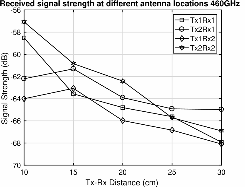
To explain these two discrepancies, it is helpful to plot the signal strength at different distances and for different combinations of antennas. In Figure 7 we plot this data for the 340GHz channel. First, note that the signal strength decreases with distance while we assume a constant SNR in the optimal plot in Figure 1. The other thing of note is that the received signal strength from transmit antenna 2 is greater than that from transmit antenna 1. This means the matrix cannot be which reduces capacity as well as changes the relationship between the optimal antenna spacing and transmit to receive distances. Finally, we plot the signal strength for 460 Ghz in Figure 8 to compare against Figure 7. The signal strength is much higher for the 460 Ghz band which explains its higher data rate overall. However, as in the case of the other frequencty bands, we see an asymmetrix receiver signal strength behavior.

V Related Work
For many years, the primary focus of terahertz research was on material sensing. For instance, due to the specific molecular absorption properties of various explosives, terahertz has been used to detect trace amounts of different compounds that are used in their manufacture. Terahertz has also been shown to be very effective in imaging the skin as a way to detect skin cancer. Airports utilize terahertz to image under clothing to search for weapons. Recently, terahertz has been employed to measure the thickness of coatings on medicines or automotive paint, etc [4, 19].
Research in utilizing terahertz for communications has lagged primarily due to the difficulty in manufacturing communication systems at these frequencies. The two commonly used devices for channel characterization that we utilize, for instance, are very expensive and are limited in power output. Recently, however, things have begun to change. For instance, Fujitsu recently demonstrated a compact 20 Gbps radio operating at 300 GHz [13]. Other work, such as [3] recently demonstrated a 4-element phased antenna array operating from 275 - 325 GHz.
Most of the research on terahertz communications has focused on point-to-point links utilizing simple modulation methods such as OOK (On Off Keyeing) and PSK (Phase Shift Keyeing). For example, 10 GBps data rates at 120 GHz were demonstrated in [6] for distances up to 6km. At the other end of the transmission range, [9] demonstrated transmissions using OOK at 220 GHz and achieved 50 Gbps over 50 cm. [16] achieved 8 Gbps at 250 GHz using ASK modulation. Recently, [7] demonstrated 106 Gbps at 400 GHz using a photonic wireless link. There have been other noteworthy demonstrations as well including [1, 21, 17, 2, 18, 12]. Finally, a significant milestone was achieved in [11] where they achieved 100 Gbps over 20m using a phased antenna array.
Our work is among the few to consider MIMO for terahertz frequencies. [10] was one of the earliest to study MIMO for 5G at 298-313 GHz. They utilized a measurment system similar to ours to show that a MIMO system is possible. However, they did not consider the impact of varying distances or other factors on the achievable channel capacity.
VI Conclusions
We present initial results of ongoing measurements for terahertz MIMO systems. We presented results for LoS MIMO capacity for three frequency bands in the terahertz spectrum that are being considered as possible communication windows. As expected, we note that increasing distance between transmitter and receiver results in lowering of capacity for all three frequency bands though 460 GHz appears to suffer the least degradation (14 bps/hz at 10 cm to 12 bps/hz at 25 cm). We observed that the receiver signal strength is asymmetric (i.e., Tx1 to Rx1 is weaker than Tx2 to Rx2, for example). This is something we are investigating currently as it results in unexpected capacity behavior. We are also extending our measurements to other frequency windows as well as to larger antenna arrays.
References
- [1] J. Antes, J. Reichart, D. Lopez-Diaz, A. Tessmann, F. Poprawa, F. Kurz, T. Schneider, H. Massler, and I. Kallfass. System concept and implementation of a mmW wireless link providing data rates up to 25 Gbit/s. In 2011 IEEE International Conference on Microwaves, Communications, Antennas and Electronics Systems (COMCAS), pages 1–4, Nov 2011.
- [2] G. Ducournau, P. Szriftgiser, A. Beck, D. Bacquet, F. Pavanello, E. Peytavit, M. Zaknoune, T. Akalin, and J.-F. Lampin. Ultrawide-bandwidth single-channel 0.4-THz wireless link combining broadband quasi-optic photomixer and coherent detection. 2014.
- [3] T. M. et al. Testbed for phased array communications from 275 to 325 ghz. In Proceedings IEEE Compound Semiconductor Integrated Circuit Symposium (CSCIS), 22-25 October 2017.
- [4] J. F. Federici, D. Gary, R. Barat, and D. Zimdars. THz standoff detection and imaging of explosives and weapons. In Defense and Security, pages 75–84. International Society for Optics and Photonics, 2005.
- [5] D. Gesbert, H. Bolcskei, D. Gore, and A. Paulraj. Outdoor mimo wireless channels: models and performance prediction. IEEE Transactions on Communications, 50(12):1926–1934, December 2002.
- [6] A. Hirata, T. Kosugi, H. Takahashi, J. Takeuchi, K. Murata, N. Kukutsu, Y. Kado, S. Okabe, T. Ikeda, F. Suginosita, et al. 5.8-km 10-Gbps data transmission over a 120-GHz-band wireless link. In 2010 IEEE International Conference on Wireless Information Technology and Systems (ICWITS),, pages 1–4. IEEE, 2010.
- [7] S. Jia, X. Pang, O. Ozolins, X. Yu, H. Hu, J. Yu, P. Guan, F. D. Ros, S. Popov, G. Jacobsen, M. Galili, T. Morioka, D. Zibar, and L. K. Oxenlowe. 0.4 thz photonic-wireless link with 106 gb/s single channel bitrate. Journal of Lightwave Technology, 36(2):610–616, January 2018.
- [8] J.-S. Jiang and M. A. Ingram. Distributed source model for short-range mimo. In Proceedings IEEE Vehicular Technology Conference, October 2003.
- [9] I. Kallfass, J. Antes, T. Schneider, F. Kurz, D. Lopez-Diaz, S. Diebold, H. Massler, A. Leuther, and A. Tessmann. All active MMIC-based wireless communication at 220 GHz. IEEE Transactions on Terahertz Science and Technology, 1(2):477–487, November 2011.
- [10] N. Khalid and O. B. Akan. Experimental throughput analysis of low-thz mimo communication channel in 5g wireless networks. IEEE Wireless Communication Letters, 5(6):616–619, December 2016.
- [11] S. Koenig, D. Lopez-Diaz, J. Antes, F. Boes, R. Henneberger, A. Leuther, A. Tessmann, R. Schmogrow, D. Hillerkuss, R. Palmer, T. Zwick, C. Koos, W. Freude, O. Ambacher, J. Leuthold, and I. Kallfass. Wireless sub-THz communication system with high data rate. Nature Photonics, 7:977–981, October 2013.
- [12] B. Lu, W. Huang, C. Lin, and C. Wang. A 16QAM modulation based 3Gbps wireless communication demonstration system at 0.34 THz band. In Infrared, Millimeter, and Terahertz Waves (IRMMW-THz), 2013 38th International Conference on, pages 1–2. IEEE, 2013.
- [13] Y. Nakasha, S. Shiba, Y. Kawano, and T. Takahashi. Compact terahertz receiver for short-range wireless communications of tens of gbps. Fujitsu Science and Technology Journal, 53(2):9–14, Feburary 2017.
- [14] I. Sarris and A. R. Nix. Maximum mimo capacity in line-of-sight. In International Conference on Information Communications and Signal Processing, Bankok, Thailand, 6-9 December 2005.
- [15] C. Sheldon, E. Torkildson, M. Seo, C. P. Yue, M. Rodwell, and U. Madhow. Spatial multiplexing over a line-of-sight millimeter-wave mimo link: two-channel hardware demonstration at 1.2gbps over 41m range. In European Conference on Wireless Technology, pages 198–201, 27-28 October 2008.
- [16] H. Song, K. Ajito, A. Hirata, A. Wakatsuki, T. Furuta, N. Kukutsu, and T. Nagatsuma. Multi-gigabit wireless data transmission at over 200-GHz. In 34th International Conference on Infrared, Millimeter, and Terahertz Waves, 2009. IRMMW-THz 2009, pages 1–2, 2009.
- [17] H. Song, K. Ajito, Y. Muramoto, and A. Wakatasuki. 24 Gbit/s data transmission in 300 GHz band for future terahertz communications. Electronics Letters, 48(15):953–954, July 2012.
- [18] C. Wang, C. Lin, Q. Chen, B. Lu, X. Deng, and J. Zhang. A 10-Gbit/s wireless communication link using 16-QAM modulation in 140-GHz band. IEEE Transactions on Microwave Theory and Techniques, 61(7):2737–2746, July 2013.
- [19] D. Woolard, P. Zhao, C. Rutherglen, Z. Yu, P. Burke, S. Brueck, and A. Stintz. Nanoscale imaging technology for THz-frequency transmission microscopy. International Journal of High Speed Electronics and Systems, 18(01):205–222, 2008.
- [20] K. Yu, M. Bengtsson, B. Ottersten, and M. Beach. Narrowband mimo channel modeling for los indoor scenarios. In Proceedings 27th Triennial General Assembly of the International Union of Radio Science, Maastricht, The Netherlands, August 2002.
- [21] B. Zhang, Y.-Z. Xiong, L. Wang, and S. Hu. A switch-based ASK modulator for 10 Gbps 135 GHz communication by 0.13 MOSFET. IEEE Microwave and Wireless Components Letters, 22(8):415–417, 2012.