Maximizing Network Connectivity for UAV Communications via Reconfigurable Intelligent Surfaces
Abstract
It is anticipated that integrating unmanned aerial vehicles (UAVs) with reconfigurable intelligent surfaces (RISs), resulting in RIS-assisted UAV networks, will offer improved network connectivity against node failures for the beyond 5G networks. In this context, we utilize a RIS to provide path diversity and alternative connectivity options for information flow from user equipment (UE) to UAVs by adding more links to the network, thereby maximizing its connectivity. This paper employs the algebraic connectivity metric, which is adjusted by the reflected links of the RIS, to formulate the problem of maximizing the network connectivity in two cases. First, we consider formulating the problem for one UE, which is solved optimally using a linear search. Then, we consider the problem of a more general case of multiple UEs, which has high computational complexity. To tackle this problem, we formulate the problem of maximizing the network connectivity as a semi-definite programming (SDP) optimization problem that can be solved efficiently in polynomial time. In both cases, our proposed solutions find the best combination between UE(s) and UAVs through the RIS. As a result, it tunes the phase shifts of the RIS to direct the signals of the UEs to the appropriate UAVs, thus maximizing the network connectivity. Simulation results are conducted to assess the performance of the proposed solutions compared to the existing solutions.
Index Terms:
Network connectivity, algebraic connectivity, RIS-assisted UAV communications, graph theory.I Introduction
UAVs are expected to have a remarkable impact on the economy by 2026 with a global market value of US$59.2 billion, making the incorporation of UAVs critical in beyond 5G networks [1]. One of the unique features of UAV-assisted communication is improved network connectivity by establishing line-of-sight (LoS) connections with UEs [2]. Meanwhile, RIS is a promising technique that is integrated with UAVs to further improve network connectivity [3], particularly in networks that experience deep fade. In this context, RISs can be leveraged to provide path diversity and alternative connectivity solutions for information flow from UEs to UAVs in RIS-assisted UAV networks.
The prime concern of UAV communications is that UAV nodes are prone to failure due to several reasons, such as limited energy, hardware failure, or targeted failure in the case of battlefield surveillance systems. Such UAV failures cause network disintegration, and consequently, information flow from UEs to a fusion center through UAVs can be severely impacted. Hence, it is crucial to always keep the network connected, which was addressed in the literature by adding more backhual links to the network, e.g., [4]. In spite of recent advances in wireless sensor networks, most of the existing studies consider routing solutions with the focus more on extending the battery lifetime of sensor nodes. These works define network connectivity as network lifetime, in which the first node or all the nodes have failed [5, 6]. However, none of the aforementioned works has ever explicitly considered the exploitation of RISs to add more reflected links for improving network connectivity. Different from works [5, 6] that focused on routing solutions, this paper focuses on designing a more connected RIS-assisted UAV network that enables information flow from the UEs to the UAVs even if some of the UAVs have failed.
The algebraic connectivity [7], also called the Fiedler metric or the second smallest eigenvalue of the Laplacian matrix representing a graph, is a metric that measures how well a graph is connected. In the literature, such metric is usually associated with network connectivity [8, 9, 10]. In [8], the authors maximized the algebraic connectivity by positioning the UAV to maximize the connectivity of small-cells backhaul network. A more general study in [9] proposed different network maintenance algorithms to maximize the connectivity of wireless sensor networks. Since the algebraic connectivity is a good measure of how connected the graph is, the more edges that exist between the UEs and the UAVs, the more resilient network can be designed without being disconnected due to node failures [9, 10]. To this end, this paper aims to utilize the RIS to add link redundancy to the network and tune the RIS phase shift configurations to direct UEs’ signals to appropriate UAVs, so that the connectivity of RIS-assisted UAV networks is maximized. To the best of our knowledge, the problem of maximizing the network connectivity in RIS-assisted UAV networks has not been studied before in the literature.
In this paper, we address this problem by employing the concept of algebraic connectivity [7] of a graph in network connectivity, then we consider two problem cases. First, we formulate the problem for one UE and one RIS and solve it optimally via a linear search. Then, we formulate the problem for a more general case of multiple UEs and one RIS. It is shown that solving this general problem optimally is computationally prohibitive since it requires computing the algebraic connectivity of the resulting network for each possible edge that connects the UEs to the UAVs through the RIS. To tackle this problem, we adjust the algebraic connectivity metric of the original graph network by the candidate edges between the UEs and the UAVs via the RIS. Then, we reformulate the problem of maximizing the network connectivity as a semi-definite programming (SDP) optimization problem that can be solved efficiently in polynomial time. In both cases, our proposed solutions find the best combination between the UE(s) and the UAVs through the RIS by tuning its phase shifts to direct the UEs’ signals to the appropriate UAVs, thus maximizing the network connectivity. Simulation results are conducted to assess the performance of the proposed solutions compared to the existing solutions.
II System Model and Network Connectivity
II-A System Model
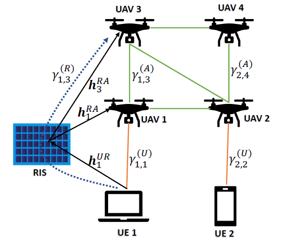
We consider a RIS-assisted UAV network with a set of UAVs, one RIS, and multiple UEs that represent ground users, sensors, etc. An example of the considered network is shown in Fig. 1. The sets of UAVs and UEs are denoted as and , respectively, where is the cardinality of the set . All UEs and UAVs are quipped with single antennas. The UAVs fly and hover over assigned locations at a fixed flying altitude and connect UEs with the fusion center. The locations of the UAVs, UEs, and the RIS are assumed to be fixed. We assume that all channels follow a quasi-static flat-fading model and thus remain constant over one time slot. The RIS is installed with a certain altitude . Let be the 2D location of the RIS, be the 3D location of the -th UAV, and be the 2D location of the -th UE, respectively. The distances between the -th UE and the RIS and between the RIS and the -th UAV are denoted by and , respectively.
Due to their altitude, UAVs can have good connectivity to UEs. However, UEs may occasionally experience deep fade. To overcome this problem and further improve network connectivity, we propose to utilize a RIS to impose link redundancy to the RIS-assisted UAV network. As such, the network becomes more resilient against node failures by providing path diversity and alternative connectivity options between UEs and UAVs. The RIS is equipped with a controller and passive reflecting units (PRUs) to form a uniform passive array (UPA). Each column of the UPA has PRUs with an equal spacing of meters (m) and each row of the UPA consists of PRUs with an equal spacing of m. These PRUs can add indirect links between UEs and UAVs with adjustable phase shifts. The phase-shift matrix of the RIS is modeled as the diagonal matrix , where , for and .
The successful communications between the UEs and the RIS are measured using the distance threshold , i.e., the -th UE is connected to the RIS with distance if . The communications between the UEs and UAVs/RIS are assumed to occur over different time slots (i.e., time multiplexing access) to avoid interference among the scheduled UEs. Therefore, we assume that only one UE is transmitting in each time slot to reduce interference. Considering the interference among the different scheduled UEs to the RIS and the UAVs is left for future work.
Since this paper focuses on the network connectivity from data link-layer viewpoint, we abstract the physical layer factors and consider a model that relies only on the distance between the nodes. Therefore, we model only the large scale fading and ignore the small scale fading. To quantify the UEs transmission to the UAVs and the RIS, we use the signal-to-noise ratio (SNR). For the -th UE, SNR is defined as follows [8]
| (1) |
where is the distance between the -th UE and the -th UAV, is the transmit power of the -th UE, which is maintained fixed for all the UEs, is the additive white Gaussian noise (AWGN) variance, and is the path loss exponent that depends on the transmission environment.
UAVs hover at high altitudes, thus we reasonably assume that they maintain LoS channel between each other. The path loss between the -th and the -th UAVs can be expressed as
| (2) |
where is the distance between the -th UAV and the -th UAV, is the carrier frequency, and is light speed. The SNR in dB between the -th UAV and the -th UAV is , where is the transmit power of the -th UAV, which is maintained fixed for all the UAVs. Note that the SNR of the -th UE determines whether it has a successful connection to the corresponding UAV . In other words, the -th UAV is assumed to be within the transmission range of the -th UE if , where is the minimum SNR threshold for the communication links between the UEs and the UAVs. Similarly, we assume that UAV and UAV have a successful connection provided that , where is the minimum SNR threshold for the communication links between the UAVs.
Since the RIS is deployed in the higher altitude, the signal propagation of UE-to-RIS link is adopted to be a simple yet reasonably accurate LoS channel model [11]. The LoS channel vector between the -th UE and the RIS is given by [11]
| (3) |
where is the distance between the -th UE and the RIS, denotes the path loss at the reference distance m, and represents the array response component which can be denoted by
where , and are related to the sine and cosine terms of the vertical and horizontal angles-of-arrival (AoAs) at the RIS [11], and given by , , , is the wavelength, and denotes transpose. On the other hand, the RIS and UAVs are deployed in the higher altitudes, thus the reflected signal propagation of the RIS-to-UAV link typically occurs in clear airspace where the obstruction or reflection effects diminish. The LoS channel vector between the RIS and the -th UAV is given by
| (4) |
where is the distance between the RIS and the -th UAV, and represents the array response component which can be denoted by
where , and are related to the sine and cosine terms of the vertical and horizontal angles-of-departure (AoDs) from the RIS to the -th UAV [11], and respectively given by , , and .
Given the aforementioned channel models, the concatenated channel for the UE-RIS-UAV link between the -th UE and the -th UAV through the RIS is given by [11]. Accordingly, the SNR of the reflected link between the -th UE and the -th UAV through the RIS can be written as [12]. For successful connection between UE and UAV via RIS , , where is the minimum SNR threshold for the communication links between the UEs and the UAVs via the RISs.
We model the considered RIS-assisted UAV network as an undirected graph , where is the set of nodes (i.e., UAVs and UEs) in the network, is the set of all edges. and are the numbers of vertices and edges in the graph, respectively. The graph implies that all the links in the network are bidirectional, i.e., a node is able to reach node , and vice versa. The edge between any two nodes is created based on a typical SNR threshold.
II-B Network Connectivity
For an edge , , that connects two nodes , let be a vector, where the -th and -th elements in are given by and , respectively, and zero otherwise. The incidence matrix of a graph is the matrix with the -th column given by . Hence, in undirected graph , the Laplacian matrix is an by matrix, which is defined as follows [9]:
| (5) |
where the entries of are given as follows:
| (6) |
where are the indices of the nodes, and is the degree of node , which represents the number of all its neighboring nodes.
In network connectivity, algebraic connectivity, also called the Fiedler metric or the second smallest eigenvalue [7], measures how well a graph that has the associated Laplacian matrix is connected. From its name, this metric is usually denoted as . The motivation of to be used as a network connectivity metric comes from the following two main reasons [7]. First, if and only if is connected, i.e., is only one connected graph. It is worth mentioning that when , the graph is disconnected in which at least one of its vertices is unreachable from any other vertices in the graph. Second, is monotone increasing in the edge set, i.e., if and and , then . This implies that qualitatively represents the connectivity of a graph in the sense that the larger is, the more connected the graph will be. To this end, since is a good measure of how connected the graph is, the more edges that exist between the UEs and the UAVs, the longer the network can live without being disconnected due to node failures. Thus, the network becomes more resilient. Based on that, we consider as a quantitative measure of the network resiliency in this paper, similar to [9, 13].
III Problem Formulation
Given a RIS-assisted UAV network represented by a graph , what are the optimum combinations between the UEs and the UAVs through the RIS in order to maximize of the resulting network? Essentially, adding the RIS to the network may result in connecting multiple UEs to multiple UAVs, which were not connected together. It may also result in adding new alternative options to the UEs if their scheduled UAVs have failed. In this context, we leverage the RIS to add more links to the network, and by adjusting its phase shifts, RIS can smartly beamform the signals of the UEs to suitable UAVs to maximize the network connectivity.
With RIS deployment, a new graph is constructed with the same number of nodes and a larger set of edges denoted by with , where is the new edge connecting the -th UE to the -th UAV through the RIS and . Note that the effect of deploying the RIS appears only in the edge set , and not in the node set [8, 9, 10]. By adding those new links to the network, the gain can be realized by computing , where is the resulting Laplacian matrix of a graph .
We consider that in each time slot only one UE can transmit to the RIS, which directs the UE’s signal to only one UAV. In what follows, we consider two different cases of network configurations to formulate the optimization problem of maximizing in each time slot.
Case 1: One UE and One RIS
Let be a set of reachable UAVs that have indirect communication links from the UE through the RIS, i.e., , where is the set of UAVs that have direct links to the UE. Our aim is to provide an alternative link to connect the UE to a single UAV in the set . As such, the UE does not miss the communication if its scheduled UAV has failed. Now, let be a binary variable that is equal to if the RIS is connected to the -th UAV (), and zero otherwise. The considered optimization problem in this case is formulated as follows:
| (7a) | |||
| (7b) | |||
| (7c) | |||
| (7d) | |||
where constraint (7b) assures that the RIS directs the signal of the UE to only one UAV. Constraint (7c) is for the RIS phase shift optimization.
Case 2: Multiple UEs and One RIS
Unlike case 1 that considers one UE, case 2 adds an optimization variable that selects the -th UE that transmits in each time slot. Let be a set of reachable UAVs that have indirect communication links from the -th UE through the RIS, i.e., , where is the set of UAVs that have direct links to the -th UE. Let be a binary variable that is equal to if the -th UE is connected to the RIS, and zero otherwise. Now, let be a binary variable that is equal to if the RIS is connected to the -th UAV when the -th UE is selected to transmit, and zero otherwise. The considered optimization problem in this case is formulated as follows:
| (8a) | |||
| (8b) | |||
| (8c) | |||
| (8d) | |||
| (8e) | |||
where constraint (8b) and (8c) assure that only one UE can transmit to the RIS and the signal of that UE is reflected from the RIS to only one UAV. Constraint (8d) is for the RIS phase shift optimization.
IV Proposed Solutions
It is computably affordable to optimally solve (7) since it considers only one UE, however solving (8) optimally for the case of multiple UEs is computationally prohibitive. Therefore, this section proposes to solve (7) optimally using a linear search over all the possible UAV nodes. Then, the section formulates (8) as an SDP optimization problem that can be solved efficiently in polynomial time. The process of those proposed solutions are explained in subsections IV-A and IV-B, respectively.
IV-A Solution of Case 1
To optimally solve (7), we consider a linear search scheme that computes for each possible UAV node , and then calculate the corresponding phase shift of the RIS to that UAV node. In particular, the corresponding phase shift at PRU of the RIS to the -th UAV is calculated as follows [11]
| (9) |
We argue that the computational complexity of the proposed solution of this case is affordable since it needs to compute only Laplacian matrices. The steps of the proposed method are summarized in Algorithm 1.
IV-B Solution of Case 2
The exhaustive search scheme to solve (8) for multiple UEs can be done by computing for a total of Laplacian matrices, which requires huge amount of computation for large . For graph , the time complexity of the exhaustive search is high for large network settings. It runs in to compute [14]. To overcome such computational intractability, we instead propose an efficient method to solve (8), which finds the feasible UE-RIS-UAV association to maximize using SDP solvers [15].
We add a link connecting the -th UE to the -th UAV through the RIS if both and in (8) are . Let be a vector representing the UE-RIS-UAV candidate associations, in which case and , . Therefor, the problem in (8) can be seen as having a set of UE-RIS-UAV candidate associations, and we want to select the optimum UE-RIS-UAV association among these associations. This optimization problem can be formulated as
| (10) | |||
where is the all-ones vector and
| (11) |
where is the incidence vector resulting from adding link to the original graph and is the Laplacian matrix of the original graph . Clearly, the dimension of and is .
The optimization vector in (12) is the vector . The -th element of , denoted by , is either or , which corresponds to whether this UE-RIS-UAV association should be chosen or not, respectively. The combinatorial optimization problem in (12) is NP-hard problem with high complexity. Therefore, we relax the constraint on the entries of and allow them to take any value in the interval . Specifically, we relax the Boolean constraint to be a linear constraint , then we can represent the problem (12) as
| (12) | |||
We emphasize that the optimal solution of the relaxed problem in (14) is an upper bound for the optimal solution of the original problem (12) since it has a larger feasible set. In [10], it was shown that in (14) is the point-wise infimum of a family of linear functions of , which is a concave function in . In addition, the relaxed constraints are linear in . Therefore, the optimization problem in (14) is a convex optimization problem [10], and it is equivalent to the following SDP optimization problem [16]
| (13) | |||
where is the identity matrix and denotes that is a positive semi-definite matrix.
By solving the SDP optimization problem in (15) efficiently using any SDP standard solver such as the CVX software package [15], the optimization variable is obtained. Since the entries of the output vector are continuous, we consider to round the maximum entry to while others are rounded to zero. For the given association vector , we optimize the phase shift of the RIS as in (11) to direct the signal of the selected UE to the associated UAV.
V Numerical Results
For the numerical evaluations, we use the same RIS configurations and UAV communications that were used in [8] and [11], respectively. We consider a RIS-assisted UAV system in an area of , where the RIS has a fixed location and the UEs and the UAVs are distributed randomly. The considered simulation parameters are as follows: the RIS is located at () with an altitude of m, , cm, cm, , dBm, the altitude of the UAVs is m, Hz, m/s, , watt, watt, dB, and dB. Unless specified otherwise, , , and dB.
For the sake of numerical comparison, the proposed schemes are compared with the following schemes: 1) original benchmark scheme without RIS deployment, 2) random scheme that selects a random link to connect the UE to one of the UAVs through the RIS. For completeness of our work, we also compare the proposed SDP scheme of case with the optimal scheme that is considered as a performance upper bound since it searches over all the possible links between the UEs and the UAVs. In the simulations, the network connectivity is calculated over iterations, and the average value is presented. In each iteration, we change the locations of the UEs and the UAVs.
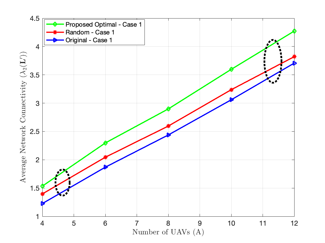
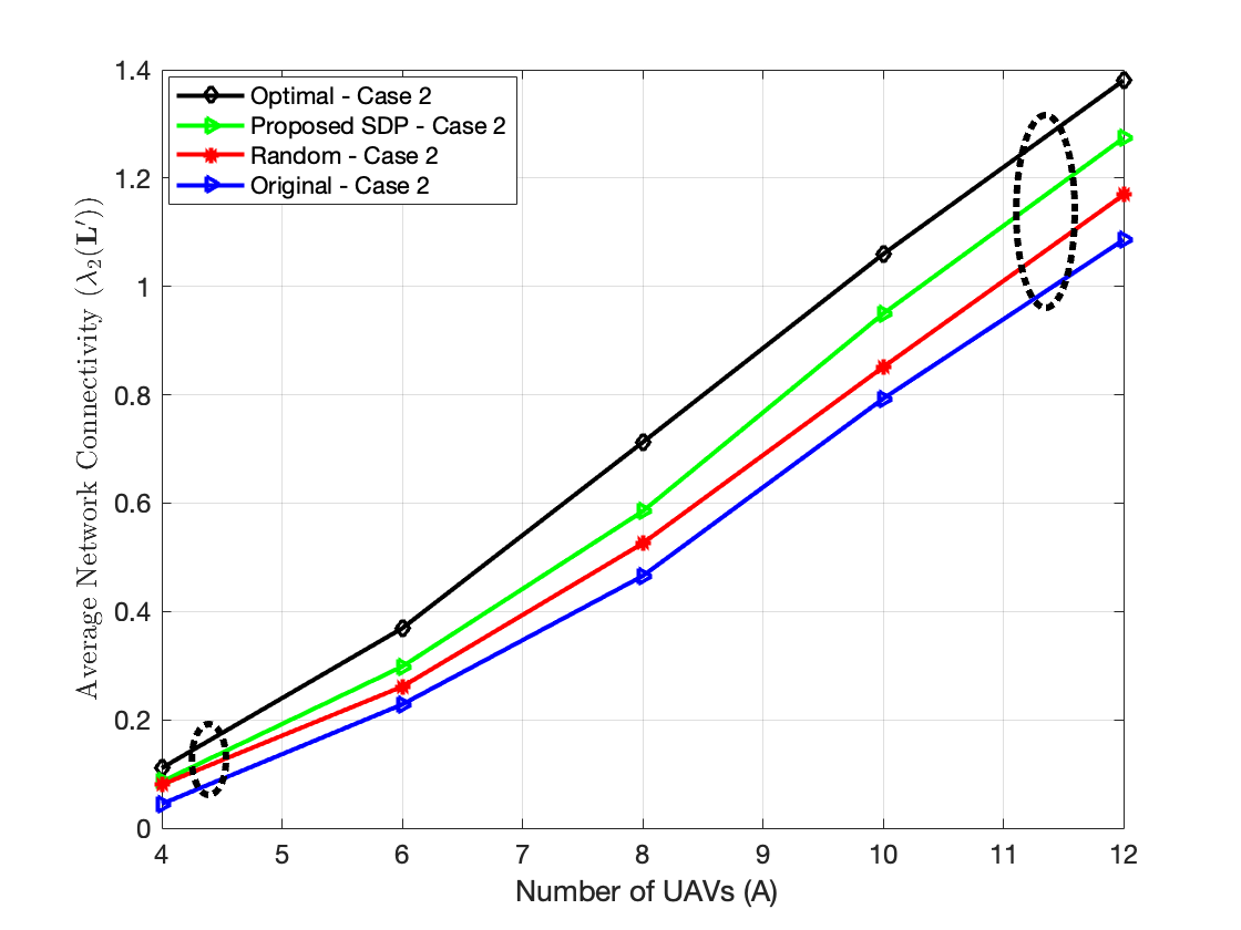
In Figs. 2 and 3, we show the average network connectivity versus the number of UAVs for both cases. For a small number of UAVs in Figs. 2 and 3, the proposed optimal and SDP schemes offer a slight performance gain in terms of network connectivity compared to the original and the random schemes. This is because our proposed schemes have a few options of links, where the RIS can direct the signal of the UE to a few number of UAVs. However, when the number of UAVs increases, the proposed schemes smartly selects an effective UE-RIS-UAV link that significantly maximizes the network connectivity. It is noted that of all schemes increases with the number of UAVs since adding more connected nodes to the network increases the number of edges, which increases the network connectivity. It is also noted that the values of in Fig. 3 are smaller than the values of in Fig. 2 for all the UAVs configurations. This is reasonably because the number of unconnected nodes that represent the UEs in Fig. 3 of case , i.e., , is larger than those of Fig. 2 of case , which is one UE. This makes the network of case less connected (i.e., more UE nodes and no links between them), thus low network connectivity in Fig. 3. When in Fig. 3, the average network connectivity of all the schemes increases significantly with , which follows the same behaviour of Fig. 2 that is .
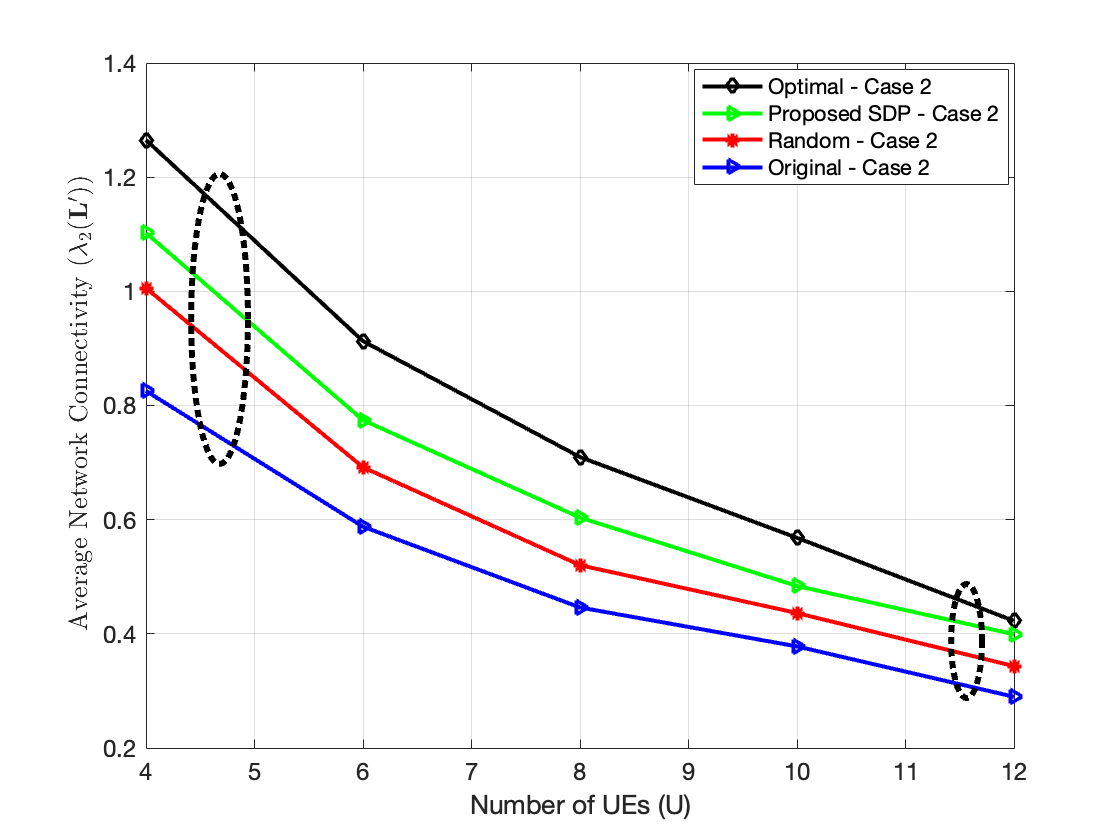
In Fig. 4, we plot the network connectivity versus the number of UEs for case . From Fig. 4, we can see that the proposed SDP outperforms the original and the random schemes in terms of network connectivity. Notably, the network connectivity of all the schemes decreases as the number of UEs increases, since adding more unconnected UEs may result in a sparse graph with low network connectivity.
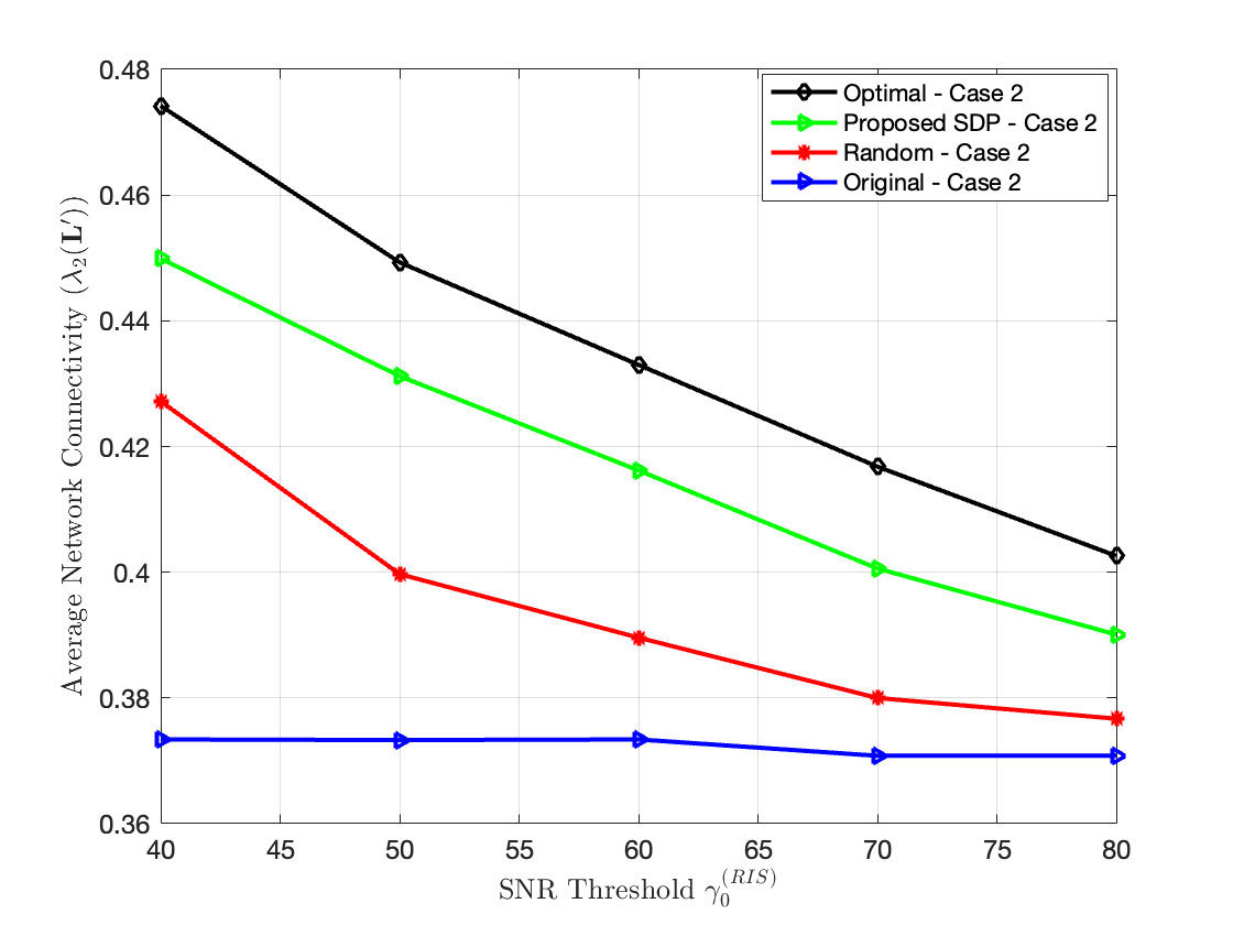
In Fig. 5, we show the impact of the SNR threshold on the network connectivity for case . For small SNR threshold, all the links between the UEs and the UAVs through the RIS can satisfy this SNR threshold, thus many alternative links between the potential UE and the UAVs to select to maximize the network connectivity. On the other hand, for high RIS SNR threshold, a few UE-RIS-UAV links can satisfy such high SNR threshold, thus the network connectivity of all the schemes is degraded, and it becomes close to the original scheme, which does not get affected by changing .
It is worth remarking that while the random scheme adds a random link to the network, the original scheme does not add a link. The proposed solutions balance between the aforementioned aspects by judiciously selecting an effective link, between a UE and a UAV, that maximizes the network connectivity. This utilizes the benefits of the cooperation between an appropriate scheduling algorithm design and RIS phase shift configurations. Compared to the optimal scheme, our proposed SDP has a certain degradation in network connectivity that comes as the achieved polynomial computational complexity as compared to the high complexity of the optimal scheme that is in the order of [14].
VI Conclusion
In this paper, we proposed a novel joint UE-UAV scheduling and RIS phase shift optimization for achieving connected and resilient RIS-assisted UAV networks. We leveraged the RIS to add more links to the network by opportunistically reflecting the signal of the UE to the appropriate UAV such that the network connectivity is maximized. The problem of maximizing the network connectivity was formulated in two cases of a single UE and multiple UEs, and optimal and efficient SDP solutions were proposed for the two problem cases, respectively. Simulation results showed that both the proposed schemes result in improved network connectivity as compared to the existing solutions. Such promising performance gain can be significantly improved for the case of multiple RISs, which will be pursued in our future work.
References
- [1] L. Godage, “Global unmanned aerial vehicle market (UAV) industry analysis and forecast (2018-2026),” Mont. Ledger Boston, MA, USA, 2019.
- [2] Mohammed S. Al-Abiad and M. J. Hossain, “Coordinated scheduling and decentralized federated learning using conflict clustering graphs in fog-assisted IoD networks,” IEEE Trans. on Vehicular Tech. vol. 72, no. 3, pp. 3455-3472, Mar. 2023.
- [3] M. Ammous and S. Valaee, “Cooperative positioning with the aid of reconfigurable intelligent surfaces and zero access points,” 2022 IEEE 96th Vehicular Tech. Conf. (VTC2022-Fall), London, United Kingdom, 2022, pp. 1-5.
- [4] H. Dahrouj et al., “Cost-effective hybrid RF/FSO backhaul solution for next generation wireless systems,” in IEEE Wireless Commun., vol. 22, no. 5, pp. 98-104, Oct. 2015.
- [5] Jae-Hwan Chang and L. Tassiulas, “Maximum lifetime routing in wireless sensor networks,” in IEEE/ACM Trans. on Networking, vol. 12, no. 4, pp. 609-619, Aug. 2004.
- [6] W. R. Heinzelman et al., “Energy-efficient communication protocol for wireless microsensor networks,” Proc. of the 33rd Annual Hawaii Intern. Conf. on System Sciences, Maui, HI, USA, 2000, pp. 10 pp. vol. 2.
- [7] M. Fiedler, “Algebraic connectivity of graphs,” Czechoslovak Mathe- matical J., vol. 23, pp. 298-305, 1973.
- [8] M. A. Abdel-Malek, A. S. Ibrahim, and M. Mokhtar, “Optimum UAV positioning for better coverage-connectivity tradeoff,” 2017 IEEE 28th Annual Intern. Symposium on Personal, Indoor, and Mobile Radio Commun. (PIMRC), Montreal, QC, Canada, 2017, pp. 1-5.
- [9] C. Pandana and K. J. R. Liu, “Robust connectivity-aware energy-efficient routing for wireless sensor networks,” in IEEE Trans. on Wireless Commun., vol. 7, no. 10, pp. 3904-3916, Oct. 2008.
- [10] A. S. Ibrahim, K. G. Seddik and K. J. R. Liu, “Connectivity-aware network maintenance and repair via relays deployment,” in IEEE Trans. on Wireless Commun., vol. 8, no. 1, pp. 356-366, Jan. 2009.
- [11] Z. Wei et al., “Sum-rate maximization for IRS-assisted UAV OFDMA communication systems,” in IEEE Trans. on Wireless Commun., vol. 20, no. 4, pp. 2530-2550, Apr. 2021.
- [12] A. Albanese, P. Mursia, V. Sciancalepore and X. Costa-Pérez, “PAPIR: Practical RIS-aided localization via statistical user information,” 2021 IEEE 22nd Inter. Workshop on Signal Processing Advances in Wireless Commun. (SPAWC), Lucca, Italy, 2021, pp. 531-535.
- [13] N. Li and J. C. Hou, “Improving connectivity of wireless ad hoc networks,” in Proc. Second Annual Inter. Conf. on Mobile and Ubiquitous Systems: Netw. and Services (MobiQuitous’05), pp. 314-324, July 2005.
- [14] G. H. Golub and C. F. Van Loan, “Matrix computations,” Math. Gazette, vol. 47, no. 5, pp. 392–396, 2013.
- [15] SDPA-M package, [Online]. Available: http://grid.r.dendai.ac.jp/sdpa/
- [16] S. Boyd, “Convex optimization of graph laplacian eigenvalues,” in Proc. Inter. Congress of Mathematicians, vol. 3, pp. 1311-1319, 2006.