Material survey for millimeter-wave absorber using 3-D printed mold
Abstract
Radio absorptive materials (RAMs) are key elements for receivers in the millimeter-wave range. For astronomical applications, cryogenic receivers are widely used to achieve a high-sensitivity. These cryogenic receivers, in particular the receivers for the cosmic microwave background, require that the RAM has low surface reflectance () in a wide frequency range (20–300 GHz) to minimize the undesired stray light to detectors. We develop a RAM that satisfies this requirement based on a production technology using a 3D-printed mold (named as RAM-3pm). This method allows us to shape periodic surface structures to achieve a low reflectance. A wide range of choices for the absorptive materials is an advantage. We survey the best material for the RAM-3pm. We measure the index of refraction () and the extinction coefficient () at liquid nitrogen temperature as well as at room temperature of 17 materials. We also measure the reflectance at the room temperature for the selected materials. The mixture of an epoxy adhesive (STYCAST-2850FT) and a carbon fiber (K223HE) achieves the best performance. We estimate the optical performance at the liquid nitrogen temperature by a simulation based on the measured and . The RAM-3pm made with this material satisfies the requirement except at the lower edge of the frequency range (20 GHz). We also estimate the reflectance of a larger pyramidal structure on the surface. We find a design to satisfy our requirement.
I Introduction
Radio absorptive materials (RAMs) are indispensable elements for receivers in the millimeter-wave range. Their role is the mitigation of unexpected external noise (hereafter stray light), which may enter the receiver from outside of its line of sight. Radio sensors in the receiver are generally maintained at cryogenic condition in the cases of cosmological and astronomical applications, e.g., the cosmic microwave background (CMB) observation. In these applications, a major source of the stray light is thermal radiations from the ambient environment. Because sensors based on a superconducting device have a high sensitivity Ade et al. (2019), it is very important to avoid any stray light entering the sensors.
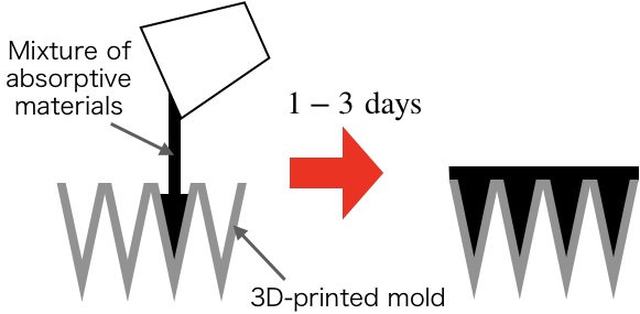
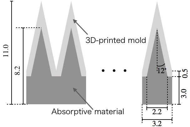
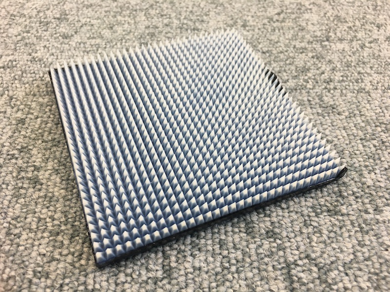
Shaping the periodic surface structures, e.g., a pyramid shape, is an important point in achieving a low surface reflectance. We previously established a production method for RAMs using a 3D-printed mold Adachi et al. (2020) (named as RAM-3pm). As illustrated in Fig. 1, we can shape the structure by filling an epoxy adhesive (STYCAST-2850FT) into a 3D-printed mold. Its geometry and a photograph are shown in Fig. 2. The mold is thin (thickness of 0.5 mm) and almost transparent Adachi et al. (2020). Therefore, we do not need to remove the mold. We also confirmed that the mold is usable for cryogenic application. A wide range of choices for the filling material is an important advantage of the RAM-3pm compared with the other RAMs Xu et al. (2021); Petroff et al. (2019).
In this paper, we survey the best material for the RAM-3pm. We focus on the CMB application, which requires a low surface reflectance () in a wide frequency range (20–300 GHz) in a cryogenic condition Ade et al. (2019). In section II, we prepare 17 materials. In section III, we make flat-shaped samples, which are a mixture of each material and STYCAST-2850FT, and we measure their optical properties: index of refraction and extinction coefficient. To evaluate the performance at low temperature, we perform these measurements at liquid nitrogen temperature (77 K) as well as at room temperature ( K). In section IV, we select candidate materials based on these optical parameters, and we make a RAM-3pm for each of them. Their surface reflectance is measured at room temperature. We check the consistency between the measurement and simulation using the measured optical parameters. In section V, we estimate their performance at 77 K including their scattering effects. We provide our conclusions in section VI.
II Materials
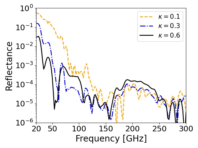
The surface reflectance of the RAM relies on the surface structure and optical properties of the material, i.e., the index of refraction () and extinction coefficient (). Figure 3 shows the simulation results for three cases: = (2.3, 0.1), (2.3, 0.3), and (2.3, 0.6) for the RAM whose geometry is defined in Fig. 2. We used ANSYS-HFSSANSYS, Inc. for the simulation, and we assumed unpolarized light whose incident angle was 45∘. We set a perfect conductor at the backside of the RAM in the simulation. We found that a lower reflectance is obtained with a larger in the low frequency range, where the reflectance is relatively high. We can intuitively understand this by the formula that describes light attenuation: Lambert’s law Jackson (1999),
| (1) |
where is the output power through the material, is the power of input light, is the frequency, is the thickness of the optical path, and is the speed of light. Finding a material that has a large is our strategy to achieve our requirement.
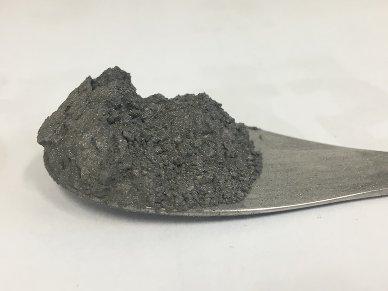
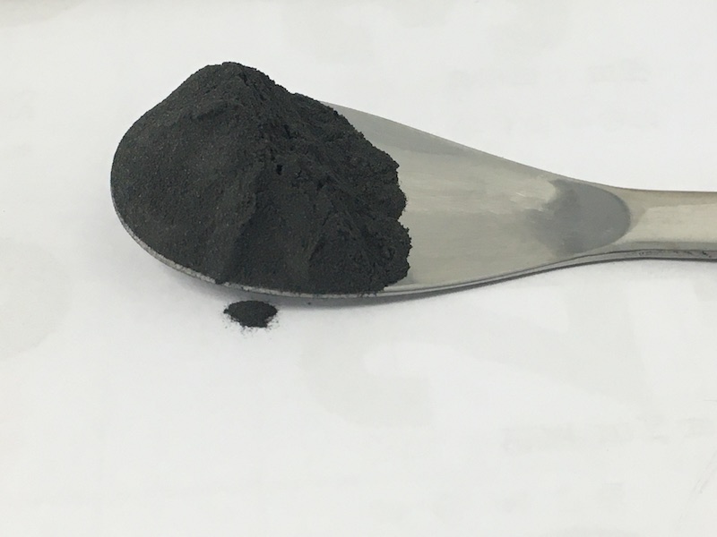
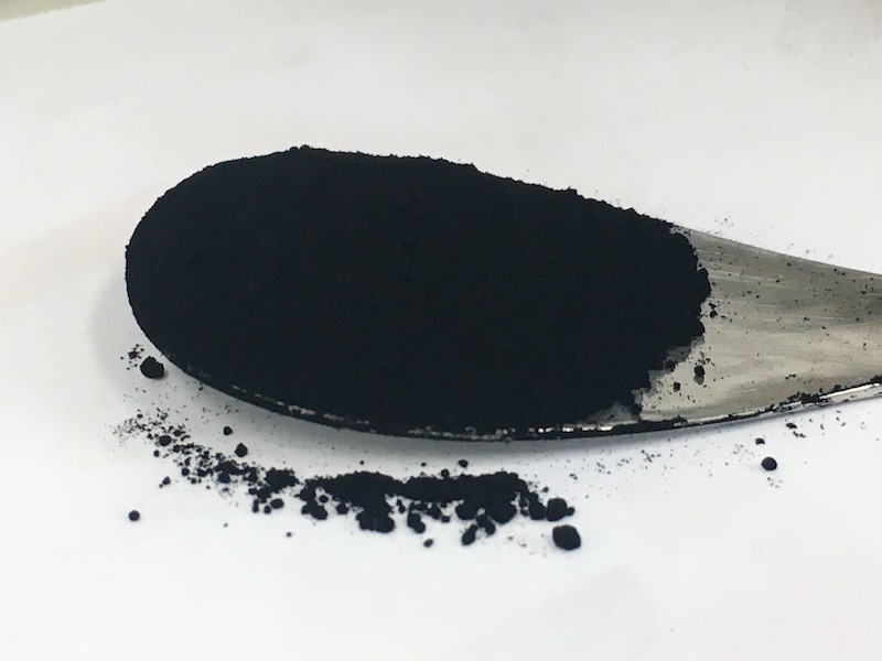
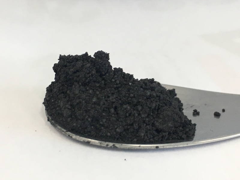
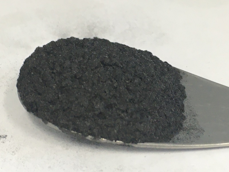
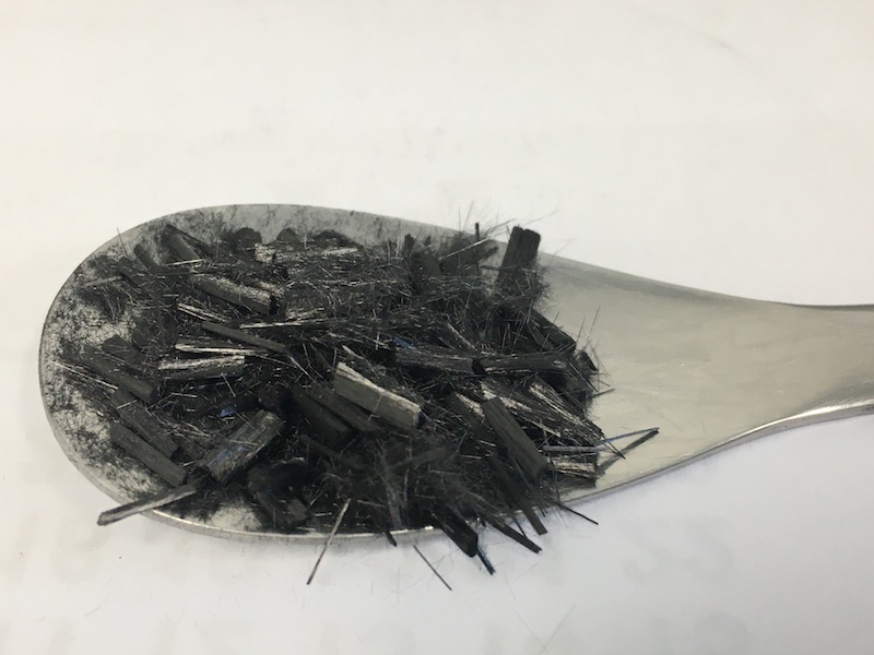
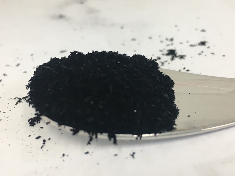
We used mixtures of a base material and absorptive materials. We selected STYCAST-2850FTHenkel Japan Ltd. as the base material because it has been widely used for cryogenic applications. The RAM-3pm made with this material has a sufficient mechanical strength and a good thermal conductivity in the cryogenic condition according to our previous study Adachi et al. (2020). For the materials mixed into the STYCAST-2850FT, we prepared stainless steel powders and carbon materials because they are expected to have a large owing to their electrical conductivity. These are listed in Table 1. This table includes their product names, their particle sizes, and the weight fractions of each mixture sample. We surveyed 17 materials in total. Photos of seven of them are shown in Fig. 4. The weight fraction was determined to maintain a low viscosity for easy fabrication of the RAM-3pm. It was approximately in the case of the carbon fiber K223HE.
| Types of materials | Product name | Particle size | Photo index at Fig. 4 | Weight fraction | |
| Stainless steelToyo Aluminium K.K. | Spherical shape | RD19-3532 | (a) | 20% | |
| Flat shape | RFA6500 | – | 7% | ||
| Graphite Ito Graphite Co., Ltd. | Spherical graphite | SG-BL40 | (b) | 14% | |
| Flake graphite | Z-50 | – | 4% | ||
| Pyrolytic graphite | PC99-300M | – | 3.5% | ||
| Expanded graphite | EC300 | – | 1% | ||
| Artificial graphite | AGB-604 | – | 5% | ||
| Carbon black Mitsubishi Chemical Corporation | Conductive furnace | #3230B | (c) | 0.7% | |
| Long flow furnace | MA230 | – | 0.7% | ||
| Regular color furnace | #10 | – | 2% | ||
| #95 | – | 1.2% | |||
| Medium color furnace | MA600 | – | 0.7% | ||
| High color furnace | #2600 | – | 0.5% | ||
| Carbon fiber | Nano fiberALMEDIO INC. | CNF | , | (d) | 0.7% |
| Milled fiberMitsubishi Chemical Corporation | K223HM | , | (e) | 2% | |
| Chopped fiberMitsubishi Chemical Corporation | K223HE | , | (f) | 0.15% | |
| Carbon nanotubeZeon Nano Technology Co., Ltd. | SG101 | , | (g) | 0.2% | |

III Optical parameters
| Mixed material (product name) | Weight fraction | Optical parameter | Room temperature | 77 K |
|---|---|---|---|---|
| No mixture (STYCAST-2850FT) | – | |||
| Stainless steel (RD19-3532) | 20% | |||
| Stainless steel (RFA6500) | 7% | |||
| Graphite (SG-BL40) | 14% | |||
| Graphite (Z-50) | 4% | |||
| Graphite (PC99-300M) | 3.5% | |||
| Graphite (EC300) | 1% | |||
| Graphite (AGB-604) | 5% | |||
| Carbon black (#3230B) | 0.7% | |||
| Carbon black (MA230) | 0.7% | |||
| Carbon black (#10) | 2% | |||
| Carbon black (#95) | 1.2% | |||
| Carbon black (MA600) | 0.7% | |||
| Carbon black (#2600) | 0.5% | |||
| Carbon nanofiber (CNF) | 0.7% | |||
| Carbon fiber (K223HM) | 2% | |||
| Carbon fiber (K223HE) | 0.15% | |||
| Carbon nanotube (SG101) | 0.2% | |||
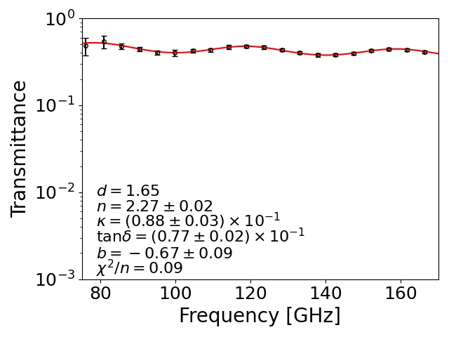
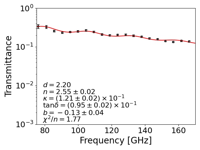
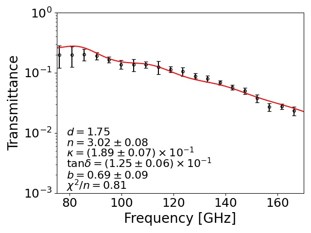
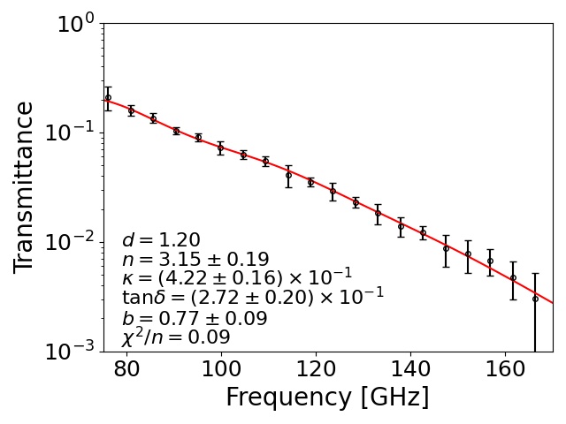
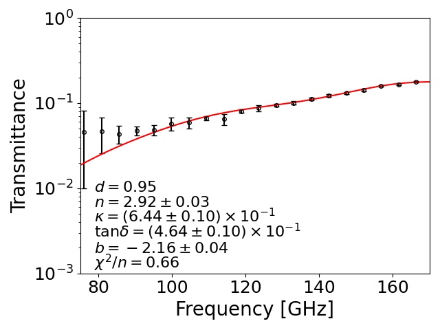
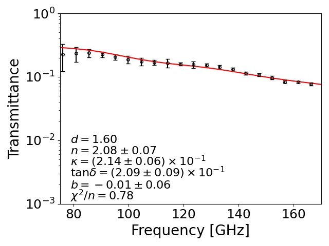
To understand and for each sample, we made flat-shaped samples, as shown in Fig. 4 (h). We measured their transmittance at low temperature as well as at room temperature. We used a Martin–Puplett-type Fourier transform spectrometer (FTS) with a semiconducting bolometer Ohta, Hattori, and Matsuo (2006); Ohta et al. (2007). The transmittance was obtained by the ratio of measured powers with and without the sample. For the low-temperature measurements, we took the ratio of the data for a liquid nitrogen bath itself without the sample and the data for the sample set in this bath. Figure 5 shows the transmittance at 77 K for STYCAST-2850FT, and the samples doped with additional absorptive materials: stainless steel, graphite, two types of carbon fibers, and carbon nanotube.
The transmittance is modeled with the following formulas,
| (2a) | |||||
| (2b) | |||||
| (2c) | |||||
| (2d) | |||||
Here, is the complex index of refraction for each sample. The is an ordinary index of refraction of air or liquid nitrogen. Note that the extinction coefficients of air and liquid nitrogen are negligible. We allowed for the fact that the has a frequency dependence by adding the parameter . For , we did not observe any frequency dependence within the accuracy of our measurements. We extracted , , and by a fitting to the measured transmittance using the above formulas. We fixed the thickness () because it was measured by using a caliper for each sample with an accuracy of . We also fixed for the room temperature (liquid nitrogen temperature) measurement.
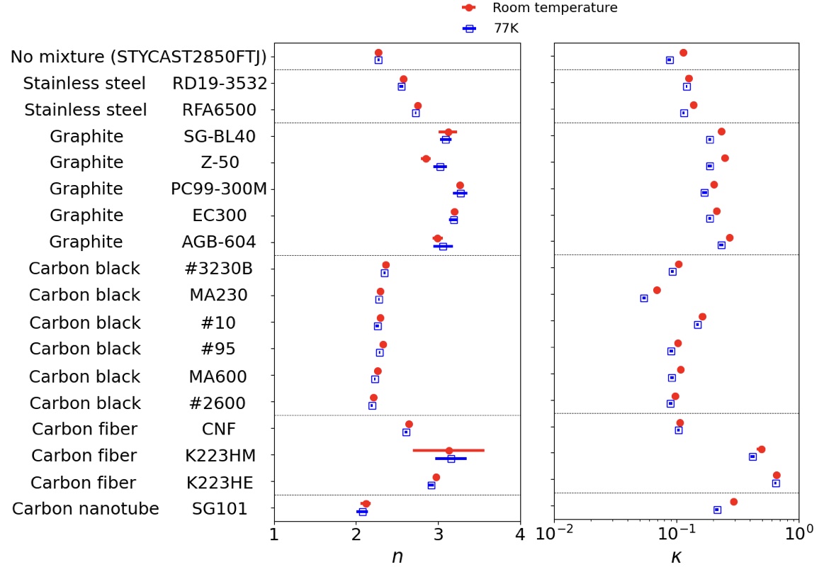
Extracted optical parameters for each sample at each temperature condition are summarized in Fig. 6 and Table 2. We found that the two samples that contained the carbon fibers, K223HE and K223HM, achieved a large . These were significantly higher than the sample using stainless steel (RD19-3532), which is currently used for the CMB project Ade et al. (2019). There was no significant difference for between the two temperature conditions. However, the at 77 K was lower than the value at room temperature for most of the samples. The difference of between 77 K and room temperature was small () for three samples: the stainless steel powder (RD19-3532) and two types of carbon fibers (CNF and K223HE).
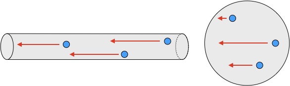
In Table 2, extracted parameters had two types of error: statistical uncertainty (middle values for each row) and systematic uncertainty (right values for each row). The statistical errors were assigned with the standard deviations of 20 times the FTS measurements. For several samples, we also measured the transmittance using a vector network analyzer (VNA). We observed a difference of linearity for the response between the FTS measurement and the VNA measurement. Therefore, we conservatively assigned the effect of this linearity difference as the systematic error. The sample whose particle size was large tended to have a high . One of possible interpretations is that is related to the mean free path of the free electrons in the material. The absorption of radio waves is dependent on the electrical conductivity of the material. The sample doped with large particles had a long mean free path of the electron. In particular, the two carbon fibers, K223HM and K223HE, had a large . This is because the particle shape of these fibers is a long cylinder, and the mean free path of the electron is significantly longer than the cases with the other materials (Fig. 7). The carbon nanotubes are predisposed to clumping. This property resulted in a shorter mean free path of the electron than for the cases of the carbon fibers.
IV Reflectance of selected materials
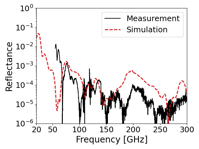
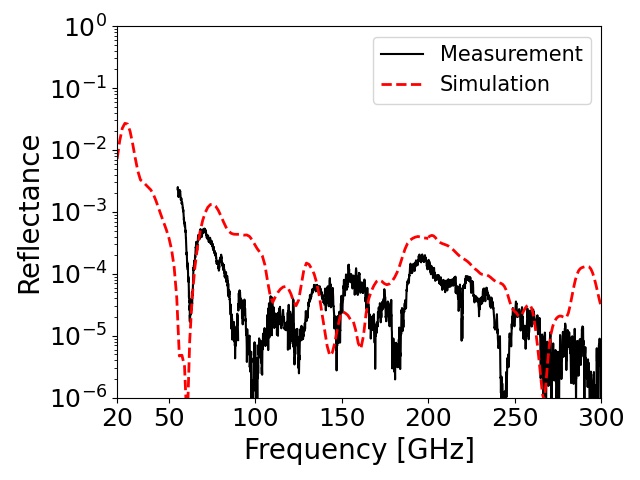
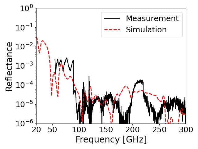
We fabricated four RAM-3pm with the selected materials: the stainless steel powder (RD19-3532), two carbon fibers (K223HM and K223HE), and the carbon nanotube (SG101). We measured their reflectance using the VNA in the frequency range of 50–300 GHz at room temperature. The incident signal was polarized perpendicular to the incident plane (S-polarized). Its incident angle to the RAM sample was , and the direction of the reflection signal was .
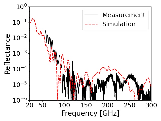
Figure 8 shows the measured reflectance for each RAM-3pm. In the range of 70–300 GHz, all of the samples achieved a low reflectance below . However, we observed the difference among the samples in the 50–70 GHz range. The two samples made with K223HE or SG101 maintained a low reflectance, while the others did not. We confirmed the statement described in the section II and Fig. 3; the reflectance relies on at the frequency range below 70 GHz.
We also performed a simulation based on the configuration of the VNA measurements. We used the measured parameters from the previous section, i.e., and at the room temperature. The simulation results are overlaid on the measured reflectance, as shown in Fig. 8. They were broadly similar to the VNA measurements. Even below 50 GHz, the two samples mixed with K223HE or K223HM still maintained a low reflectance () according to the simulation.
V Discussion
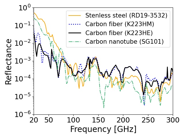
To understand the performance in a cryogenic application, we also simulated the reflectance at 77 K by using the measured parameters in the liquid nitrogen bath. In this simulation study, we used the unpolarized signal as the real application. We also included the scattered signal in any direction as well as the specular reflectance in the direction. Figure 9 shows the simulation results for each candidate materials in frequency range of 20–300 GHz.
A difference in the achieved reflectance among the four materials was noticeable below 70 GHz. This tendency was implied by the room temperature study in the previous section. The RAM-3pm made with the carbon fiber K223HE achieved the best performance. This material also satisfied our requirement except at the lower edge of the frequency range (20 GHz). For the RAM-3pm made with carbon nanotube SG101, we observed a significant increase of the reflectance owing to the degradation of at 77 K.
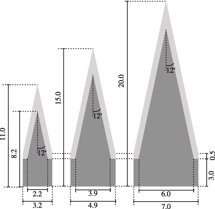
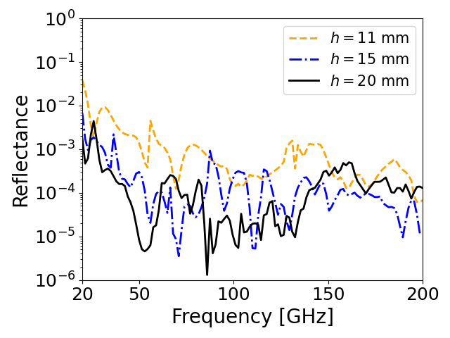
To improve the reflectance around 20 GHz, we optimized the surface structure of the RAM-3pm. Figure 10 shows simulation results with changing the height of the pyramidal structure. We obtained a reflectance below 1% when we double its height. We also simulated the case of changing the thickness behind the pyramids. However, this did not result in any improvement.
VI Conclusions
We previously established the method to fabricate a radio absorptive material by using a 3D-printed mold, which is named as RAM-3pm. The wide range of choices for materials is the advantage of this method compared with the other methods. In this paper, we survey the best material for the RAM-3pm. We set the requirement for the reflectance towards a CMB application: in the wide frequency range of 20–300 GHz and in a cryogenic condition. We select four materials based on the measured optical parameters ( and ) from 17 materials. We made four RAM-3pm for each absorptive material, and we measured the reflectance for each of them at the room-temperature condition. We confirm that the simulation results are broadly similar to the measurements.
We also simulate the reflectance at the low-temperature condition using the optical parameters obtained in the liquid nitrogen bath. We conclude that the RAM-3pm made with the mixture of STYCAST-2850FT and carbon fiber K223HE achieves the best performance. This satisfies our requirement except for around the 20 GHz range.
We discuss how to improve the reflectance by changing the surface structure of the RAM-3pm. We estimate that it is possible to achieve a reflectance below 1% in the frequency range of 20–300 GHz when we double the height of the pyramidal structure. These estimations will be confirmed by using an improved system for the reflectance measurement at 20–50 GHz. Understanding the performance at even lower temperatures () is also a future project.
Acknowledgements
We thank Toyo Aluminium K.K., Ito Graphite Co. Ltd., Mitsubishi Chemical Corp., ALMEDIO INC., Zeon Nano Technology Co. Ltd., Henkel AG Co. KGaA, EC Engineering K.K., and CEMEDINE CO. LTD. for providing us with the absorptive materials which were used in this paper. This work is supported by JSPS KAKENHI under grant numbers JP17H06134 and JP21H00071, and also supported by World Premier International Research Center Initiative (WPI), MEXT, Japan. TO acknowledges the JSPS core-to-core program JPJSCCA20200003 for his travel supports. SA also acknowledges JP18J01039. We thank Tomotake Matsumura and Edanz (https://jp.edanz.com/ac) for editing a draft of this manuscript.
Data Availability
The data that support the findings of this study are available from the corresponding author upon reasonable request.
References
- Ade et al. (2019) P. Ade et al., “The simons observatory: science goals and forecasts,” Journal of Cosmology and Astroparticle Physics 2019, 056–056 (2019).
- Adachi et al. (2020) S. Adachi, M. Hattori, F. Kanno, K. Kiuchi, T. Okada, and O. Tajima, “Production method of millimeter-wave absorber with 3d-printed mold,” Review of Scientific Instruments 91, 016103 (2020), https://doi.org/10.1063/1.5132871 .
- Xu et al. (2021) Z. Xu, G. E. Chesmore, S. Adachi, A. M. Ali, A. Bazarko, G. Coppi, M. Devlin, T. Devlin, S. R. Dicker, P. A. Gallardo, J. E. Golec, J. E. Gudmundsson, K. Harrington, M. Hattori, A. Kofman, K. Kiuchi, A. Kusaka, M. Limon, F. Matsuda, J. McMahon, F. Nati, M. D. Niemack, A. Suzuki, G. P. Teply, R. J. Thornton, E. J. Wollack, M. Zannoni, and N. Zhu, “The simons observatory: metamaterial microwave absorber and its cryogenic applications,” Appl. Opt. 60, 864–874 (2021).
- Petroff et al. (2019) M. Petroff, J. Appel, K. Rostem, C. L. Bennet t, J. Eimer, T. Marriage, J. Ramirez, and E. J. Wollack, “A 3d-printed broadband millimeter wave absorber,” Review of Scientific Instruments 90, 024701 (2019), https://doi.org/10.1063/1.5050781 .
- (5) ANSYS, Inc., Southpointe, 2600 Ansys Drive, Canonsburg, PA 15317, USA, https://www.ansys.com/ .
- Jackson (1999) J. D. Jackson, Classical electrodynamics, 3rd ed. (Wiley, New York, NY, 1999).
- (7) Henkel Japan Ltd., 14F Sphere Tower Tennozu, 2-2-8 Higashi Shinagawa, Shinagawa-ku, Tokyo, 140-0002, Japan, https://www.henkel.com .
- (8) Toyo Aluminium K.K., 6-8, Kyutaromachi 3-chome, Chuo-ku, Osaka 541-0056 JAPAN, https://www.toyal.co.jp/eng/ .
- (9) Ito Graphite Co., Ltd., 970, Tado-chou Tado, Kuwana-shi, Mie 511-0106 JAPAN, http://www.graphite.co.jp/index.html .
- (10) Mitsubishi Chemical Corporation, 1-1 Marunouchi 1-chome, Chiyoda-ku, Tokyo 100-8251, Japan, http://www.carbonblack.jp/en/index.html .
- (11) ALMEDIO INC., KS Kunitachi Bld. 7F,1-4-12, Higashi,Kunitachi-shi, Tokyo,186-0002, Japan, https://www.almedio.co.jp/en/ .
- (12) Mitsubishi Chemical Corporation , 1-1 Marunouchi 1-chome, Chiyoda-ku, Tokyo 100-8251, Japan, https://www.m-chemical.co.jp/en/products/departments/mcc/cfcm/product/1201229_7502.html .
- (13) Zeon Nano Technology Co., Ltd., Shin Marunouchi Center Building 14th Floor, 1-6-2 Marunouchi, Chiyoda-ku, Tokyo Japan, http://www.zeonnanotech.jp/en/index.html .
- Ohta, Hattori, and Matsuo (2006) I. S. Ohta, M. Hattori, and H. Matsuo, “Development of a multi-Fourier-transform interferometer: fundamentals,” Appl. Opt. 45, 2576–2585 (2006).
- Ohta et al. (2007) I. S. Ohta, M. Hattori, Y. Chinone, Y. Luo, Y. Hamaji, J. Takahashi, H. Matsuo, and N. Kuno, “Astronomical testing observation in multi-Fourier transform interferometer: Aperture synthesis technique and CMB,” in 2007 Joint 32nd International Conference on Infrared and Millimeter Waves and the 15th International Conference on Terahertz Electronics (2007) pp. 335–336.