Log-linear Dynamic Inversion Control with Provable Safety Guarantees in Lie Groups
Abstract
In this paper, we use the derivative of the exponential map to derive the exact evolution of the logarithm of the tracking error for mixed-invariant systems, a class of systems capable of describing rigid body tracking problems in Lie groups. Additionally, we design a log-linear dynamic inversion-based control law to remove the nonlinearities due to spatial curvature and enhance the robustness of the controller. We apply Linear Matrix Inequalities (LMIs) to bound the tracking error given a bounded disturbance amplified by the distortion matrix and leverage the tracking error bound to create flow pipes. To demonstrate the usefulness of our method, we show its application with Urban Air Mobility (UAM) scenarios using a simplified kinematic aircraft model and polynomial-based path planning methods.
Index Terms:
Lie Group Theory, Mixed-Invariant Systems, Log-Linearization, Dynamic Inversion Control, Safety VerificationI Introduction
Ensuring the safety of an Unmanned Aerial System (UAS) in urban environments is a challenging task as a UAS operates in a dynamic environment subject to unknown uncertainties, such as wind, etc. [1]. One of the approaches to ensure the safety of a dynamical system is to construct an invariant set of system trajectories in the presence of unknown disturbances. An invariant set represents the set of trajectories in which the system remains if it starts within or enters the set [2, 3, 4]. This notion of set invariance provides a powerful tool to analyze the worst-case impact of the unknown disturbance on the system.
For constructing invariant sets, the existing methods in the literature either use a grid-based [5, 6, 7] or a Lyapunov function-based approach [8, 9]. One of the recent methods in the grid-based approach is FaStrack [7], where the Hamilton-Jacobi (HJ) reachability of the error dynamics between a tracking system and a planning system is computed. The authors have successfully demonstrated that when the control authority is powerful, the tracking error is bounded, and the HJ partial differential equations (PDEs) converge. Another popular method for constructing invariant sets of nonlinear systems is using a Lyapunov function [8]. A Lyapunov function can be found either by hand or using a Lyapunov-based control design methodology, such as backstepping control [10, 9, 11]. While the HJ reachability approach can compute the invariant set for a nonlinear system, it is computationally expensive. Similarly, Lyapunov-based approaches for non-linear systems can be tedious and difficult to generalize. In this work, we utilize Linear Matrix Inequalities (LMIs) [12] to efficiently compute the invariant set of the linearized error dynamics of the nonlinear tracking system.
For a class of nonlinear systems, group affine systems [13], whose states can be represented using Lie Groups, a unique property, the log-linear property, can be employed to convert the nonlinear structure of the Lie Group into a linear form in the Lie algebra. Modeling the states of the nonlinear system as a member of a Lie group has been successfully applied in various applications such as state estimation [13], motion control [14], optimal control [15, 16, 17], etc. In the Lie algebra, a group affine system [13] behaves linearly despite nonlinearities in the original system on the Lie group, such as those arising from rigid body rotation. The Lie algebra provides a convenient coordinate system using the log-linear property for the log-linearization of error dynamics, where the number of coordinates is equal to the degrees of freedom of the dynamical system. However, the log-linear property of the error dynamics governing the deviation of a system from its reference trajectory does not hold in the presence of feedback control, disturbance, and noise, which can cause nonlinearities in the Lie algebra dynamical system. These nonlinearities are often neglected in existing work on log-linearized systems [13, 18]. As a result, the exact solution is not provided, and thus the computed invariant set of the nonlinear dynamics is over-approximated.
This paper presents a generalized method for deriving the exact evolution of the log-linearization of the error dynamics for mixed-invariant systems, as defined in [19], in Lie groups using the derivative of the exponential map. While a similar method is mentioned in [20], where they derive the log-linearization without approximation for a specific Lie group, , our work was developed independently, we provide the exact log-linearization approach applicable to any Lie group, making our method more generic. Additionally, to enhance the control robustness, we propose a log-linear dynamic inversion-based control law. To illustrate the effectiveness of our method, we demonstrate the application in a UAM scenario example with a kinematics aircraft model in the Lie group. This example involves calculations of invariant sets and the creation of flow pipes.
In this paper, our contributions are as follows:
-
1.
We derive the exact evolution for the log-linearization of the error dynamics of mixed-invariant systems with disturbance and control input in the vehicle system for any Lie group.
-
2.
We design a log-linear dynamic inversion-based control law to enhance the robustness of the control system.
-
3.
We derive a series-form of the nonlinear input distortion matrix, , for any Lie group, and compute a closed-form of for the Lie group, which is the Special Euclidean group of two-dimensional rigid body rotation and translation.
-
4.
We formulate flow-pipe computation for a kinematic aircraft model by using our log-linear dynamic inversion-based control strategy and applying LMIs to calculate the invariant sets.
The rest of this paper is organized as follows. The preliminary background and problem formulation are presented in Section II. In Section III, we use the derivative of the exponential map in the Lie group to derive the exact log-linearization for the error dynamics of mixed-invariant systems, and design the log-linear dynamic inversion controller using the log-linearized system in the Lie algebra. In Section IV, we embed the two-dimensional kinematic aircraft model in the Lie group, and show an example of log-linearization in the Lie group with disturbances. In Section V, we illustrate the simulation results for our kinematic aircraft model. Finally, in Section VI, we present our concluding remarks and immediate future works.
II Preliminaries and Problem Statement
II-A Background and Preliminaries
Definition 1.
(Mixed-Invariant System [19]) The left-invariant system [21, 19, 17] in the Lie group has the form of , and the right-invariant system in the Lie group is , where is a Lie group whose associated Lie algebra is denoted and represents states of the systems. are inputs of the systems and may be functions of time, and are elements in the Lie algebra, which define the left- and right-invariant vector fields, respectively. denotes the wedge operator that maps elements from to the Lie algebra . If a system is the summation of a left-invariant system and a right-invariant system, , then the system is called a mixed-invariant system.
Definition 2.
Lemma 2.
(The Derivative of the Exponential Map [23]) The exponential map of a matrix Lie group is a map from the matrix Lie algebra to the corresponding matrix Lie group, . The derivative of the exponential map is given by:
| (1) |
Here, denotes the identity element of the group, which is the identity matrix for matrix Lie groups [23, 24], is the adjoint representation of in the Lie algebra, and .
Based on the log-linear property, we can log-linearize the nonlinear system with feedback control, bounded disturbance, and noise to an exact linear bounded input system using the derivative of the exponential map. The invariant set for the linear bounded input system can be found efficiently employing LMIs.
II-B Problem Formulation
Consider the dynamics of two mixed-invariant vector fields, where is the state of the vehicle and is the state of the reference trajectory:
| (2) | ||||
where are inputs of the systems and may be functions of time. The relationship between the two inputs is . is the deviation of the system from the reference left-invariant vector field, , and is the deviation of the system from the reference right-invariant vector field, . The left- and right-invariant errors, are defined as follows [13]:
| (3) |
In this paper, we are interested in deriving the exact log-linearization for the error dynamics, , of mixed-invariant systems, and designing a robust controller with provable safety guarantees.
III Main Result
In this section, we first derive the exact log-linearization for the error dynamics of mixed-invariant systems for both left- and right-invariant error dynamics. We then design a log-linear dynamic inversion control law to address the nonlinear input distortion and enhance the robustness of the system.
III-A Exact Log-Linearization of Mixed-Invariant System
Theorem 1.
(Logarithm of Left-Invariant Error Dynamics) For the systems in 2, denote the left-invariant error by , then the logarithm of the left-invariant error dynamics, , is governed by the differential equation:
| (4) | ||||
where is the state vector of the left-invariant error dynamics in the Lie algebra, is the adjoint representation of in the Lie group, and is the matrix of nonlinear input distortion of inputs in the Lie algebra for the left-invariant error dynamics. A proof is provided in Appendix A.
Theorem 2.
(Logarithm of Right-Invariant Error Dynamics) For the systems in 2, denote the right-invariant error by , then the logarithm of the right-invariant error dynamics, , is governed by the differential equation:
| (5) | ||||
where is the state vector of right-invariant error dynamics in the Lie algebra, and is the adjoint representation of input in the Lie algebra. is the matrix of nonlinear input distortion of inputs in the Lie algebra for the right-invariant error dynamics. The proof can be derived with the same process as the proof of 4 in Appendix A.
III-B Log-Linear Dynamic Inversion Control
For control, 4 and 5 suggest a direct approach for dynamic inversion of the log-linearized mixed-invariant vector field dynamics. We will focus on 4 but this can also be extended to 5.
Theorem 3.
(Log-Linear Dynamic Inversion Control) Given the dynamics in 4 with and , where represents a control input and represents a disturbance input, if is designed as:
| (6) |
where is the control input matrix, and is the corresponding gain matrix for the state feedback controller.
When using dynamic inversion control, it is important to determine if inputs are saturated in the controller. Since we use a state feedback control law, this can be efficiently checked and verified using the invariant set of the states.
Lemma 3.
(Stability of the Log-Linearized System with Log-Linear Dynamic Inversion Control Law) Since the log-linearized system in the Lie algebra is a linear system with BIBO stability, a Lyapunov function can be found using LMIs and used to compute an invariant set to which the system is globally asymptotically stable (GAS).
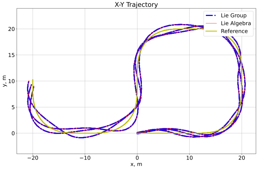
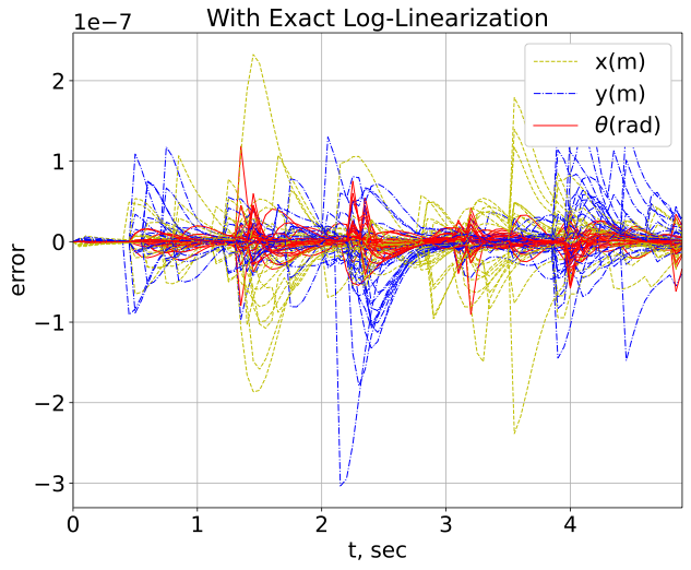
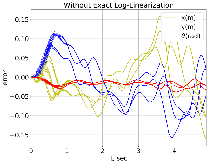
Figure 1 shows a 2D example of the bijection between the vehicle trajectories in the Lie group and the Lie algebra, which are simulated with sinusoidal disturbances of fixed magnitude at varying frequencies. In order for a bijection to exist, the exponential map must be injective and surjective, which holds if the domain of the Lie algebra is restricted to [24]. Effectively meaning that our control law will disregard multiple rotations, which is the intended behaviour. If the invariant set in the Lie algebra extends beyond the domain of , this would indicate a possibly instability through a continuous spinning motion. Thus, the LMI approach is invalidated, as the linear dynamics do not consider the angle wrapping. The figure on the left in Fig. 2 shows that the log-linearized system dynamics in the Lie algebra do not deviate from the closed loop mixed-invariant system dynamics when the exact log-linearization is applied (the shown deviation can be arbitrarily reduced using numerical tolerances); however, there are significant deviations from the closed loop mixed-invariant system if our log-linearization is not applied (figure on the right). Therefore, we numerically demonstrate 4 and 5 by showing that a bijection exists between the trajectories in the Lie group and Lie algebra even in the presence of disturbance and control feedback, given a domain sufficiently close to the reference trajectory (e.g. avoiding angle wrapping). This is a useful result, as the Lie algebra is a vector space that is more convenient for analysis than the Lie group which is a nonlinear manifold [24].
IV Example: Kinematic Aircraft Model in the Lie Group
In the UAM system, we consider vehicles with 3D rigid body rotation and translation, the Lie group. For constant altitude flight, this can be simplified to 2D rigid body rotation and translation, the Lie group. Since both VTOL and fixed-wing UAS dynamics can be well approximated as differentially flat [27, 28], we can calculate a reference trajectory that is flyable by the aircraft with negligible error in the absence of disturbance and noise. This is important as our approach focuses on the deviation of the aircraft from this reference trajectory. To simplify our approach in this paper, we consider a constant altitude kinematic model of the UAS with bounded disturbances to account for modelling error, which simplifies the UAS kinematics to a two-dimensional holonomic model. Although we are limiting our analysis to the Lie group, our algebraic approach can be generalized to other Lie groups [29] (e.g., the Lie Group of rigid body rotation and translation in three dimensions).
IV-A Lie Group Embedded Vehicle Kinematics
Consider the kinematic aircraft model evolving on a 2D plane, as follows:
| (8) |
where denotes the heading angle, and denote the position. represents the angular velocity, and represent the forward and side translational velocity respectively. We assume our kinematic aircraft model as a holonomic model due to the side-slip angle of the aircraft and mentioned in [27].
The kinematic aircraft model in 8 can be embedded in the Lie group in 9, a matrix Lie group. Special in the Special Euclidean group indicates that all matrices have determinant . A Lie group is a group that is also a smooth manifold. The associated Lie algebra is a vector space tangent to the Lie group at the identity [30]. A Lie group and its Lie algebra are closely related, which allows calculations in one to be mapped into the other. The exponential map maps the Lie algebra to the Lie group and the logarithm map, the inverse of the exponential map, maps the Lie group to the Lie algebra [24].
The corresponding left-invariant system dynamics [14, 15, 19, 17] of the 2D holonomic aircraft problem, which is a mixed-invariant system with the right-invariant vector field, , equal to zero, is given by:
| (9) |
where represents the state of the 2D holonomic aircraft in the Lie group. Note that may be a function of time and represents the input of the vehicle, including feedback control and disturbances. The Lie group may be represented by matrices of the form:
| (10) |
where , which is an element of the 2D rotation group, and . The Lie group is a semi-direct product of the and [24].
The corresponding Lie algebra, may be represented by matrices of the form:
| (11) |
where is the element in the Lie algebra. is the corresponding skew-symmetric matrix of , such that , . In Lie group theory, the adjoint representation [24] transports a Lie algebra element from one tangent space to another. Here, for an element of the Lie algebra, we use to represent the adjoint in the Lie algebra, which can be written as:
| (12) |
IV-B Log-Linearization in the Lie Group
The 2D kinematics aircraft kinematics can be embedded in the Lie group as . We also consider the reference kinematics embedded in the Lie group differential equation, as , where denotes the state of the reference trajectory, and denotes the input of the reference trajectory, and may be functions of time to account for non-trivial reference trajectories.
As we mention in the previous section, the relationship between and is , here, we consider , where is the feedback control input, and is the disturbance. The left-invariant error between our kinematic aircraft model and the reference kinematics is . From 4 and 6, the error dynamics in the Lie algebra can be written as:
| (13) |
where and .
For the Lie group, the inverse of the nonlinear input distortion matrix, , can be written in a series-form function and a closed-form matrix, which is found by reducing the sine and cosine series:
| (14) |
where and . The determinant of is , since we limit , the determinant will never be zero, is always invertible. Therefore, the closed-form matrix of for the Lie group is:
| (15) |
where and .
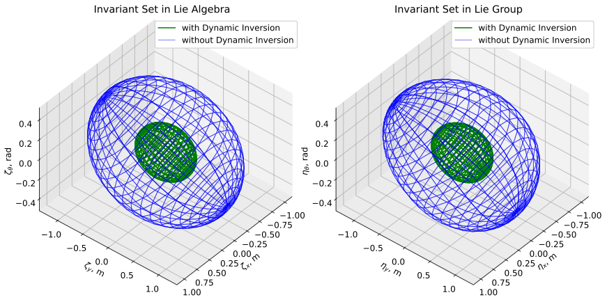
The invariant set for a system can be calculated by finding an upper bound for the singular value of the nonlinear input distortion matrix, , over the invariant set. The nonlinear input distortion, , depends on the error state, . If there exists an invariant set, since the invariant set is a set of the error states, will depend on the invariant set itself. And the calculation of the invariant set also depends on the singular value of , we propose a Log-linear LMI-based iterative method to compute the invariant set in Algorithm 1. An invariant set calculated by this algorithm is shown in Figure 3.
V Simulation Studies of Kinematic Aircraft Model
In this section, we consider an illustrative UAM scenario where a fixed-wing aircraft flies along a reference trajectory at a constant altitude. The reference trajectory is generated by polynomial trajectory planning [28, 31, 32]. We consider a kinematic model of the fixed-wing aircraft. Our model is given by the equations in 8, which can be embedded in the Lie group, 9. The log-linear error dynamics between the vehicle model and the reference model in the Lie algebra are given in 13. For the external disturbances in the direction, we assume rad/s. For disturbances in the direction, we consider two different disturbance magnitudes. We assume the magnitude of the bounded disturbance inputs, , as m/s and m/s, respectively.
V-A Invariant Set
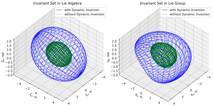
Since the inputs of the reference trajectory may be functions of time, we use the LMI to calculate the invariant set for a linear polytopic system with bounded disturbances [12]. The bounds of the inputs to calculate the invariant set are based on the bounds of the reference inputs, where m/s, m/s, and rad/s. We use the Linear-Quadratic-Regular (LQR) method to find the feedback controller for the log-linearized system in the Lie algebra. After employing our iterative method, Algorithm 1, to find the desired maximum singular value of , the final result of the invariant set in the Lie algebra and the Lie group is shown in Fig. 3. The figures show the invariant set with small initial states in the Lie group, . The invariant set in the Lie group is constructed by applying the exponential map from the set in the Lie algebra.
If the control input does not employ dynamic inversion, the control input in 6 becomes , and the error dynamics in the Lie algebra in 13 can be rewritten as:
| (16) |
Here, we use the example to compare the difference between the two controllers. For the control input without dynamics inversion, we consider the nonlinear term of the control input as a bounded input in the LMI calculation. Blue lines in Fig. 3 show the result of the invariant set for the controller without dynamic inversion. Since the nonlinear term of the control input is considered a bounded input, the invariant set has a larger tracking error bound than the controller with dynamic inversion. Comparing the invariant sets in Fig. 3, we can see that the invariant set is approximately twice as large in the case of the control input without dynamic inversion compared to the case with dynamic inversion. Therefore, the invariant set has a smaller tracking error bound with our designed controller.
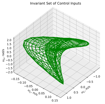
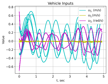
The Lyapunov function in the LMI approach is an ellipsoid, which is the shape of the invariant set for the log-linearized system in the Lie algebra as shown on the left of Fig. 3 with green lines. The invariant sets in the Lie group, which are mapped from the invariant sets in the Lie algebra using the exponential map, are shown on the right of Fig. 3 with green lines. Since the invariant set in the Lie group is not an ellipsoid after mapping, as shown in Fig. 3, and is in the vehicle body frame; therefore, the invariant set must be rotated along the trajectory to create flow pipes. The left figure in Fig. 4 shows the invariant set of our log-linear dynamic inversion control inputs for the small disturbance case, the saturation bounds for each direction are m/s, m/s, and rad/s. The right figure in Fig. 4 shows the time history plot of the control inputs for the simulated trajectories with sinusoidal and square wave disturbances in the small disturbance case, and each control input stays within the saturation bound for all time.
V-B Flow Pipes
To verify the safety properties for the UAM mission, we construct flow pipes along a reference trajectory. Any Lyapunov function will be sufficient for our method and we follow a general approach of the flow pipes creation in [4]. To construct the flow pipe, we first propagate the reference trajectory using polynomial trajectory planning for a fixed time interval and compute the interval hull of the reference trajectory. The interval hull is the smallest box enclosing the set for the propagation duration. Since our invariant set depends on the direction of the reference trajectory, we sweep the invariant set from the minimum rotational angle to the maximum rotational angle in that time interval. Using the swept invariant set and interval hull, we then compute the convex hull for the flow pipe segment using the Minkowski sum [33]. Therefore, the flow pipe for the trajectory can be constructed by repeating the above processes for the next time interval.
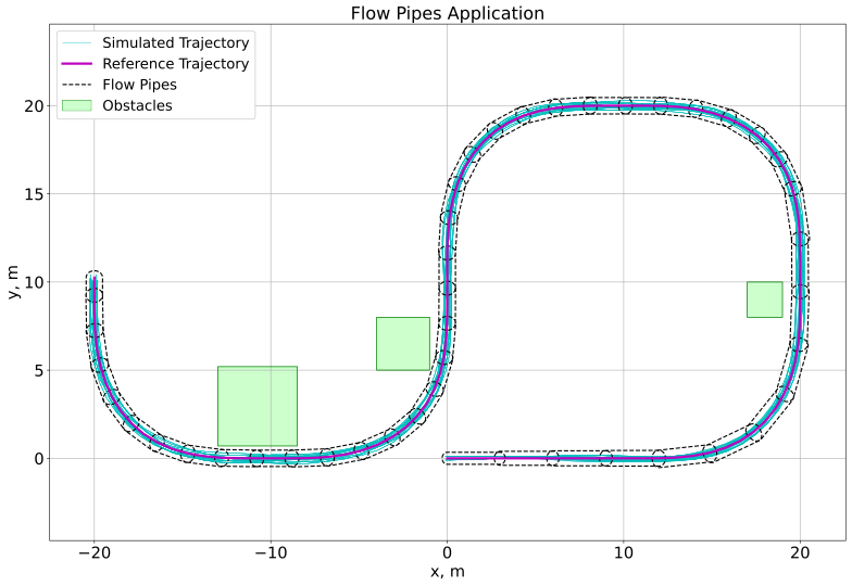
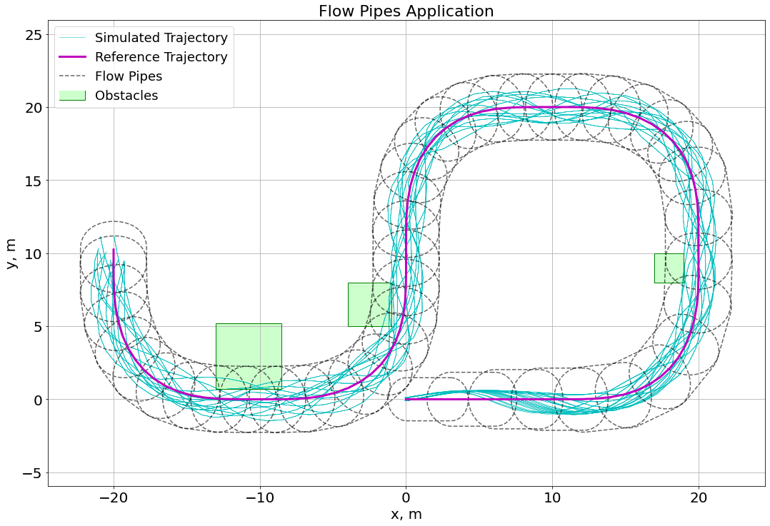
Figure 5 shows the application of flow pipes to the UAM problem. The green squares represent collision zones or obstacles (e.g., buildings) that the vehicle needs to avoid. Here, we simulate both sinusoidal and square wave wind disturbances. We simulate two different scenarios for the vehicle. The first scenario is simulated with small wind disturbances with a magnitude of m/s, which is shown at the top of Fig. 5. We can see that the green collision zones, obstacles, and the flow pipes do not intersect; therefore, we can confirm the safety of the vehicle, since the simulation shows that the vehicle won’t hit the buildings during the mission. Another scenario is simulated with large wind disturbances with a magnitude of m/s, which is shown at the bottom of Fig. 5. We can see that the buildings and the flow pipes are now intersecting. Therefore, we are able to confirm that it is not safe for the vehicle to conduct the mission with wind disturbances of this magnitude. We can also see that some simulated trajectories collide with obstacles and the mission is therefore unsafe.
VI Conclusion
In this paper, we presented a novel approach to derive the exact log-linearization of the error dynamics of mixed-invariant systems. This approach employed the derivative of the exponential map in Lie group theory. Our analysis of the evolution of the log-linearized system yielded a nonlinear input distortion matrix. We were able to leverage the singular value of this bounded input distortion matrix to reformulate our tracking error dynamics to a linear system with bounded-input bounded-output (BIBO) stability. Additionally, we designed a new dynamic inversion-based control law to simplify the log-linearized tracking error dynamics to a linear system with a bounded disturbance and enhanced the robustness of the system. In the simulation, we demonstrated the application of our algorithm to safety verification in an Urban Air Mobility (UAM) scenario. We also compared the bound of the invariant set with and without the dynamic inversion-based control law.
As future work, we intend to consider the invariant set as time-varying to narrow the bound of the flow pipes and extend our approach to more complex aircraft dynamic models with the and Lie groups.
Appendix A Proof of 4
Using the product rule, the left-invariant error dynamics, which are the derivative of , can be written as:
| (17) | ||||
Let , where is the left-invariant error in the Lie algebra. Based on Lemma 2, the derivative of the exponential map can be written as:
| (18) |
The left-invariant error dynamics in 17 can be rewritten as:
| (19) |
The corresponding dynamics for left-invariant error in the Lie algebra can be derived as:
| ∧ | (20) | |||
can be expressed as a matrix power series of , and is a linear operator on the Lie algebra, therefore, we can use the Lie vee operator, , which is the inverse of the wedge operator, to map the error dynamics from a form of elements of the Lie algebra 20 to elements of the vector space 4 as shown in 4.
Let , since each term in this expression is a power of , multiplication is commutative, thus, , using the taylor series of exponential, we can find a series form for :
| (21) | ||||
References
- [1] D. P. Thipphavong, R. Apaza, B. Barmore, V. Battiste, B. Burian, Q. Dao, M. Feary, S. Go, K. H. Goodrich, J. Homola et al., “Urban air mobility airspace integration concepts and considerations,” in 2018 AIAA Aviation Technology, Integration, and Operations Conference, 2018, p. 3676.
- [2] A. Chutinan and B. H. Krogh, “Verification of polyhedral-invariant hybrid automata using polygonal flow pipe approximations,” in International workshop on hybrid systems: computation and control. Springer, 1999, pp. 76–90.
- [3] A. Chutinan and B. Krogh, “Computational techniques for hybrid system verification,” IEEE Transactions on Automatic Control, vol. 48, no. 1, pp. 64–75, 2003.
- [4] J. M. Goppert, “Security and verification of unmanned vehicles,” Ph.D. dissertation, Purdue University Graduate School, 2019.
- [5] I. M. Mitchell, A. M. Bayen, and C. J. Tomlin, “A time-dependent hamilton-jacobi formulation of reachable sets for continuous dynamic games,” IEEE Transactions on automatic control, vol. 50, no. 7, pp. 947–957, 2005.
- [6] T. Homer and P. Mhaskar, “Constrained control lyapunov function-based control of nonlinear systems,” Systems & Control Letters, vol. 110, pp. 55–61, 2017.
- [7] M. Chen, S. L. Herbert, H. Hu, Y. Pu, J. F. Fisac, S. Bansal, S. Han, and C. J. Tomlin, “Fastrack: a modular framework for real-time motion planning and guaranteed safe tracking,” IEEE Transactions on Automatic Control, vol. 66, no. 12, pp. 5861–5876, 2021.
- [8] H. Khalil, Nonlinear Systems, ser. Pearson Education. Prentice Hall, 2002.
- [9] Z. Wang, X. Liu, K. Liu, S. Li, and H. Wang, “Backstepping-based lyapunov function construction using approximate dynamic programming and sum of square techniques,” IEEE transactions on cybernetics, vol. 47, no. 10, pp. 3393–3403, 2016.
- [10] P. Kokotović and M. Arcak, “Constructive nonlinear control: a historical perspective,” Automatica, vol. 37, no. 5, pp. 637–662, 2001.
- [11] M. Tayefi and Z. Geng, “Logarithmic control, trajectory tracking, and formation for nonholonomic vehicles on lie group se (2),” International Journal of Control, vol. 92, no. 2, pp. 204–224, 2019.
- [12] S. Boyd, L. El Ghaoui, E. Feron, and V. Balakrishnan, Linear matrix inequalities in system and control theory. SIAM, 1994.
- [13] A. Barrau and S. Bonnabel, “The invariant extended kalman filter as a stable observer,” IEEE Transactions on Automatic Control, vol. 62, no. 4, pp. 1797–1812, 2016.
- [14] N. E. Leonard and P. S. Krishnaprasad, “Motion control of drift-free, left-invariant systems on lie groups,” IEEE Transactions on Automatic control, vol. 40, no. 9, pp. 1539–1554, 1995.
- [15] A. M. Bloch, P. E. Crouch, J. E. Marsden, and A. K. Sanyal, “Optimal control and geodesics on quadratic matrix lie groups,” Foundations of Computational Mathematics, vol. 8, pp. 469–500, 2008.
- [16] M. B. Kobilarov and J. E. Marsden, “Discrete geometric optimal control on lie groups,” IEEE Transactions on Robotics, vol. 27, no. 4, pp. 641–655, 2011.
- [17] L. J. Colombo and D. V. Dimarogonas, “Symmetry reduction in optimal control of multiagent systems on lie groups,” IEEE Transactions on Automatic Control, vol. 65, no. 11, pp. 4973–4980, 2020.
- [18] S. Teng, W. Clark, A. Bloch, R. Vasudevan, and M. Ghaffari, “Lie algebraic cost function design for control on lie groups,” in 2022 IEEE 61st Conference on Decision and Control (CDC). IEEE, 2022, pp. 1867–1874.
- [19] A. Khosravian, J. Trumpf, R. Mahony, and T. Hamel, “State estimation for invariant systems on lie groups with delayed output measurements,” Automatica, vol. 68, pp. 254–265, 2016.
- [20] X. Li, H. Jiang, X. Chen, H. Kong, and J. Wu, “Closed-form error propagation on {} group for invariant ekf with applications to vins,” IEEE Robotics and Automation Letters, vol. 7, no. 4, pp. 10 705–10 712, 2022.
- [21] C. Lageman, J. Trumpf, and R. Mahony, “Gradient-like observers for invariant dynamics on a lie group,” IEEE Transactions on Automatic Control, vol. 55, no. 2, pp. 367–377, 2009.
- [22] A. Barrau and S. Bonnabel, “Invariant particle filtering with application to localization,” in 53rd IEEE Conference on Decision and Control. IEEE, 2014, pp. 5599–5605.
- [23] W. Rossmann, Lie groups: an introduction through linear groups. Oxford University Press on Demand, 2006, vol. 5.
- [24] B. Hall, Lie groups, Lie algebras, and representations: an elementary introduction. Springer, 2015, vol. 222.
- [25] K. A. Pant, L.-Y. Lin, J. Goppert, and I. Hwang, “Towards robust state estimation in matrix lie groups,” in Workshop on Geometric Representations, ICRA IEEE,, 2023.
- [26] M. Dahleh, M. A. Dahleh, and G. Verghese, “Lectures on dynamic systems and control,” A+ A, vol. 4, no. 100, pp. 1–100, 2004.
- [27] J. Levine, Analysis and control of nonlinear systems: A flatness-based approach. Springer Science & Business Media, 2009.
- [28] D. Mellinger and V. Kumar, “Minimum snap trajectory generation and control for quadrotors,” in 2011 IEEE international conference on robotics and automation. IEEE, 2011, pp. 2520–2525.
- [29] L.-Y. Lin, J. Goppert, and I. Hwang, “Application of log-linear dynamic inversion control to a multi-rotor,” in Workshop on Geometric Representations, ICRA IEEE,, 2023.
- [30] A. Baker, Matrix groups: An introduction to Lie group theory. Springer Science & Business Media, 2012.
- [31] C. Richter, A. Bry, and N. Roy, “Polynomial trajectory planning for aggressive quadrotor flight in dense indoor environments,” in Robotics research. Springer, 2016, pp. 649–666.
- [32] K. M. Lynch and F. C. Park, Modern robotics. Cambridge University Press, 2017.
- [33] G. Varadhan and D. Manocha, “Accurate minkowski sum approximation of polyhedral models,” in 12th Pacific Conference on Computer Graphics and Applications, 2004. PG 2004. Proceedings. IEEE, 2004, pp. 392–401.