Lagrangian dynamics and regularity of the spin Euler equation
Abstract
We derive the spin Euler equation for ideal flows by applying the spherical Clebsch mapping. This equation is based on the spin vector rather than the velocity. It enables a feasible Lagrangian study of fluid dynamics, as the isosurface of a spin-vector component is a vortex surface and material surface in ideal flows. The spin Euler equation is also equivalent to a special case of the Landau–Lifshitz equation with a specific effective magnetic field, revealing a possible connection between ideal flow and magnetic crystal. We conduct direct numerical simulations of three ideal flows of the vortex knot, vortex link and modified Taylor–Green flow by solving the spin Euler equation. The evolution of the Lagrangian vortex surface illustrates that the regions with large vorticity are rapidly stretched into spiral sheets. We establish a non-blowup criterion for the spin Euler equation, suggesting that the Laplacian of the spin vector must diverge if the solution forms a singularity at some finite time. The DNS result exhibits a pronounced double-exponential growth of the maximum norm of Laplacian of the spin vector, showing no evidence of the finite-time singularity formation if the double-exponential growth holds at later times. Moreover, the present criterion with Lagrangian nature appears to be more sensitive than the Beale–Kato–Majda criterion in detecting the flows that are incapable of producing finite-time singularities.
keywords:
vortex dynamics, topological fluid dynamics1 Introduction
The dynamics of an ideal flow is governed by the three-dimensional (3D) incompressible Euler equation. One of the outstanding open problems in fluid mechanics is whether smooth initial data can lead to finite-time singularities in the ideal flow. This problem is closely related to the existence and smoothness of solutions to the Navier–Stokes (NS) equation (e.g. Fefferman, 2001; Doering, 2009; Wei, 2016; Ayala & Protas, 2017).
The regularity of the incompressible Euler equation has been extensively studied. Various criteria for blowup and non-blowup, based on different quantities and techniques, have been reviewed by Chae (2008), Gibbon (2008) and Drivas & Elgindi (2022). Several criteria relate the occurrence of singularity to the growth of the vorticity which plays a vital role in fluid dynamics. The Beale–Kato–Majda (BKM) criterion establishes a sufficient condition for the regularity in terms of (Beale et al., 1984). The geometric criterion of Constantin et al. (1996) relates the regularity of the velocity to the smoothness of the vorticity direction. Moreover, there are some refined analytical criteria for blowup (e.g. Planchon, 2003; Zhou & Lei, 2013).
The regularity of the incompressible Euler equations has also been investigated by large-scale numerical simulations. Brachet et al. (1983, 1992) and Bustamante & Brachet (2012) conducted numerical studies of the evolution of the inviscid Taylor–Green (TG) flow, and showed a near-exponential growth of the maximum vorticity over time, with regions of the high vorticity predominantly confined within thin, sheet-like structures. The formation of vortex sheets reduces the three-dimensionality, which suppresses the formation of a finite-time singularity (Constantin et al., 1996; Drivas & Elgindi, 2022).
As the regularity of the 2D Euler equations was established (Pumir & Siggia, 1990; Majda & Bertozzi, 2002; Ohkitani, 2008), subsequent numerical studies primarily focused on the carefully designed initial condition that would enhance the vorticity growth. However, different vorticity growth trends were observed in the numerical simulations with different initial conditions or even the same initial condition.
For the two perturbed anti-parallel vortex tubes, Kerr (1993, 2005) found which provided a strong evidence in favour of blowup, whereas Hou & Li (2007) and Hou (2009) obtained a high-resolution numerical solution that is still regular beyond the presumed blowup time and exhibited a maximum vorticity growth slower than double-exponential. The analysis was subsequently revisited in Bustamante & Kerr (2008) which proposed a hypothesis of a vorticity growth of with , and in Kerr (2013) which reported a double-exponential growth.
The vorticity growth of was also observed in Grauer et al. (1998) using a perturbed cylindrical shear flow, and in Orlandi et al. (2012) using the collision of two Lamb dipoles. Agafontsev et al. (2015, 2017) reported that the vorticity grows exponentially in time in a shear flow with random perturbations. Moreover, Ricca et al. (1999) suggested that the vortex knot is a useful configuration for studying singularity formation, and also pointed out the lack of study on the evolution of vortex knots or links with finite thickness in ideal flows.
Several studies examined the Kida–Pelz (KP) flow (Kida, 1985; Boratav & Pelz, 1994; Pelz, 2001), which is another highly symmetric flow for investigating the formation of potential finite-time singularity. Grafke et al. (2008) compared different numerical methods applied to a KP flow in spectral and real spaces, and found no evidence of blowup at the times predicted by previous studies, which was confirmed by Hou & Li (2008). They also observed that the vorticity increases exponentially along the Lagrangian trajectory.
Furthermore, there are several studies which are not based on the Euler equation for investigating potential finite-time singularities in ideal flows. Campolina & Mailybaev (2018) developed a model identical to the Euler equations by imitating the calculus on a 3D logarithmic lattice. This model for ideal flows elucidates the emergence of singularities as a manifestation of a chaotic attractor in a renormalized dynamical system. Their results implied that the direct numerical simulation (DNS) with the available resolution is inadequate for the analysis of singularity formation for the Euler equation. By employing a level-set representation for the vorticity field, Constantin (2001a, b) and Deng et al. (2005) established global existence theorems for a wide range of initial values and revealed the geometric structures of plausible blowup scenario, for the 3D Euler equations and the 3D Lagrangian averaged Euler equations.
In the present study, we apply the spherical Clebsch mapping (Kuznetsov & Mikhailov, 1980) to develop the spin Euler equation, which is equivalent to the original Euler equation, but its form has an inherent Lagrangian nature for tracking vortex surfaces. We study the Lagrangian dynamics and regularity of the spin Euler equation with the DNS of various inviscid vortical flows, and derive a new non-blowup condition for the spin Euler equation.
The outline of the present paper is as follows. Section 2 introduces the spin Euler equation and derives the non-blowup condition. Section 3 describes numerical set-ups and methods. Section 4 elucidates Lagrangian dynamics of ideal flows and assesses the non-blowup criterion. Some conclusions are drawn in § 5.
2 Theoretical framework of the spin Euler equation
2.1 Introduction of the spin Euler equation
The 3D incompressible Euler equation is
| (1) |
with , where is the velocity and the pressure.
By applying the spherical Clebsch mapping (Kuznetsov & Mikhailov, 1980), (1) is transformed into a Lagrangian form
| (2) |
Here, the spin vector (Chern et al., 2016; Chern, 2017) is linked with a two-component wave function by the Hopf fibration (Hopf, 1931)
| (3) |
with , and the imaginary unit . Then, the velocity and vorticity can be re-expressed by and
| (4) |
respectively, where is the Levi–Civita symbol. Note that even though an arbitrary in (4) may have no globally smooth spin vector due to vorticity nulls (Graham & Henyey, 2000) and unclosed vortex lines, a useful approximation can be obtained using the regularizer (Chern et al., 2017) and the Poincaré recurrence theorem (Poincaré, 1890).
We consider the quaternion form of the two-component wave function , where , , and are real-valued functions and are the basis vectors of the imaginary part of the quaternion. The velocity and spin vector are then given by and , respectively, where denotes the quaternion conjugate of . Then, we derive
| (5) |
where is a pure quaternion (i.e. a vector in ) and can be expanded as with
| (6) |
Thus, we rewrite with an effective field .
In general, cannot be represented solely in terms of , because the Hopf mapping is irreversible. Nevertheless, using the generalised Biot–Savart (BS) law, we can compute at any point in from the distribution of under various boundary conditions, as illustrated in figure 1.
Substituting (5) into (2), we obtain the spin Euler equation
| (7) |
It is equivalent to the original incompressible Euler equation (1). In contrast to (2), (7) characterises the evolution of by its precession about rather than the convection with . The spin Euler equation (7) can be more suitable to study fluid dynamics from a Lagrangian perspective than its original form (1), because the isosurfaces of are vortex surfaces consisting of vortex lines (Yang & Pullin, 2010, 2011; Yang et al., 2023). From the Helmholtz theorem, the surfaces are material surfaces for all in Euler flows.
Therefore, solving the spin Euler equation (7) is similar to a vortex method (Yang et al., 2021; Nabizadeh et al., 2022; Xiong et al., 2022) for simulating ideal flows. Since the primary variable of (7) is a unit vector, the simulation of the spin Euler equation could avoid issues of numerical blowup.
In particular, the spin Euler equation contains the inherent Lagrangian vortex dynamics via level sets of (i.e. vortex surfaces). This can facilitate the regularity analysis of the Euler equation, similar to the level set representation of (Constantin, 2001a, b; Deng et al., 2005).
It is also interesting that the spin Euler equation (7) can be considered as the Landau–Lifshitz equation
| (8) |
without a damping term (Landau & Lifshitz, 1935), which is used to analyse magnetodynamic processes in magnetic materials, and is generally referred to as the Heisenberg model (Lakshmanan & Porsezian, 1990; Porsezian & Lakshmanan, 1991; Kamppeter et al., 2001). The Landau–Lifshitz equation plays an important role in elucidating magnetisation dynamics, analogous to the role of the NS equation in fluid dynamics.
The mean spin of electrons, i.e. the magnetisation (or spin vector) at the macroscopic scale, determines the unit volume magnetic dipole moment in magnetic crystals. A continuous function describes the macroscopic magnetisation dynamics in the limit of vanishing lattice partition size, if the angle between the spin vectors of neighbouring lattice atoms in a crystal is sufficiently small (Heisenberg, 1928). This resembles the continuum assumption in fluid mechanics, but unlike isotropic fluids, most crystal structures are anisotropic.
In (8), is the effective magnetic field, corresponding to (minus) the -derivative of the magnetic energy of the material with respect to . This implies a deep connection between the ideal flow and magnetic material. The spin Euler equation has , where the magnetic energy of a material is replaced by the total kinetic energy of a fluid. Therefore, the ideal flow might be physically interpreted as a specific magnetic material by (7). As sketched in figure 2, the magnetisation (or spin) in (3) at each point in space precesses around the effective magnetic field in (6).
2.2 Non-blowup condition of the spin Euler equation
Next, we discuss the regularity of the spin Euler equation. By taking the double inner-product of and the gradient of (7), and multiplying , we obtain
| (9) |
where is a constant, and the vector product of the second-order tensor and the vector is defined as with the basis . Using the identity for the unit vector , we have
| (10) |
Integrating (9) over an unbounded domain or a domain bounded by solid wall boundaries and using (10) yield
| (11) |
where the Neumann boundary condition is imposed on the solid wall boundary. Applying the Hölder inequality to (11) yields
| (12) |
Here, the -norm of a function is defined as
| (13) |
We estimate the upper bound of in terms of . From (4), using and basic inequalities, we obtain
| (14) |
so that
| (15) |
Then, we estimate the upper bound of in terms of and . Substituting (14) into (6), we have
| (16) |
so that
| (17) |
Integrating (17) over the domain yields
| (18) |
By virtue of the Sobolev–Poincaré inequality (Moffatt & Tsinober, 1992),
| (19) |
holds, with a positive constant independent of . Combining (10), (15), (18) and (19), we derive
| (20) |
Finally, substituting (20) into (12) and applying the Hölder inequality, we have
| (21) |
where is the finite measure of domain . Integrating (21) over time yields
| (22) |
for , with a constant , and
| (23) |
for .
As the Hölder inequality leads to
| (24) |
we have
| (25) |
where is a finite coefficient when . Using (15), (22) and (25), the -norm of the vorticity can be estimated by
| (26) |
Moreover, using (15), (23) and (25), the -norm () of the vorticity can be estimated by
| (27) |
From (26) and (27), we obtain a sufficient condition for bounded as
| (28) |
Note that it is straightforward to deduce the special case of (28) with from (14) using the BKM theorem (Beale et al., 1984).
In summery, we obtain a non-blowup condition (28) of the spin Euler equation (which is equivalent to the original Euler equation), which guarantees a bounded . It implies that, if the solution loses regularity beyond a certain time, the Laplacian of the spin vector must grow unbounded. The transport equation and the estimation of the norm of are further discussed in Appendix B.
3 Simulation overview
We conduct the DNS of three ideal flows with different initial conditions in a periodic cube of side on (up to ) uniform grid points, by solving the spin Euler equation
| (29) |
with the pseudo-spectral method. Here, denotes the wavenumber vector, is a smooth initial condition, and is the Fourier transform operator with its inverse form . The high-order Fourier smoothing method (Hou & Li, 2007) is used to suppress the Gibbs phenomenon. The temporal evolution is integrated using an explicit second-order Runge–Kutta scheme with adaptive time steps in physical space. The time step is selected to ensure that the Courant–Friedrichs–Lewy number is smaller than 0.3 for numerical stability and accuracy.
We consider two types of initial conditions. For the first type, the initial vorticity is concentrated in a thin closed vortex tube, such as the trefoil knot (Yao et al., 2021; Zhao & Scalo, 2021; Zhao et al., 2021) and Hopf link (Aref & Zawadzki, 1991; Kivotides & Leonard, 2021; Yao et al., 2022). Under the self-induced velocity, such vortex tubes can be gradually stretched, twisted and flattened, and form nearly singular vortical structures.
We use the rational map (Kedia et al., 2016; Tao et al., 2021) to construct smooth . A small twist is applied to the vortex tube by setting (Tao et al., 2021), and and are chosen for the trefoil knot and the Hopf link, respectively. Here, are a pair of complex polynomial functions and is a mapping of the coordinate system from the Euclidean space to the two-component complex space . The function pair is normalised and subjected to a divergence-free projection, yielding in a two-component wave function that matches the initial field. The initial spin vector and vorticity are then obtained from (3) and (4), respectively. Additionally, we re-scale the time as with the initial mean length and the circulation . The trefoil knot has and , and the Hopf link has and .
The second type is a modified Taylor–Green (MTG) initial condition (Meng & Yang, 2023), with smooth
| (30) |
and
| (31) |
The re-scaling time is . This highly symmetric MTG flow would not exhibit a finite-time singularity, and this non-blowup case is used to validate the criterion in (28). The parameters for all cases are listed in table 1.
| Cases | |||||||
| Trefoil knot | up to | ||||||
| Hopf link | up to | ||||||
| MTG | up to | – | – |
To evaluate the numerical resolution, we define , the ratio of the minimum resolved scale to the grid spacing . A finer resolution has a larger . The evolution of for the three initial conditions is shown in figure 3(a–c). Our numerical tests suggest that can be the criterion for well resolving the smallest scale of (29). The largest numbers of grid points in the simulation are for the trefoil knot and the Hopf link, and for the MTG flow. Based on the criterion, the largest time of the simulation with the satisfactory resolution is given in table 1 for each case.

Additionally, the resolution can be assessed by the conservation of the total energy and the helicity (Moreau, 1961; Moffatt, 1969; Meng et al., 2023), which are two invariants of the Euler equations. The energy loss is less than 1‰ for in figures 3(d–f), and the helicity is also well conserved in figures 3(g–i).
4 Evolution of the spin Euler equation
4.1 Evolution of vortex surfaces
The DNS of the spin Euler equation (7) is carried out to investigate Lagrangian dynamics of ideal flows listed in table 1, and to validate the non-blowup criterion (28). To illustrate the Lagrangian vortex dynamics, figure 4 shows the top view of the isosurface of (i.e. vortex surface) for the trefoil knot at , 0.9 and 1.8. Note that isosurfaces of and can show similar structures (Tao et al., 2021), and the isosurfaces of (not shown) fail to capture the complete vortex tube as visualised by (as discussed in Xiong & Yang, 2019; Shen et al., 2023) .
Near the three crossings of the initial vortex knot, adjacent parts of the vortex tube are nearly orthogonal. Driven by the self-induced velocity with the BS law, the vortex tube and vortex lines are stretched and twisted. The adjacent parts of the vortex knot approach each other, and they are progressively flattened and rolled up, instead of undergoing the vortex reconnection in viscous flows (Yao & Hussain, 2022). The regions with large vorticity magnitude are rapidly stretched into spiral sheets with strong twist.
In figure 4, the evolving vortex surfaces and lines preserve their initial mapping to the red circle and cyan points on , respectively, due to the Lagrangian nature of the spin Euler equation. Namely, the vortex topology is preserved in ideal flows. In addition, figure 5 shows the top view of the isosurface of for the Hopf link at , 0.88, and 2.19. The structural evolution is similar to that of the trefoil knot.
Figure 6 plots the contour of on the – plane at and on the – plane at for the trefoil knot, along with the contour lines of . These planes intersect the point with the largest , so their contours show the most intense swirling motion. In figure 6(b), ‘vorticity pancakes’ (Brachet et al., 1992) form in the regions of large among highly stretched and curved vortex surfaces. These structures appear when the vortex surfaces approach each other and undergo strong deformation. The formation of the high-vorticity region within sheet-like structures was observed in the collapse of vortex pairs (e.g. Pumir & Siggia, 1990; Kerr, 1993) and TG and KP flows (Yang & Pullin, 2010). Furthermore, we observe the energy spectra with the scaling (not shown) in the evolution of the trefoil knot and Hopf link, consistent with the result for the collision of two Lamb dipoles in Orlandi et al. (2012).
In the highly symmetric MTG flow, a finite-time singularity may not exhibit according to the theoretical analysis (Constantin et al., 1996). Figure 7 plots the evolution of the isosurfaces of (red) and (blue) for the MTG flow. A pair of vortex blobs are compressed and flattened into pancakes. Since the vortex surface is compressed in a quasi-2D configuration, preserving the smoothness of the vorticity direction (Constantin et al., 1996), the MTG flow does not exhibit a finite time singularity, even though the vorticity grows rapidly (Brachet et al., 1992).
The comparison of the two types of ideal flows implies that the Euler equation cannot form a singularity in a 2D process. Constantin et al. (1996) proved that if remains uniformly bounded and stays , then no singularity can occur. In other words, the vorticity must change its direction very rapidly to form a potential singularity. Note that if a singularity occurs at a vorticity null for all (e.g. Elgindi, 2021), the vorticity direction becomes discontinuous at the time of singularity. The MTG flow vortex lines near the vorticity nulls maintain a quasi-2D smooth shape, which contradicts the necessary blowup conditions. Hence, the MTG flow does not exhibit finite-time singularities. By contrast, the trefoil knot or Hopf link have large vortex-line curvature in figures 4(c) and 5(c) with a rapid change in the vorticity direction.
4.2 Assessment of the non-blowup criterion
We apply (28) to the three ideal flows to test the non-blowup criterion based on the spin Euler equation, and compare our criterion to the BKM criterion (Beale et al., 1984) by examining growth rates of the maximum vorticity and Laplacian spin vector. Before , increases by a factor of about 16 for the trefoil knot and the Hopf link in figure 8. Both and exhibit the nearly double-exponential growth for the trefoil knot and Hopf link. The double-exponential growth of is consistent with the results in Hou & Li (2007) and Kerr (2013). As the number of grid points increases (up to ), the growth rate of appears to remain constant for the trefoil knot and Hopf link.
The present criterion has some advantages that grows more slowly than (4–6 times slower), and exhibits better convergence with the mesh resolution. Therefore, can be resolved more easily than with the same numerical accuracy. Moreover, the duration of the linear stage for exceeds that for by more than a factor of five.
The highly symmetric MTG flow shows no evidence of a finite time singularity. The profile of in figure 8(f) clearly bends downward before with . The growth rate of is weaker than double exponential, whereas the growth of remains double exponential in figure 8(c) when . Therefore, the criterion based on can effectively identify the flows that are unlikely to develop a finite-time singularity.
As the double-exponential growth is bounded in a finite time , we have
| (32) |
with constants and . According to the non-blowup condition (28), the Euler equation can avoid singularity formation in finite time for the double-exponential growth of .

4.3 Difference of non-blowup criteria
We highlight the major difference between (28) and the BKM criterion, and explain why grows more slowly than . Figure 9 plots the trajectories of and colour-coded by and their projections on the – plane for the trefoil knot and Hopf link. The trajectories of and starting from the same locations do not collapse, implying that the present criterion is distinct from the BKM criterion.
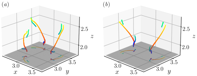
The continuous trajectory of is more tractable than the discontinuous one of in figure 9. Figure 10 illustrates the -coordinates of the maximum and , the Lagrangian trajectory of particles which locate at the position of the maximum values at , and the evolution of the centroid positions of the trefoil knot and Hopf link. We find that remains continuous over time and moves at a constant speed in the -direction in both flows, which is close to the Lagrangian velocity of the particle at the location of (or ) at . This implies that the maximum could have some Lagrangian nature.

By contrast, exhibits a sharp jump at for the trefoil knot and for the Hopf link. The speed of in the -direction is close to that of the centroid of the vortex at early times. During the surge of , it jumps to a value close to (marked in dashed box in figure 10).
We examine the correlation and distribution of the values of and , normalised by their respective maxima, for the trefoil knot at and the Hopf link at . The scatter plots in figure 11 shows a low positive correlation between and , with correlation coefficients of for the trefoil knot and for the Hopf link. Therefore, the criterion based on in (28) has a notable statistical difference from that based on .

The probability density function (PDF) of the normalised values of and for the trefoil knot at and the Hopf link at is shown in figure 12. For both configurations, the PDF profiles of are smoother than those of , and they obey a Pareto distribution (Arnold, 2015) with the power law except for very large values, indicating that the extreme values at a few locations can dominate norms of and .

5 Conclusions
We develop a new framework for describing ideal flows using the spin Euler equation (7). The spin Euler equation can be considered as a special Landau–Lifshitz equation with an effective magnetic field in (6), implying a possible connection between the ideal flow and magnetic material.
The spin Euler equation provides a feasible approach to study Lagrangian fluid dynamics, because the isosurfaces of a spin-vector component are vortex surfaces and material surfaces for all . In particular, we derive a non-blowup condition (28) for the spin Euler equation – if the solution becomes singular at some finite time, then must become unbounded.
We conduct the DNS of three ideal flows of the trefoil knot, Hopf link and MTG by solving (29) using the pseudo-spectral method, and compare the BKM criterion with the present one. The evolution of the vortex surface (isosurface of ) illustrates that the regions with large are rapidly stretched into spiral sheets for the trefoil knot and Hopf link.
For the trefoil knot and Hopf link, the double-exponential growth of is more pronounced than that of , and grows at a rate 4–6 times slower than . The duration of the double-exponential growth stage for exceeds that for by more than five times. According to the non-blowup condition (28), the Euler equation can avoid the singularity formation at finite time if the growth rate of is lower than double exponential at late times.
The highly symmetric MTG flow can avoid finite-time singularities due to the formation of quasi-2D vortex surfaces from theoretical analysis (Constantin et al., 1996). The growth rate of is lower than double exponential at late times, whereas the growth rate of remains double exponential. Thus, the present criterion based on appears to be more sensitive than the BKM criterion based on in detecting the flows that are incapable of producing finite-time singularities.
The present non-blowup criterion based on is distinct from the BKM criterion based on . By tracing the maxima of and for vortex knots and link, we find that the trajectory for is continuous and consistent with the tracer particle, benefited from the Lagrangian nature of the spin Euler equation. In contrast, the trajectory for with a large jump deviates from the Lagrangian trajectory. Furthermore, and only has a low positive correlation coefficient.
In the future work, the bound estimate of requires further refinement, and the duration in the simulation can be prolonged with more computational resources for examining longer growth behaviour of . Furthermore, the spin Euler equation can be recast as a nonlinear Schrödinger equation that is useful in quantum computing of fluid dynamics (Meng & Yang, 2023).
Acknowledgments
The authors thank S. Xiong for the helpful discussion. Numerical simulations were carried out on the TH-2A supercomputer in Guangzhou, China.
Funding
This work has been supported by the National Natural Science Foundation of China (Grant Nos. 11925201 and 11988102), the National Key R&D Program of China (Grant No. 2020YFE0204200), and the Xplore Prize.
Declaration of interests
The authors report no conflict of interest.
Author contributions
Y.Y. and Z.M. designed research. Z.M. preformed research. Y.Y. and Z.M. discussed the results and wrote the manuscript. All the authors have given approval for the manuscript.
Appendix A Comparison of the spin Euler system and the isotropic Heisenberg spin system
We discuss the similarity and difference between the spin Euler system in (7) and the isotropic Heisenberg spin system in (8) with . After some algebra, we find
| (33) |
where the term
| (34) |
highlights the difference between the spin Euler system and the Heisenberg spin system. Projecting onto yields
| (35) |
i.e. the angle between and is acute or normal.
As sketched in figure 13, the range of the angle between and depends on the spin system. The isotropic Heisenberg spin system has with
| (36) |
whereas the spin Euler system has with
| (37) |
Presuming is directed to the north pole, in the isotropic Heisenberg spin system is confined to the southern hemisphere, whereas there is no such restriction in the spin Euler system due to the additional term . Therefore, the spin Euler system for ideal flows can have greater degrees of freedom and more complex dynamics than the isotropic Heisenberg spin system for magnetic crystals.
Appendix B Upper bound estimation for
We show an attempt on estimating the upper bound of which is an important ingredient in the non-blowup criterion in (28). Taking the inner product of and the Laplacian of (7) yields the evolution equation for
| (38) |
Integrating (38) over yields
| (39) |
Applying the Hölder inequality to (39) we obtain
| (40) |
which yields
| (41) |
Integrating (41) over time yields
| (42) |
with constants
| (43) |
The inequality (42) implies a closure problem in the bound estimation – the growth of the -norm of depends on its higher order derivatives. In addition, using the identity
| (44) |
we estimate the growth rate of the -norm of
| (45) |
However, it appears to be challenging to estimate and in terms of . Thus, the estimations of (42) and (45) need to be improved in the future work.
References
- Agafontsev et al. (2015) Agafontsev, D. S., Kuznetsov, E. A. & Mailybaev, A. A. 2015 Development of high vorticity structures in incompressible 3D Euler equations. Phys. Fluids 27, 085102.
- Agafontsev et al. (2017) Agafontsev, D. S., Kuznetsov, E. A. & Mailybaev, A. A. 2017 Asymptotic solution for high-vorticity regions in incompressible three-dimensional Euler equations. J. Fluid Mech. 813, R1.
- Aref & Zawadzki (1991) Aref, H. & Zawadzki, I. 1991 Linking of vortex rings. Nature 354, 50–53.
- Arnold (2015) Arnold, B. C. 2015 Pareto Distribution, pp. 1–10. John Wiley & Sons, Ltd.
- Ayala & Protas (2017) Ayala, D. & Protas, B. 2017 Extreme vortex states and the growth of enstrophy in three-dimensional incompressible flows. J. Fluid Mech. 818, 772–806.
- Beale et al. (1984) Beale, J. T., Kato, T. & Majda, A. 1984 Remarks on the breakdown of smooth solutions for the 3-D Euler equations. Commun. Math. Phys. 94, 61–66.
- Boratav & Pelz (1994) Boratav, O. N. & Pelz, R. B. 1994 Direct numerical simulation of transition to turbulence from a high-symmetry initial condition. Phys. Fluids 6, 2757–2784.
- Brachet et al. (1983) Brachet, M. E., Meiron, D. I., Orszag, S. A., Nickel, B. G., Morf, R. H. & Frisch, U. 1983 Small-scale structure of the taylor–green vortex. J. Fluid Mech. 130, 411–452.
- Brachet et al. (1992) Brachet, M. E., Meneguzzi, M., Vincent, A., Politano, H. & Sulem, P. L. 1992 Numerical evidence of smooth self-similar dynamics and possibility of subsequent collapse for three-dimensional ideal flows. Phys. Fluids A 4, 2845–2854.
- Bustamante & Brachet (2012) Bustamante, M. D. & Brachet, M. 2012 Interplay between the Beale–Kato–Majda theorem and the analyticity-strip method to investigate numerically the incompressible Euler singularity problem. Phys. Rev. E 86, 066302.
- Bustamante & Kerr (2008) Bustamante, M. D. & Kerr, R. M. 2008 3D Euler about a 2D symmetry plane. Physica D: Nonlinear Phenomena 237, 1912–1920.
- Campolina & Mailybaev (2018) Campolina, C. S. & Mailybaev, A. A. 2018 Chaotic blowup in the 3D incompressible Euler equations on a logarithmic lattice. Phys. Rev. Lett. 121, 064501.
- Chae (2008) Chae, D. 2008 Incompressible Euler equations: the blow-up problem and related results. In Handbook of Differential Equations: Evolutionary Equations (ed. C. M. Dafermos & M. Pokorny), , vol. 4, pp. 1–55. Elsevier.
- Chern (2017) Chern, A. 2017 Fluid dynamics with incompressible Schrödinger flow. Phd thesis, California Institute of Technology, Pasadena, CA.
- Chern et al. (2017) Chern, A., Knöppel, F., Pinkall, U. & Schröder, P. 2017 Inside fluids: Clebsch maps for visualization and processing. ACM Trans. Graph. 36, 1–11.
- Chern et al. (2016) Chern, A., Knöppel, F., Pinkall, U., Schröder, P. & Weißmann, S. 2016 Schrödinger’s smoke. ACM Trans. Graph. 35, 1–13.
- Constantin (2001a) Constantin, P. 2001a An Eulerian–Lagrangian approach for incompressible fluids: Local theory. J. Am. Math. Soc. 14, 263–278.
- Constantin (2001b) Constantin, P. 2001b An Eulerian–Lagrangian approach to the Navier–Stokes equations. Commun. Math. Phys. 216, 663–686.
- Constantin et al. (1996) Constantin, P., Fefferman, C. & Majda, A. J. 1996 Geometric constraints on potentially singular solutions for the 3-D Euler equations. Commun. Partial Differ. Equ. 21, 559–571.
- Deng et al. (2005) Deng, J., Hou, T. Y. & Yu, X. 2005 A level set formulation for the 3D incompressible Euler equations. Methods Appl. Anal. 12, 427–440.
- Doering (2009) Doering, C. R. 2009 The 3D Navier–Stokes Problem. Annu. Rev. Fluid Mech. 41, 109–128.
- Drivas & Elgindi (2022) Drivas, T. D. & Elgindi, T. M. 2022 Singularity formation in the incompressible Euler equation in finite and infinite time, arXiv: 2203.17221.
- Elgindi (2021) Elgindi, T. M. 2021 Finite-time singularity formation for solutions to the incompressible Euler equations on . Ann. Math. 194, 647–727.
- Fefferman (2001) Fefferman, C. 2001 Existence and smoothness of the Navier–Stokes equation.
- Gibbon (2008) Gibbon, J. D. 2008 The three-dimensional Euler equations: Where do we stand? Physica D 237, 1894–1904.
- Grafke et al. (2008) Grafke, T., Homann, H., Dreher, J. & Grauer, R. 2008 Numerical simulations of possible finite time singularities in the incompressible Euler equations: Comparison of numerical methods. Physica D 237, 1932–1936.
- Graham & Henyey (2000) Graham, C. R. & Henyey, F. S. 2000 Clebsch representation near points where the vorticity vanishes. Phys. Fluids 12, 744–746.
- Grauer et al. (1998) Grauer, R., Marliani, C. & Germaschewski, K. 1998 Adaptive mesh refinement for singular solutions of the incompressible Euler equations. Phys. Rev. Lett. 80, 4177.
- Heisenberg (1928) Heisenberg, W. 1928 Zur Theorie des Ferromagnetismus. Z. Phys. 49, 619–636.
- Hopf (1931) Hopf, H. 1931 Über die Abbildungen der Dreidimensionalen Sphäre auf die Kugelfläche. Math. Ann. 104, 637–665.
- Hou (2009) Hou, T. Y. 2009 Blow-up or no blow-up? A unified computational and analytic approach to 3D incompressible Euler and Navier–Stokes equations. Acta Numer. 18, 277–346.
- Hou & Li (2007) Hou, T. Y. & Li, R. 2007 Computing nearly singular solutions using pseudo-spectral methods. J. Comput. Phys. 226, 379–397.
- Hou & Li (2008) Hou, T. Y. & Li, R. 2008 Blowup or no blowup? The interplay between theory and numerics. Physica D 237, 1937–1944.
- Kamppeter et al. (2001) Kamppeter, T., Leonel, S. A., Mertens, F. G., Gouvêa, M. E., Pires, A. S. T. & Kovalev, A. S. 2001 Topological and dynamical excitations in a classical 2D easy-axis Heisenberg model. Eur. Phys. J. B 21, 93–102.
- Kedia et al. (2016) Kedia, H., Foster, D., Dennis, M. R. & Irvine, W. T. M. 2016 Weaving knotted vector fields with tunable helicity. Phys. Rev. Lett. 117, 274501.
- Kerr (1993) Kerr, R. M. 1993 Evidence for a singularity of the three-dimensional, incompressible Euler equations. Phys. Fluids A 5, 1725–1746.
- Kerr (2005) Kerr, R. M. 2005 Velocity and scaling of collapsing Euler vortices. Phys. Fluids 17, 075103.
- Kerr (2013) Kerr, R. M. 2013 Bounds for Euler from vorticity moments and line divergence. J. Fluid Mech. 729, R2.
- Kida (1985) Kida, S. 1985 Three-dimensional periodic flows with high-symmetry. J. Phys. Soc. Jpn. 54, 2132–2136.
- Kivotides & Leonard (2021) Kivotides, D. & Leonard, A. 2021 Helicity spectra and topological dynamics of vortex links at high Reynolds numbers. J. Fluid Mech. 911, A25.
- Kuznetsov & Mikhailov (1980) Kuznetsov, E. A. & Mikhailov, A. V. 1980 On the topological meaning of canonical Clebsch variables. Phys. Lett. A 77, 37–38.
- Lakshmanan & Porsezian (1990) Lakshmanan, M. & Porsezian, K. 1990 Planar radially symmetric Heisenberg spin system and generalized nonlinear Schrödinger equation: Gauge equivalence, Bäcklund transformations and explicit solutions. Phys. Lett. A 146, 329–334.
- Landau & Lifshitz (1935) Landau, L. & Lifshitz, E. 1935 On the theory of the dispersion of magnetic permeability in ferromagnetic bodies. Phys. Zeitsch. Sow. 8, 153–169.
- Majda & Bertozzi (2002) Majda, A. J. & Bertozzi, A. L. 2002 Vorticity and Incompressible Flow. Cambridge University Press.
- Meng et al. (2023) Meng, Z., Shen, W. & Yang, Y. 2023 Evolution of dissipative fluid flows with imposed helicity conservation. J. Fluid Mech. 954, A36.
- Meng & Yang (2023) Meng, Z. & Yang, Y. 2023 Quantum computing of fluid dynamics using the hydrodynamic Schrödinger equation. Phys. Rev. Res. 5, 033182.
- Moffatt (1969) Moffatt, H. K. 1969 The degree of knottedness of tangled vortex lines. J. Fluid Mech. 35, 117–129.
- Moffatt & Tsinober (1992) Moffatt, H. K. & Tsinober, A. 1992 Helicity in laminar and turbulent flow. Annu. Rev. Fluid Mech. 24, 281–312.
- Moreau (1961) Moreau, J. J. 1961 Constantes d’un îlot tourbillonnaire en fluide parfait barotrope. C. R. Acad. Sci. Paris 252, 2810–2812.
- Nabizadeh et al. (2022) Nabizadeh, M. S., Wang, S., Ramamoorthi, R. & Chern, A. 2022 Covector fluids. ACM Trans. Graph. 41, 1–16.
- Ohkitani (2008) Ohkitani, K. 2008 A geometrical study of 3D incompressible Euler flows with Clebsch potentials – a long-lived Euler flow and its power-law energy spectrum. Physica D 237, 2020–2027.
- Orlandi et al. (2012) Orlandi, P., Pirozzoli, S. & Carnevale, G. F. 2012 Vortex events in Euler and Navier–Stokes simulations with smooth initial conditions. J. Fluid Mech. 690, 288–320.
- Pelz (2001) Pelz, R. B. 2001 Symmetry and the hydrodynamic blow-up problem. J. Fluid Mech. 444, 299–320.
- Planchon (2003) Planchon, F. 2003 An extension of the Beale–Kato–Majda criterion for the Euler equations. Commun. Math. Phys. 232, 319–326.
- Poincaré (1890) Poincaré, H. 1890 Sur le problème des trois corps et les équations de la dynamique. Acta Math. 13, 1–270.
- Porsezian & Lakshmanan (1991) Porsezian, K. & Lakshmanan, M. 1991 On the dynamics of the radially symmetric Heisenberg ferromagnetic spin system. Journal of mathematical physics 32, 2923–2928.
- Pumir & Siggia (1990) Pumir, A. & Siggia, E. 1990 Collapsing solutions to the 3-D Euler equations. Phys. Fluids A 2, 220–241.
- Ricca et al. (1999) Ricca, R. L., Samuels, D. C. & Barenghi, C. F. 1999 Evolution of vortex knots. J. Fluid Mech. 391, 29–44.
- Shen et al. (2023) Shen, W., Yao, J., Hussain, F. & Yang, Y. 2023 Role of internal structures within a vortex in helicity dynamics. J. Fluid Mech. 970, A26.
- Tao et al. (2021) Tao, R., Ren, H., Tong, Y. & Xiong, S. 2021 Construction and evolution of knotted vortex tubes in incompressible Schrödinger flow. Phys. Fluids 33, 077112.
- Wei (2016) Wei, D. 2016 Regularity criterion to the axially symmetric Navier–Stokes equations. J. Math. Anal. Appl. 435, 402–413.
- Xiong et al. (2022) Xiong, S., Wang, Z., Wang, M. & Zhu, B. 2022 A Clebsch method for free-surface vortical flow simulation. ACM Trans. Graph. 41, 116.
- Xiong & Yang (2019) Xiong, S. & Yang, Y. 2019 Identifying the tangle of vortex tubes in homogeneous isotropic turbulence. J. Fluid Mech. 874, 952–978.
- Yang et al. (2021) Yang, S., Xiong, S., Zhang, Y., Feng, F., Liu, J. & Zhu, B. 2021 Clebsch gauge fluid. ACM Trans. Graph. 40, 1–11.
- Yang & Pullin (2010) Yang, Y. & Pullin, D. I. 2010 On Lagrangian and vortex-surface fields for flows with Taylor–Green and Kida–Pelz initial conditions. J. Fluid Mech. 661, 446–481.
- Yang & Pullin (2011) Yang, Y. & Pullin, D. I. 2011 Evolution of vortex-surface fields in viscous Taylor–Green and Kida–Pelz flows. J. Fluid Mech. 685, 146–164.
- Yang et al. (2023) Yang, Y., Xiong, S. & Lu, Z. 2023 Applications of the vortex-surface field to flow visualization, modelling and simulation. Flow 3, E33.
- Yao & Hussain (2022) Yao, J. & Hussain, F. 2022 Vortex reconnection and turbulence cascade. Annu. Rev. Fluid Mech. 54, 317–347.
- Yao et al. (2022) Yao, J., Shen, W., Yang, Y. & Hussain, F. 2022 Helicity dynamics in viscous vortex links. J. Fluid Mech. 944, A41.
- Yao et al. (2021) Yao, J., Yang, Y. & Hussain, F. 2021 Dynamics of a trefoil knotted vortex. J. Fluid Mech. 923, A19.
- Zhao & Scalo (2021) Zhao, X. & Scalo, C. 2021 Helicity dynamics in reconnection events of topologically complex vortex flows. J. Fluid Mech. 920, A30.
- Zhao et al. (2021) Zhao, X., Yu, Z., Chapelier, J. & Scalo, C. 2021 Direct numerical and large-eddy simulation of trefoil knotted vortices. J. Fluid Mech. 910, A31.
- Zhou & Lei (2013) Zhou, Y. & Lei, Z. 2013 Logarithmically improved criteria for Euler and Navier–Stokes equations. Commun. Pure Appl. Anal 12, 2715–2719.