Internal microstructure driven turbulence enhancement of fluids
Abstract
Fluids with internal microstructure like dense suspensions, biological and polymer added fluids, are commonly found in the turbulent regime in many applications. Their flow is extremely difficult to be studied as microstructure complexity and Reynolds number increase, even nowadays. This bottleneck is novelty and efficiently treated here by the micropolar theory. Our findings support that when denser microstructure occurs turbulence is intensified by the chaotic rotation of internal fluid’s elements. Unlike in Newtonian fluids, shear stress is now decreased, and viscous and microstructure interrotational stresses increase near the walls and mark the turbulence intensification.
In the usual Newtonian fluid flow, shear is the dominant mechanism for turbulence production, however, as the fluid departs from the Newtonian regime, its microstructure is found to alter the usual turbulent characteristics i.e. to result in drag increase Picano:2015 or decrease Dallas:2010 . Turbulence intensification or reduction is not reported to be only due to viscosity increase is such cases, but rather than due to the presence of internal elements like its microstructure, added polymer strings or microparticles. Phenomena like the increase of effective viscosity, turbophoresis, shear thickening or thinning are associated with the existence of fluid’s internal microstructure Wagner:2009 ; Stickel:2005 ; Reeks:1983 ; Picano:2013 . In the case of suspensions, it is reported that as the volume fraction of additives increases, their induced stress is increased and results in shear stress reduction.
The usual turbulence production mechanism is affected or even dominated that way by the internal elements induced turbulence. As particle volume fraction increases their turbulent interaction increases and sustains high total drag. This is found not to be related to higher friction velocity, but to the increased viscosity of dense suspensions Picano:2015 . More specific, turbulence mechanism in case of dense suspensions does not only vary in terms of production but location as well. It has recently been proved Costa:2016 that when particles dominate the flow (become larger than the smaller turbulent scales), near wall turbulence production becomes significant. This near-wall turbulence mechanism has been attributed to an effective suspension viscosity, but is still not fully understood. A similar near-wall mechanism has been found to arise in general, when fluid microstructure is taken into consideration. This peculiar turbulence enhancement mechanism seems to be directly connected to a microstructure stress tensor.
Polymer and viscoelastic fluids may also contain deformable micro-structures. The major advantage of such fluid turbulent flows is the reduced drag due to polymeric additions. Toms Toms:1949 firstly observed this pressure drop decrease when polymers are added in water or other solvents. Later in an experimental study of polymer dilute pipe flows, Giles and Pettit Giles:1967 agreed that in similar types of flows, like Toms Toms:1949 , polymer additives in low concentrations decrease friction. Experiments in tubes were also conducted by White and McEligot White:1970 for different types of polymers in deionized water solutions. Their results showed a polymer-concentration dependent Reynolds number for transition to turbulence. Moreover, in a recent paper, Rosti and Brandt Rosti:2020 measured with the same methodology that polymer additives in dense suspensions may lead to drag decrease.
Dense suspensions or other fluids with internal microstructure need special numerical attention of their motion and interaction of rigid internal additives, whereas in significant high Reynolds numbers it is extremely difficult to be used for simulations. This bottleneck is treated here by the micropolar theory which is able to mathematically describe a wide range of fluids spanning from dense suspensions, liquid crystals, blood and other polymeric-like fluids consisting of internal microstructure Eringen:1965 . The class of equations that describes the micropolar theory is attractive due to its capability to include an asymmetric and couple stress tensor in a rather simple way Eringen:1965 ; Mitarai:2002 . The symmetric stress tensor arises in macroscopic continuum theory when certain degrees of freedom are assigned to the fluid, such as internal spin, leading to a generalization of the incompressible, , Navier-Stokes equation Eringen:1965 ; Mitarai:2002 ; Luk:1999 ; Condiff:1964 , as:
| (1) |
| (2) |
where, and are the linear and angular velocity vectors, respectively, and and stand for time and pressure, respectively.
In this Letter, Eqs. (1)-(2) are solved for the usual turbulent channel flow test-bed cases of Tsukahara:2005 ; Kim:1986 ; Moser:1999 . We adopt the set of constitutive equations that have been originally proposed by Eringen Eringen:1965 , as an extension of the classical Navier-Stokes equation for fluids with microstructure. Direct numerical simulations (DNS) of the turbulent channel flow at various and values are performed to demonstrate the key role of the micropolar effect at turbulence generation. Turbulent channel flow is a well documented test-bed for this type of flows and large databases of turbulent statistics are available for Newtonian and non-Newtonian fluids Dallas:2010 ; Picano:2015 ; Tsukahara:2005 ; Kim:1986 ; Moser:1999 . The immediate advantage of the present model is that a mesh of about 50 times smaller is needed to perform the dense suspensions simulations at the same Reynolds number as in ref. Picano:2015 . Furthermore, both Eqs. (1)-(2) can be uniformly solved in a Eulerian frame, with no need to treat a discrete phase.
The linear and angular velocities, time and pressure at the above equations are made dimensionless by selecting the characteristic quantities , , , and , respectively, where is the constant mean velocity, is the height of the channel and is the density of the fluid which is considered to be homogenous. At Eqs. (1)-(2) four non-dimensional quantities are recovered, i.e. the modified bulk Reynolds number, , with being the molecular and the micropolar fluid viscosities, the so-called vortex viscosity parameter, , the dimensionless microrotation parameter, , where is the microinertia of the fluid, and the so-called spin gradient viscosity parameter, , where is the material coefficient of the fluid Eringen:1966 ; Cheikh:2019 . Throughout this study, the spin gradient viscosity and the microrotation parameters are kept constant at and that are usual magnitudes for biological flows Ariman:1974 , while is varied between 0 and 0.9. This is chosen because of the straightforward connection between the linear and angular momentum equations through . Fluids near behave similar to the Newtonian one, while when a microstructure dominated fluid is considered. Increase of in the present simulations, under constant bulk Reynolds numbers, imply the simultaneously reduction of molecular viscosity so that the total viscosity of the fluid to remain the same.
Initially, successful experiments are made in the Newtonian regime to compare our numerical facility against others Moser:1999 . As can be seen in Figure 1 for the temporal and wall-normal plane averaged velocity along the wall-normal direction , both normalized by the shear velocity , where is the shear stress and + indicates inner (wall) units. Cases in the Newtonian range of are considered here, or equivalent in the range , where the Newtonian friction Reynolds number is based on the shear velocity defined by . In all these Newtonian cases, the channel size and grid arrangement is kept equal as in the DNS study of Moser et al. Moser:1999 . Moreover, the accuracy of the micropolar part of the model is already verified in recent works Karvelas:2020a ; Karvelas:2020b against other numerical and experimental results.
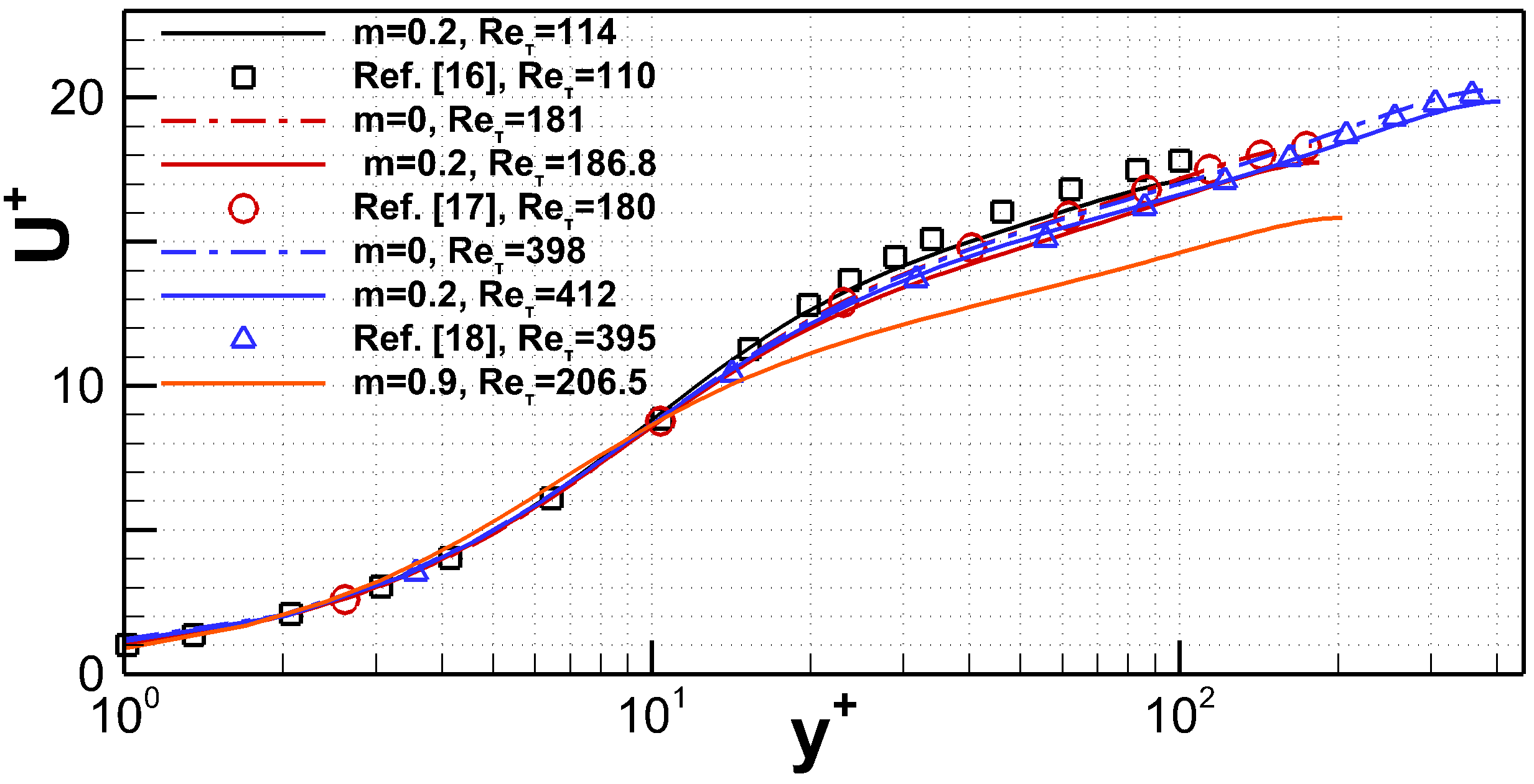
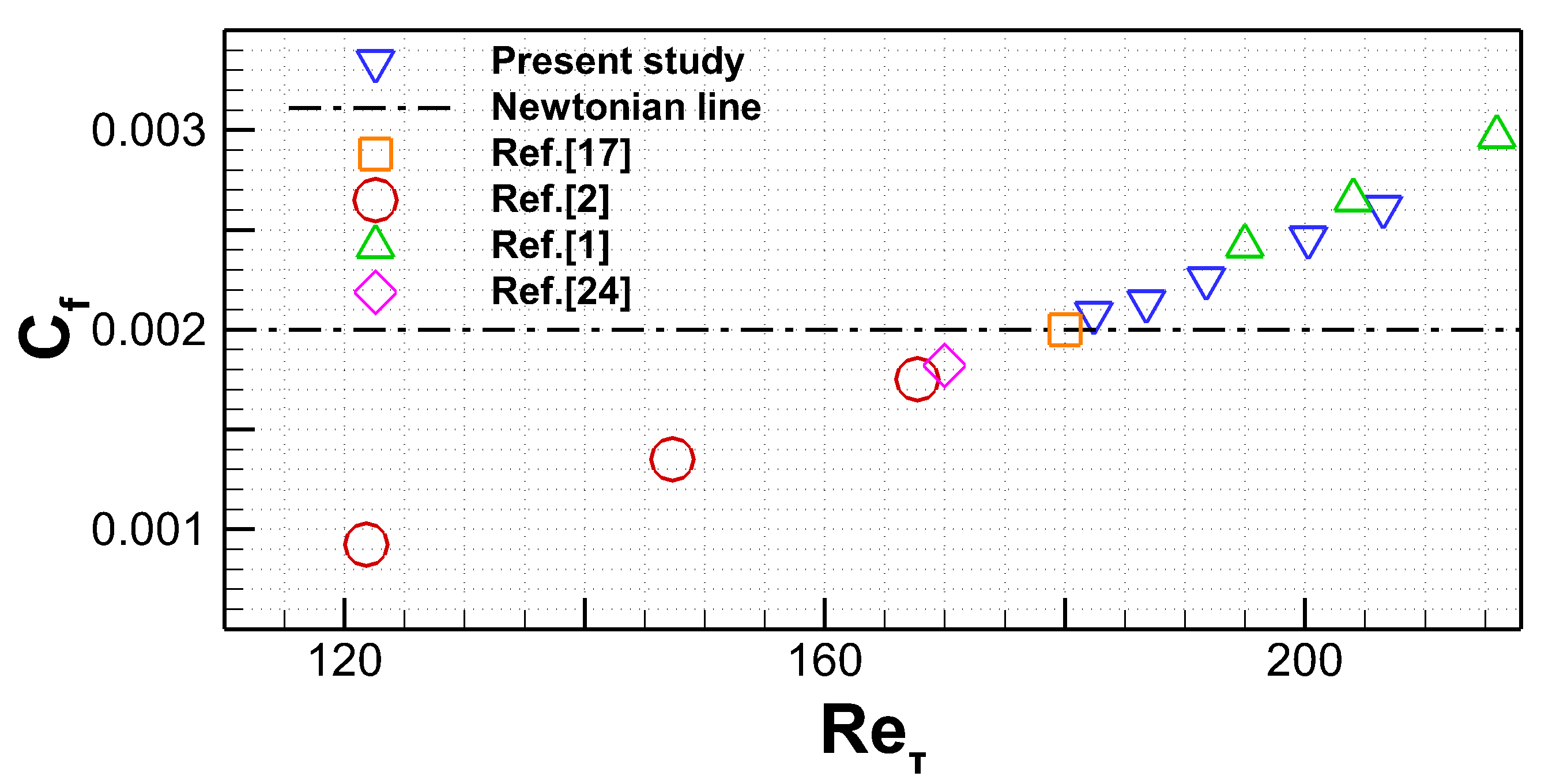
As can be seen in Fig. 1 for example at , the increase of the vortex viscosity parameter from zero in the Newtonian case to cause slope decrease of and consequently, pressure drop increase and turbulence intensification due to the strongly interrotating microstructure. The increase is also connected to the increase of by 8% at most in the case due to increased as the microstructure effect is more significant near the walls, as will be discussed later. The rate of turbulence enhancement as connected by the presence of microstructure can be efficiently presented in the friction factor, , schema of Fig. 2. There, the friction factor variation of various non-Newtonian cases is compared against the present micropolar results as increases. In the case of flows containing polymer additives Dallas:2010 or small heavy solid particles Dritselis:2008 friction is found to decrease in lower values than in the Newtonian one, however, in the case of dense suspensions Picano:2015 as well as in the present case of internal microstructure, friction factor is increased, and thus, turbulence is enhanced with volume fraction and vortex viscosity increase, respectively.
Turbulence enhancement due to microstructure is not only found to exist quantitatively in the above figures, but more importantly qualitatively in the different forms between the flow structures. This is made visual in the streamwise velocity contour snapshots aligned with the and planes of Fig. 3. It is observed that finer structures are encountered for than for in the plane that is a strong indication of shear thickening and the tendency for more isotropic turbulence. Furthermore, the stronger turbulent mixing is evident in the plane, for example at , where finer and isotropic structures are recorded for .
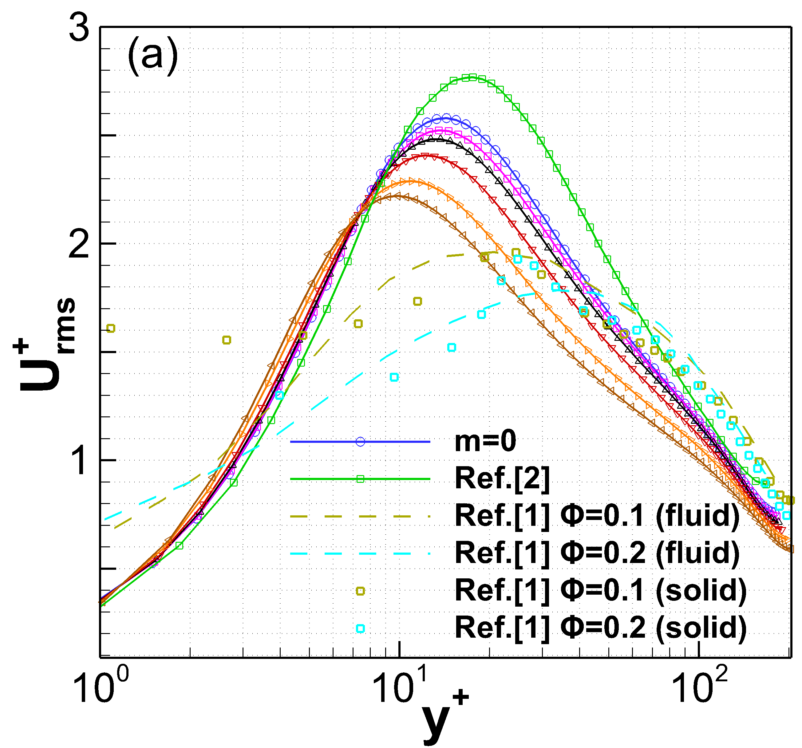
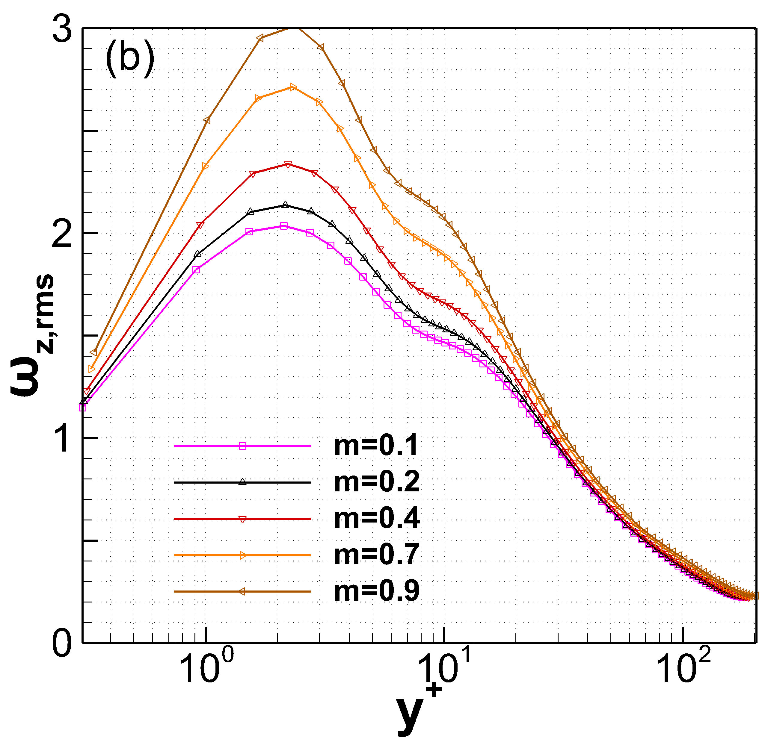
Turbulent statistics, like the velocity root-mean-squared fluctuations that are shown in Fig. 4, also support the turbulence intensification finding due to microstructure. There, some of the present results are compared against polymeric and dense suspension cases at the same Newtonian flow of . As increases, the peak value of the streamwise fluctuation component of the velocity, , is reduced and approaches the wall. Thus, the peak from at goes at about for . Simultaneously, the reduction of peak value indicates the turbulent homogenization trend of internal microstructure due to increasingly turbulent fluctuations of the angular velocity, , as increases, see Fig. 4b. The micropolar fluctuation that mostly interacts with is found to approach its peak value at about for . As compared to the polymer additive case Dallas:2010 , an opposite trend is found due to its shear thinning nature.
Moreover, the present results are in alignment with the dense suspension case of ref. Picano:2015 in two major points, although the visual differences. Firstly, the peak values of are reduced due to shear thickening and this reduction is proportional to particles volume fraction increase, and secondly, despite that the peak value of of the fluid phase at ref. Picano:2015 departs from the walls with volume fraction increase, its particulate counterpart approaches the walls like in the present results. The peak value of the particulate root-mean-squared fluctuation velocity of ref. Picano:2015 is found to be of the same order of magnitude as its fluid part, thus, turbulence intensification is fed by the particulate induced turbulence in dense suspensions.
Similarly here, the internal microstructure is responsible for the turbulence enhancement as can be seen in the stress balance of the micropolar fluids flow equations. In turbulent wall-bounded fluid flows with internal microstructure, the total stress is balanced by Reynolds shear, viscous and microstructure stresses as:
| (3) |
where, and represent the shear and viscous stresses, respectively, while the micropolar stress due to microstructure is , and are the streamwise and wall-normal velocity fluctuations, respectively, and bar indicates temporal and wall-normal plane average.
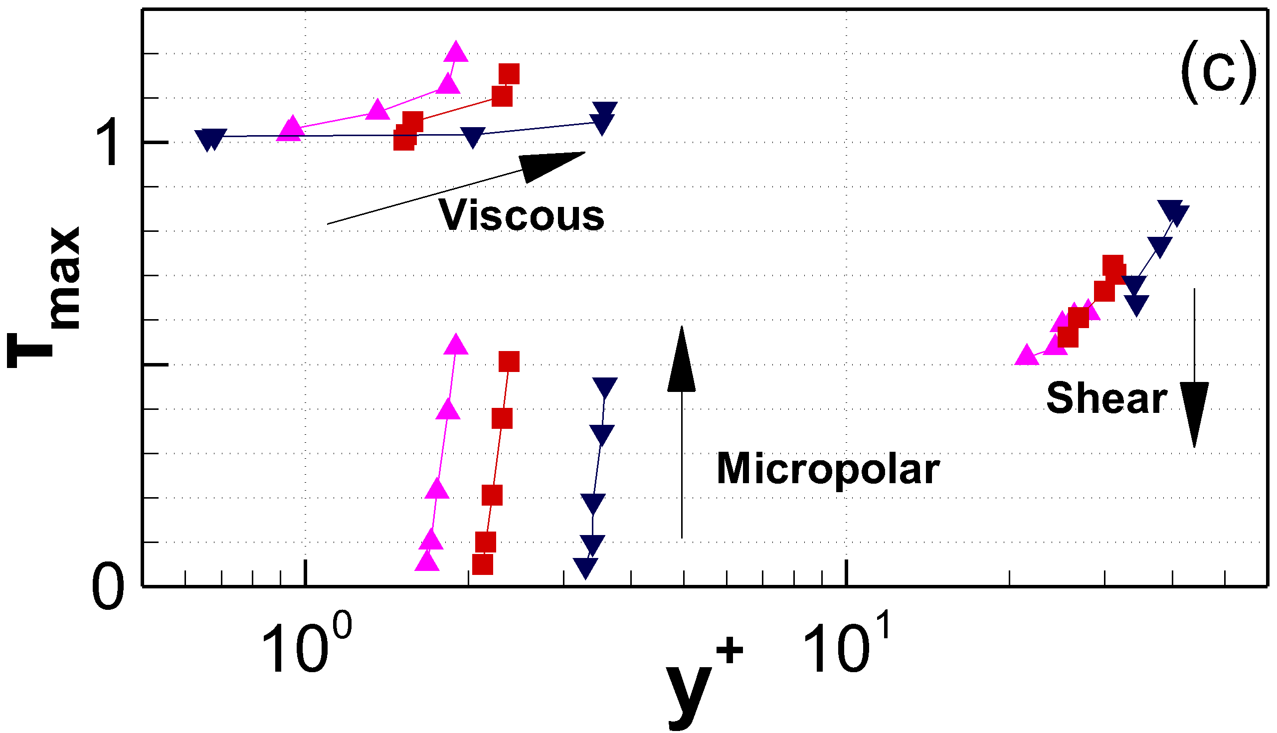
Reynolds stress is the usual mechanism of turbulence production, but here is peculiarly reduced with increase as can be observed in Fig. 5. Similar shear stress decrease is encountered in dense suspensions, polymer flows and flows under the effect of external forces, like external magnetic fields Lee:2001 . Shear reduction is replaced by the simultaneous increase of both, the viscous and micropolar stresses near the walls at . This new turbulence mechanism ignited by the internal microstructure is reported for the first time here. Thus now, the micropolar stress alters the dominance of viscous stress near the walls and, as increases, the magnitude of is getting comparable to that of the viscous one. The micropolar stress is found to be of the same nature as the viscous one, i.e. rises only very close to the wall, while far from it drops to zero and mostly affected by the total viscosity. The peak value of the micropolar stress is found to be located inside the viscous sublayer at for the lower Reynolds number of almost independently of , and with an tendency to departs from the wall as Reynolds number increases. This decrease of shear stress is responsible also for the reduction of total stress, similarly to Lee:2001 , due to the homogenization effect of the internal microstructure.
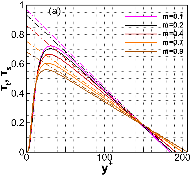
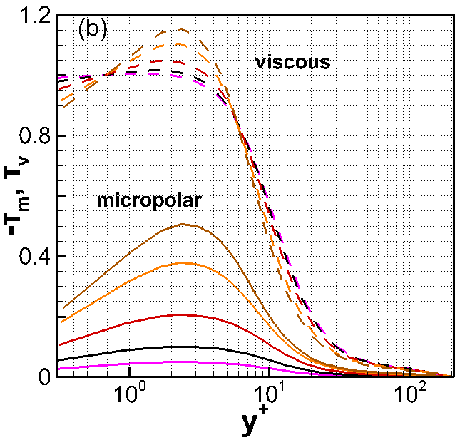
The near walls new induced turbulence mechanism through microstructure is of similar nature as the usual vorticity induced turbulence mechanism of the Newtonian fluids (now act together) that excite streaks structures near the walls Schoppa:2002 . In fact, this is evident from Fig. 5 where the profiles of the mean angular velocity, i.e. , is of similar shape to the fluid spanwise friction vorticity profile, i.e. . It is found easily from the present statistics, and also proved mathematically, that . The difference however of the micropolar stress production is that it is an active term capable to sustain and enhance turbulence, and not a passive one as the usual vorticity is.
In summary, the micropolar set of equations has been applied to investigate the internal microstructure effect in a turbulent fluid flow. Computational experiments have been conducted at relative low Re channel flow and results for different vortex viscosity ratios have been compared against other non-Newtonian fluids flows. Little is known so far for this type of turbulent flows, which ranks this study among pioneer ones. Results exhibit shear thickening, drag increase and enhanced turbulence as the vortex viscosity increases. By further analysis, it has been shown that the main mechanism for turbulence generation in this case is the micropolar stress, as it increases close to the walls when vortex viscosity, and thus microstructure density, increases. The concept of micropolar turbulence formation could lead to a better understanding of turbulence mechanics in more general type of fluids.
The authors are grateful for the support of the Greek Research and Technology Network (GRNET) for the computational time granted in the National HPC facility ARIS.
References
- (1) F. Picano, W.P. Breugem and L. Brandt, J. Fluid Mech. 764, 463–487 (2015).
- (2) V. Dallas, J.C. Vassilicos and G.F. Hewitt, Phys. Rev. E 82, (2010).
- (3) N.J. Wagner and J.F. Brady, Phys. Today 62, 27–32 (2009).
- (4) J.J. Stickel and R.L. Powell, Annu. Rev. Fluid Mech. 37, 129–149 (2005).
- (5) M. Reeks, J. Aerosol Sci. 14, 729–739 (1983).
- (6) F. Picano, W.-P. Breugen, D. Mitra and L. Brandt, Phys. Rev. Lett. 111, 098302 (2013).
- (7) P. Costa, F. Picano, L. Brandt and W.P. Breugem, Phys. Rev. Lett. 117, 134501 (2016).
- (8) B.A. Toms, Proceedings of the International Congress on Rheology 2, 135, North-Holland (1949).
- (9) W.B. Giles and W.T. Pettit, Nature 216, 470–472 (1967).
- (10) W.D. White and D.M. McEligot, J. of Basic Engineering 92(3), 411–418 (1970).
- (11) M.E. Rosti and L. Brandt, Phys. Rev. Fluids 5, 041301 (2020).
- (12) A.C. Eringen, Technical report 27, Purdue University (1965).
- (13) N. Mitarai, H. Hayakawa and H. Nakanishi, Phys. Rev. Lett. 88(17), 174301-1 (2002).
- (14) G. Lukaszewicz, Springer Science and Business Media New York (1999).
- (15) D.W. Condiff and J.S. Dahler, Phys. of fluids 7(6), 842 (1964).
- (16) T. Tsukahara, Y. Seki, H. Kawamura and D. Tochio, 4th International Symposium on Turbulence and Shear Flow Phenomena, Williamsburg, VA, USA, 935-940 (2005).
- (17) J. Kim, P. Moin and R. Moser, J. Fluid Mech. 177, 133–166 (1986).
- (18) R.D. Moser, J. Kim and N.N. Mansour, Phys. of fluids 11, 943 (1999).
- (19) A.C. Eringen, J. Math. Mech. 16, 1-16 (1966).
- (20) M.I. Cheikh, J. Chen and M. Wei, Phys. Rev. Fluids 4, 104610 (2019).
- (21) T. Ariman, M.A. Turk and N.D. Sylvester,J. Appl. Mech. Trans. ASME 41, 1-7 (1974).
- (22) E. Karvelas, G. Sofiadis, T. Papathanasiou and I.E. Sarris, Fluids 5, 125 (2020).
- (23) E.G. Karvelas, A. Tsiantis and T.D. Papathanasiou, Comp. Meth. and Prog. in Biomed.185, 105135 (2020).
- (24) C.D. Dritselis and N.S. Vlachos, Phys. of Fluids 20, 055103 (2008).
- (25) D. Lee and H. Choi, J. Fluid Mech. 439, 367-394 (2001).
- (26) W. Schoppa and F. Hussain, J. Fluid Mech. 453, 57-108 (2002).