Interactive Multiscale Modeling to Bridge Atomic Properties and Electrochemical Performance in Li-CO2 Battery Design
Abstract
Li-CO2 batteries show promise as energy storage solutions, offering high theoretical energy density and CO2 fixation. Their performance relies on the formation and decomposition of Li2CO3/C during discharge and charge cycles, respectively. We used a multiscale modeling framework that integrates Density Functional Theory (DFT), Ab-Initio Molecular Dynamics (AIMD), classical Molecular Dynamics (MD), and Finite Element Analysis (FEA) to investigate atomic and cell-level properties. The Li-CO2 battery consists of a lithium metal anode, an ionic liquid electrolyte, and a carbon cloth porous cathode with a Sb0.67Bi1.33Te3 catalyst. DFT and AIMD determined the electrical conductivities of Sb0.67Bi1.33Te3 and Li2CO3 using the Kubo-Greenwood formalism and studied the CO2 reduction mechanism on the cathode catalyst. MD simulations calculated the CO2 diffusion coefficient, Li+ transference number, ionic conductivity, and Li+ solvation structure. The FEA model, incorporating results from atomistic simulations, reproduced experimental voltage-capacity profiles at 1 mA/cm2 and revealed spatio-temporal variations in Li2CO3/C deposition, porosity, and CO2 concentration dependence on discharge rates in the cathode. Accordingly, Li2CO3 can form toroidal and thin film deposits, leading to dispersed and local porosity changes at 0.1 mA/cm2 and 1 mA/cm2, respectively. The capacity decreases exponentially from 81,570 mAh/g at 0.1 mA/cm2 to 6,200 mAh/g at 1 mA/cm2, due to pore clogging that limits CO2 transport to the cathode interior. Therefore, the performance of Li-CO2 batteries can be significantly improved by enhancing CO2 transport, regulating Li2CO3 deposition, and optimizing cathode architecture.
1 Introduction
Lithium-carbon dioxide (Li-CO2) batteries, with their high theoretical energy density and CO2 fixation capability, have emerged as a potential energy storage solution [1, 2]. These batteries provide a theoretical specific energy density of 1876 Wh kg-1, which is substantially higher than that of current lithium-ion battery systems [3, 4]. This high energy density makes Li-CO2 batteries particularly attractive for applications in aviation, aerospace, and electric vehicles, where lighter and more compact energy storage solutions are crucial [5]. The potential for electric vehicles with much longer ranges or considerably lighter batteries could revolutionize the automotive market [6, 5]. However, Li-CO2 batteries are still in early development stages and face challenges including reaction reversibility issues, low energy efficiency, and the need for improved cathode designs [7]. Ongoing research and development efforts focus on overcoming these limitations, with recent advancements showing promising results [4, 8, 9, 10, 11, 12, 13, 14]. The Li-CO2 batteries operate on a unique electrochemical principle involving the reversible reaction between lithium and carbon dioxide [1, 2] contributing to CO2 capture and utilization efforts [11, 15]. During the discharge process, lithium oxidizes at the anode, releasing lithium ions and electrons . Besides, at the cathode in the presence of solid catalysts [16, 4], CO2 undergoes reduction (), combining with lithium ions and electrons to form primarily lithium carbonate (Li2CO3) and carbon (C) . This discharge reaction typically occurs at a voltage of approximately 2.8 V [17]. The charging process reverses these reactions, decomposing the discharge products to regenerate lithium and CO2. However, due to the stability of Li2CO3, this process requires higher voltages, often exceeding 3.8 V [18]. This voltage requirement highlights one of several key challenges facing Li-CO2 battery technology. The formation of solid Li2CO3 and carbon can lead to electrode clogging and increased internal resistance [9, 19]. The high charging voltages necessary for Li2CO3 decomposition reduce overall energy efficiency [20, 21]. Effective cathode catalysts are critical for enhancing reaction kinetics and minimizing overpotentials in Li-CO2 batteries [8, 22]. Unwanted side reactions, particularly electrolyte decomposition, can occur at high voltages [7]. Furthermore, the inherent inertness of CO2 makes its electrochemical reduction challenging, affecting discharge voltage and efficiency [23, 2, 15].
The Li-CO2 battery chemistry faces critical challenges in catalyst performance, primarily characterized by two fundamental issues, catalyst inefficiency and redox mediator limitations. Noble and transition metal catalysts (such as Pt and Au nanoparticles) demonstrate low catalytic activities for CO2 reduction/evolution reactions in aprotic media, while 2D materials (e.g., MoS2) exhibit poor structural stability at high current rates [18]. Existing catalysts struggle to maintain consistent performance across multiple charge-discharge cycles, often due to catalyst deactivation caused by self-degradation or environmental factors such as discharge product accumulation and species contamination [18]. Unlike Li-O2 batteries, Li-CO2 battery liquid catalysts are typically inactive in decomposing discharge products (Li2CO3 and solid carbon), and current redox mediators fail to effectively facilitate the reversible transformation of reaction intermediates [24]. The formation of Li2CO3, a wide-bandgap insulator, leads to slow kinetics and high voltage platforms (>4.3 V) during the charging process, significantly decreasing the round-trip efficiency of the battery [25]. The lack of efficient decomposition mechanisms significantly impedes battery cycling efficiency, with most current Li-CO2 batteries only capable of operating for dozens of cycles with low overpotential, even with state-of-the-art catalysts [18]. These challenges necessitate developing novel catalytic systems that can maintain high catalytic activity across extended cycling, demonstrate structural stability at elevated current rates, enable efficient decomposition of discharge products, and provide reversible electrochemical reactions with minimal energy loss. The development of catalysts with high catalytic activity and conductivity is crucial to the research of high-performance Li-CO2 batteries [22]. Promising research directions in Li-CO2 battery technology encompass a range of innovative approaches aimed at overcoming current limitations and enhancing overall performance [26, 25, 27]. Advanced solid redox mediators have shown significant potential, as demonstrated by a study using a Cu(II) coordination compound of benzene-1,3,5-tricarboxylic acid. This solid redox mediator enabled a Li-CO2 battery to achieve a higher discharge voltage of 2.8 V, a lower charge potential of 3.7 V, and superior cycling performance over 400 cycles [26]. The use of solid redox mediators addresses the shuttle effect and sluggish kinetics associated with soluble redox mediators, potentially improving long-term stability and efficiency. Alternative reaction pathway engineering has emerged as another promising direction, focusing on promoting the formation of Li2C2O4 instead of Li2CO3 as the discharge product. This approach can reduce the charge potential and improve overall battery performance [25]. For instance, the use of Mo2C as a cathode material has been shown to stabilize Li2C2O4 as the final discharge product, reducing the charge potential to 3.8 V and enhancing the reversibility of the battery [25]. Innovative catalyst designs, including carbon-based and metal-complex catalysts, are being extensively explored. Carbon-based materials, such as multi-walled carbon nanotubes (MWCNTs), are widely used as cathodes due to their high electrical conductivity and large surface area [27]. However, their limited catalytic activity for Li2CO3 decomposition has led to investigations of ways to enhance their performance, such as introducing metal catalysts like Ru to reduce overpotentials and improve efficiency [27]. Transition metal compound catalysts have shown promise in improving the catalytic activity and stability of Li-CO2 batteries. For example, the integration of Ru-catalyzed MWCNT cathodes with solid electrolytes has demonstrated enhanced electrochemical reactions involving CO2 [27]. Additionally, nanostructured catalyst development with improved conductivity and catalytic properties continues to be a focus area, exploring various materials and structures to optimize battery performance [4, 10, 11].
Ionic liquid-based electrolytes show promise for Li-CO2 batteries due to their stability with intermediate products compared to solid-state electrolytes, but their development is limited by low ionic conductivity and high viscosity [18]. To address these limitations, ionic liquid electrolytes based on DMSO (dimethyl sulfoxide) as a solvent and LiTFSI (lithium bis(trifluoromethanesulfonyl)imide) as a salt, often incorporating EMIM-BF4 (1-Ethyl-3-methylimidazolium tetrafluoroborate), have been developed [28, 29, 30, 31, 3, 32, 4]. These electrolytes are preferred for Li-CO2 batteries due to their superior ionic conductivity, enhanced electrochemical stability, and improved CO2 activation properties. DMSO-based electrolytes exhibit faster Li+ ion diffusion kinetics compared to other solvents like TEGDME (tetraethylene glycol dimethyl ether), resulting in lower polarization potential [28]. Li-CO2 batteries using 3M LiTFSI in DMSO electrolyte have demonstrated excellent cycling performance, maintaining stable operation for over 1,900 hours (180 cycles) [28]. In concentrated DMSO-based electrolytes, TFSI- anions can access the primary solvation sheath of Li+ ions, leading to the formation of a LiF-rich solid electrolyte interphase (SEI) layer, which is beneficial for battery performance [29, 30]. DMSO-based electrolytes demonstrate good electrochemical stability with both the Li metal anode and the reactive cathode at high voltages and elevated temperatures [28]. The use of DMSO-based electrolytes improves the rate capability of the battery, with cells able to deliver flat charge/discharge plateaus at current densities of up to 2,000 mA g-1 [29]. Together, these properties make the DMSO LiTFSI electrolyte a promising choice for improving the overall performance and stability of Li-CO2 batteries. The addition of EMIM-BF4 (1-Ethyl-3-methylimidazolium tetrafluoroborate) as an electrolyte material plays several important roles in Li-CO2 batteries. EMIM-BF4 helps in activating CO2 molecules, which is crucial for the CO2 reduction reaction in Li-CO2 batteries [31]. The addition of EMIM-BF4 to the electrolyte has been shown to enhance battery performance. In one study, a Li-CO2 battery using 0.1 M LiTFSI in (EMIM-BF4)/DMSO as the electrolyte achieved 500 cycles at 0.5 A/g with a capacity of 500 mAh/g [28]. The presence of EMIM-BF4 in the electrolyte contributes to improved cycling stability of Li-CO2 batteries [3]. When combined with other electrolyte components like DMSO and LiTFSI, EMIM-BF4 contributes to the overall performance enhancement of Li-CO2 batteries, including higher discharge voltages and increased capacities [32]. Recently, Jaradat et al. used an electrolyte combination of ZnI2, LiTFSI, DMSO, and EMIM-BF4 with a volumetric ratio of 2:3 that led to good Li-CO2 battery performance [4].
Although recent research has focused on novel cathode materials and electrolytes to improve Li-CO2 battery cell performance [10, 33, 34, 11, 14, 13, 35], most computational work has focused primarily on atomistic-level or continuum-level modeling. There is a critical need for a comprehensive multiscale approach that bridges these disparate levels of analysis to provide a more holistic understanding of batteries [36, 37, 38, 39]. To address this gap, we present an interactive multiscale modeling framework for Li-CO2 batteries that integrates density functional theory (DFT), ab initio molecular dynamics (AIMD), classical molecular dynamics (MD), and finite element analysis (FEA) in a coordinated manner. This approach bridges the atomic properties and electrochemical performance of Li-CO2 batteries.
At the Li-CO2 battery cell level, Finite Element Analysis (FEA) effectively simulates charge/discharge cycles, enabling macroscopic analysis of complex processes within the battery cell. These processes include ion transport through porous electrodes, reaction kinetics, and their impact on cell performance [40, 41, 42]. However, FEA requires accurate electrode and electrolyte properties as input parameters, which can be derived from atomistic simulations. At the atomic scale, classical Molecular Dynamics (MD) simulations excel in estimating transport properties such as diffusion coefficients and ionic conductivity in battery electrolytes [43, 44]. Complementing this approach, the combination of Density Functional Theory (DFT) and Ab Initio Molecular Dynamics (AIMD) enables the calculation of electrode electrical conductivity and reaction rate coefficients at the electrolyte/electrode interface [45, 12, 46, 47].
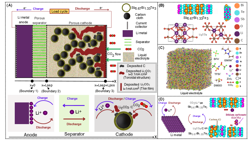
To bridge the gap between atomic and cell-level simulations, we first employ DFT/AIMD calculations to determine the electrical conductivity of Li2CO3 and Sb0.67Bi1.33Te3 using the Kubo-Greenwood formula [48, 49, 50], as well as to study the surface reaction of Li2CO3 as cathode catalyst material. Secondly, we conducted large-scale MD simulations to investigate the transport properties of the liquid electrolyte. Specifically, we calculate the diffusion coefficients of Li+ and CO2, and the Li+ transference number by examining the mean square displacement (MSD) of the particles over time using the Einstein equation [51], and the ionic conductivity using the Green-Kubo formula [52]. Finally, the atomic-scale insights gained from DFT/AIMD and MD simulations are then integrated into our FEA model, allowing for a comprehensive analysis of cell-level performance. Our FEA simulations investigate various aspects of battery cell behavior, including specific capacity, discharge behavior, and voltage-capacity profiles considering factors such as CO2 transport properties, cathode porosity, and deposition of Li2CO3 and carbon. The studied Li-CO2 battery cell consists of a lithium anode, an ionic liquid electrolyte, and a porous cathode. The electrolyte consists of a mixture of 1-ethyl-3-methylimidazolium tetrafluoroborate (EMIM-BF4) and dimethyl sulfoxide (DMSO) in a 2:3 ratio, supplemented with zinc iodide (ZnI2) and 1 M lithium bis(trifluoromethanesulfonyl)imide (LiTFSI) salt. This specific electrolyte composition has been experimentally demonstrated to yield optimal battery cell performance [4]. The cathode uses carbon cloth functionalized with a stable transition metal trichalcogenide alloy catalyst (Sb0.67Bi1.33Te3), improving CO2 reduction and oxidation kinetics [4]. A schematic representation of our multiscale approach is depicted in Figure 1. This multiscale approach enables us to make predictions about porosity, deposited species quantities, and CO2 concentration variations-parameters that are difficult to assess through experimental methods alone. Furthermore, it allows us to evaluate these properties as a function of time, providing dynamic insights into the battery’s behavior. This computational methodology can be used to test and screen various battery materials, potentially saving significant time and resources by reducing the need for extensive experimental tests.
2 Methods and computational details
2.1 Density Function Theory calculations (DFT) for structure optimization
We performed first-principles-based Density Functional Theory (DFT) calculations to optimize the crystal structures of Sb0.67Bi1.33Te3 and Li2CO3 compounds using the Vienna Abinitio Simulation Package (VASP) [53, 54]. The Sb0.67Bi1.33Te3 structure is constructed based on the Sb2Te3 structure from the Materials Project database [55]. Multiple possible structures for Sb0.67Bi1.33Te3 were optimized, and the most energetically favorable configuration (i.e., with the lowest optimization energy) is presented in Figure 1 (B). The Li2CO3 structure presented in 1B is obtained from the Materials Project database [55]. The projector augmented wave (PAW) formalism described the valence electrons of Bi, Sb, Te, Li, C, and O atoms using plane wave-based wave functions was employed [56]. The structure optimization, involving the minimization of ground state energy, utilized the generalized gradient approximation of Perdew and Wang method that brings the correct exchange-correlation part of electronic energy [57, 58]. A kinetic cutoff energy of 500 eV was set to enhance calculation accuracy. The unit cell of both Sb0.67Bi1.33Te3 and Li2CO3 compounds (Figure 1 (B)) extended in all three directions such that the lattice constants become more than 20Å to sample k-meshes of the Brillouin zones, respectively. Ionic and electronic optimizations were alternately performed until the forces on each ion reached less than meV/Å.
For the Sb0.67Bi1.33Te3 surface interaction (Figure 1 (D)), the Perdew-Burke-Ernzerhof (PBE) functional, within the generalized gradient approximation (GGA), was employed to describe the exchange-correlation energy. A plane-wave basis set was used with an appropriate energy cutoff to ensure energy convergence, and the interaction between valence and core electrons was treated using the projector augmented wave (PAW) method. A cut-off energy was set at 500 eV and the Brillouin zone sampled at gamma point with a k-mesh of 4 x 4 x 1. The convergence criterion of the total energy was set to be within 1x10⁻⁵ eV within the K-point integration and optimizations were performed until the forces on each atom were below 0.001 eV/Å. Finally, to account for the van der Waals interactions, the van der Waals D3 corrections were implemented [59]. Zero-point energy, heat capacity, and entropy corrections were computed using statical mechanics within the harmonic approximation.
2.2 Ab initio molecular dynamics (AIMD) and Kubo-Greenwood method for electrical conductivity calculation
Using optimized structures of Sb0.67Bi1.33Te3 and Li2CO3 compounds from our DFT calculation (Figure 1 (B)), we carried out the Ab initio molecular dynamics (AIMD) simulations at 300K up to 1ps with NVT ensemble and 1fs time step to select 10 different frames in the 1ps trajectory data. Subsequently, we generated wavefunctions ( where and are band and k-point indices, respectively) data for the selected frames using DFT calculations as explained by Knyazev et. al. [60, 48] to compute the electronic conductivity based on Kubo-Greenwood (KG) formula. During the calculation of wavefunction data from VASP, we included 100% more unoccupied bands than occupied bands for both Sb0.67Bi1.33Te3 and Li2CO3 compounds to account for excited state wavefunctions and their corresponding energies. The dynamic electrical conductivity is represented as a coefficient of the current density and electric field :
| (1) |
where is the frequency of the external electric field . The important component relates to the energy absorbed by the electrons and is computed by the Kubo-Greenwood formula as [48, 49, 50]
| (2) |
Here, the sum is over all points in the Brillouin zone, band indices and and three spatial dimensions . is the frequency-dependent electrical conductivity. is the elementary charge. is the reduced Planck constant. is the electron mass. is the angular frequency. is the volume of the system. and are the Fermi-Dirac distribution functions for states and . and are the wavefunctions of states and . and i are the energies of states and . is the Dirac delta function. denotes a weight function at a particular point. The wave function is generated from our AIMD simulations at room temperature as explained above. is the Fermi function. In practical calculations, -function is written in terms of the Gaussian function:
| (3) |
where is broadening of the -function. This technical parameter plays an essential role in controlling the algorithm in the Kubo-Greenwood formula, particularly at low frequencies.
2.3 Atomistic Molecular Dynamics simulations (MD)
Classical Molecular Dynamics (MD) simulations were carried out using the Large-scale Atomic/Molecular Massively Parallel Simulator LAMMPS [61]. A cut-off distance of Å is used for both Lennard Jones and Coulomb interactions, and a time-step of fs is utilized. Using a particle-particle particle-mesh solver (PPPM), long-range electrostatic interactions are resolved with an accuracy of 10-4 by mapping atomic charges to a 3D mesh, solving Poisson’s equation on the mesh via 3D Fast Fourier Transforms (FFTs), and interpolating electric fields from mesh points back to atoms. [62, 63]. The electrolyte is prepared using an DMSO:(EMIM+, BF) ratio of 3:2, 1M (Li+, TFSI-), and includes 6000 DMSO molecules, 1857 (EMIM+, BF) pairs , 566 (Li+, TFSI-), 14 ZnI2 and 14 CO2 molecules, giving a total number of atoms of 113142. Each molecule geometry was optimized using the Generalized Amber Force Field (GAFF) [64] and the Universal Force Field force fields (UFF) [65], successively. Then the Automated force field Topology Builder (ATB) is used to obtain the final GROMOS FF parameters for TFSI-, DMSO, EMIM+, BF, and CO2 [66, 67, 68]. We note that the ATB parameter generation considers the following: Lennard-Jones parameters refined against experimental solvation and pure liquid properties, ATB parametrization and validation using a single-range 14 Å cutoff for both Lennard-Jones and Coulomb interactions, atomic charges fitted to quantum mechanical (QM) electrostatic potentials and bonded parameters are assiged using force constants estimated at B3LYP/6-31G* level of theory, resulting in robust symmetry routines for assigning identical parameters to chemically equivalent atoms, bonds, and angles. For a comprehensive understanding of the ATB parameter generation process, refer to the detailed explanations provided in the original research papers [66, 67, 68]. The UFF interaction potential is used for ZnI2. For the Li+, the interaction potential parameters were taken from the Canongia Lopes & Padua (CL&P) force field for ionic liquids [69, 70]. The initial distribution was generated using the Moltemplate package [71]. In this process, the simulated system constituents are placed randomly into an oversized cubic box. Then, the system was energetically minimized to ensure optimal particle distribution. The energy minimization algorithm consists of adjusting particle coordinates iteratively [72]. A finite, unitless stopping tolerance for energy (Estop=10-7) that represents the energy variation between consecutive iterations divided by the energy magnitude, and a stopping tolerance for force (Fstop=10-8 kcal/Å), are chosen. After that, the system is agitated using the Langevin thermostat [73] at T=900 K for t=1 ns, followed by the same process using the Nosé-Hoover thermostat [61, 73]. Then, to reach the desired ambient condition of temperature and pressure (T=300 K, P=1 bar), the simulated systems were equilibrated in the NPT statistical ensemble with isotropic constant pressure control using Berendsen barostat [61, 74]. Firstly, from T=900K to T=300K at a constant pressure of P=500 bar for t=3 ns. Secondly, the pressure decreases from P=500 bar to P=1 bar at a constant temperature of T=300 K over a time period of t=3 ns. In the final NPT equilibration stage, the systems were equilibrated at room temperature and ambient pressure (T=300 K, P=1 bar) for t=10 ns. To investigate the transport properties under conditions similar to experimental settings, we performed simulations in the NVT (constant number of particles, volume, and temperature) statistical ensemble. We employed the Nosé-Hoover thermostat to maintain a constant temperature of 300 K while keeping the volume fixed.
2.4 Finite element model
A mathematical framework has been developed for modeling the behavior of prismatic Li-CO2 batteries, drawing inspiration from previous studies on Li-O2 and Li-ion batteries [75, 76, 77]. The model integrates key principles such as mass and current conservation, species transport phenomena, and reaction kinetics within the cathode and separator regions, with the aim of providing deeper insights into the complex mechanisms that occur within the cell during operation. The Li-CO2 cell under investigation consists of several components: a lithium metal sheet serving as the negative electrode, a separator, a porous carbon cathode coated with Sb0.67Bi1.33Te3, and an organic electrolyte that permeates the porous structures, as illustrated schematically in Figure 1 (A). The used electrolyte composition is described in section 2.3. To facilitate electron transfer, current collectors are located at the rear of both electrodes. This configuration enables a thorough examination of the electrochemical and transport processes that govern battery cell performance and limitations. The main objective of this mathematical framework is to provide a comprehensive understanding of the intricate interactions among various components and processes within the Li-CO2 battery cell system.
2.4.1 Electrode Reactions
Cathode Reaction
The main reaction at the cathode is described by [11]:
| (4) |
where and represent the equilibrium potentials for discharge and charge reactions, respectively [17, 18].
This reaction produces Li2CO3/C as the main products during discharge, which plays a crucial role in the battery’s performance. Li2CO3 and carbon are insoluble in the organic electrolyte and can cover the active surface area inside the porous cathode, block pathways for reactive species (Li+ and CO2), prevent further reactions inside the cathode and thus contribute to the end of cell discharge.
Anode Reaction
2.4.2 Particle transport at the macroscopic level
The Nernst-Planck equation, a continuity equation for the time-dependent concentration of a chemical species, is used to describe the transport of chemical species within the battery cell:
| (6) |
In this context, represents the porosity of the electrode or the electrolyte region in the solution phase, denotes the flux, and indicates the volumetric production rate of species transitioning from the electrode material to the electrolyte within the porous structure. The total flux is composed of three components: diffusion, advection, and electromigration. This implies that the concentration is affected by an ionic concentration gradient , flow velocity v, and an electric field E.
| (7) |
In this equation, denotes the effective diffusion coefficient of the chemical species, represents the valence of the ionic species, represents the elementary charge, represents the Boltzmann constant, and represents the absolute temperature. The electric field may be further decomposed as:
| (8) |
where is the electric potential and is the magnetic vector potential. Therefore, the Nernst–Planck equation is given by:
| (9) |
The primary transport mechanisms in batteries, ionic migration due to electric fields and diffusion due to concentration gradients, are accurately described by the Nernst-Planck equation, which excludes time-varying magnetic effects [78]:
| (10) |
The moving boundaries theory of transference number () gives [79]:
| (11) |
where is the volume occupied by diffusing cations by the boundary in time , the Li+ concentration, F the Faraday constant, and the electric current.
By introducing the electrode surface
| (12) |
Also, we can write as:
| (13) |
with the number of particles and the Avogadro number.
Then:
| (14) |
with, J the molar flux of cations, the current density in the electrolyte, and the Faraday constant.
The primary interest in battery modeling is electrochemical processes rather than fluid dynamics, so the advection term is considered less critical [80]. Furthermore, the porous structure limits large-scale fluid motion, further reducing the importance of advection. By neglecting the Advection term, the Nernst–Planck equation for Li+ and CO2 can be expressed as:
| (15) | |||
| (16) |
The effective diffusion coefficient of a species i (i=Li+, CO2) was calculated using the Bruggeman equation [41, 42]:
| (17) |
The form, in the Bruggeman relation, emerges from the mathematical treatment of a system of spherical particles dispersed in a continuous medium [81]. This form has been found to provide a reasonable empirical fit approximation for many real porous systems, especially at higher porosities [81, 82]. The diffusion coefficient (i=Li+, CO2) is calculated from our MD simulation.
2.4.3 Equations of battery electrochemical properties
The surface density of the liquid phase represents the function of the electrolyte concentration , time , the ionic conductivity , the absolute temperature , the activity coefficient , the universal gas constant , the cathode porosity and electrode solution-phase potential [75, 76].
| (18) |
| (19) |
The solid phase current density is the function of the solid-electrode potential and the electronic conductivity of solid-phase mixture [75, 76],
| (20) |
| (21) |
denotes the starting porosity of the cathode. It is important to mention that the effect of deposits (Li2CO3 and carbon) with low conductivity on was not taken into account, and it was assumed that would not change even as the battery reactions occurred.
Conservation of charge
| (22) |
| (23) |
| (24) |
These equations demonstrate that the transfer current per unit electrode volume corresponds to the electrode chemical reaction rate, where is a symbol representing a species participating in the electrochemical reaction, and are the charge number and the stoichiometric coefficient of species , respectively, is the number of electrons transferred in the reaction, is the specific interfacial area of the pore per unit electrode volume, and is the average transfer current. In the present work, only one electrochemical reaction is considered: the formation of /carbon (/C) inside the porous cathode. In practical cells, battery side reactions can occur during cycling alongside the main electrode reactions. This is reflected by the superficial production rate of a species from the cathode’s solid phase to the pore solution, given by Faraday’s law as a function of the local transfer current density between the cathode/electrolyte interface.
| (25) |
Rate expressions
the Butler-Volmer equation is applied in the model using two rate coefficients because the reactions depends on both concentration of and and concentration of /C:
| (26) |
| (27) |
| (28) |
where is local transfer current density between electrode and
electrolyte interface, is the molar concentration of species at the cathode surface, and are the anodic and cathodic rate constant, respectively, is a symmetry factor equal to 0.5, is surface or activated overpotential for reaction at cathode, and are the voltage drop and the electrical resistivity across /C film formation, respectively, is the volume fraction of solid /C, and is the theoretical open-circuit potential for reaction.
The properties of the /C film, specifically its electrical resistivity , thickness (), and conductivity (), are related by the equations below:
| (29) |
| (30) |
| (31) |
where represents or C, while , , , , and refer to the film thickness of , the change in porosity of the cathode caused by , the molar mass of , the specific area, and the density of , respectively.
The electrochemical reaction at the lithium metal anode, it is given by the general Butler-Volmer equation as follow [75, 76]:
| (32) |
where is exchange current density for anode, is surface or activated overpotential for reaction at anode, and the other parameter are as described above.
The specific area of the electrode/electrolyte interface in Equation 31 is decreased by the morphology and dynamic change in porosity due to /C solid passivation during electrochemical reaction. This effective local surface area per unit volume of electrode can be commonly written by a geometric relation [75, 76]:
| (33) |
where the initial specific surface area, and are the volume fraction of solid /C and initial electrode porosity, respectively.
Transport through /C layer
During discharge, the formed /C creates an additional barrier for Li+ and diffusion from the porous medium to the cathode surface.
This process follows Fick’s law [76], where the flux is proportional to the concentration gradient between the bulk electrolyte and the active surface, sustained by ongoing electrochemical reactions consuming reactants.
| (34) |
where is the effective diffusion coefficient of species across the /C film, and is the thickness of the film. represents the molar concentration of species in the electrolyte, while denotes the molar concentration of species specifically at the cathode surface. The effective diffusivity for both and CO2 reactants is used to describe how the pores are deposited by the /C formation; this can be described by the Bruggeman relation [41, 42]:
| (35) |
The volume fraction of the solid /C and the thickness of the film () can be determined from the cathode volume balance as:
| (36) |
| (37) |
In this context, and represent the molar mass and density of , respectively. The term denotes the volume fraction of the initial solid phase of the cathode material, while indicates the radius of the particles within the electrode.
Initial conditions/Boundary conditions
The governing equations consist of partial differential equations that include time and space as independent variables. The dependent variables were simulated using COMSOL Multiphysics 6 finite element analysis software to examine their spatial and temporal changes. The battery cell was segmented into three regions: the anode, separator, and porous cathode. An extra fine mesh was selected for enhanced accuracy. To reduce computation time, a variable-step solver was employed with a relative tolerance of 1 10-4. This solver decreases the total number of time steps required for calculation. The parameters used in the simulations are presented in Tables S1, S2, and S3. The applied current density, iapp, was considered positive when directed from the cathode to the external circuit (Figure 1 (A)). The total current density passing through boundary 3 was designated as iapp. The Li+ flux at boundaries 1 and 3 (JLi) and CO2 flux at boundary 2 (J) were set to zero. Additionally, the boundary condition ci = 0 was applied to the relevant boundaries (see Table S2). The parameter c was assumed to be equal to the saturation concentration, c, at boundary 3. The boundary conditions are outlined in Table S2. Discharge simulations were conducted with applied current densities (iapp) ranging from 0.1 to 1 mA/cm2, defined as positive in the direction from the cathode to the external circuit.
3 Results and discussion
3.1 Electrical conductivity from DFT, AIMD and Kubo-Greenwood formula
Calculated dynamic electrical conductivities for both Sb0.67Bi1.33Te3 and Li2CO3 are shown in Figure 2, for decremented values of from 0.9 to 0.54 with a step of 0.04. The electrical conductivities calculated for different values of show the conductive behavior of Sb0.67Bi1.33Te3 (a conductivity range of the order of S/m) and insulative behavior of Li2CO3 (a conductivity range of the order of S/m). Quantitatively, the electrical conductivities converge with decreasing , i.e., the dependence of conductivity on is smaller. The static electrical conductivities at zero frequency are calculated by interpolating small frequency data shown in Figure 2 (a2) and (b2). Using values where conductivity is converged, below 0.66 for Sb0.67Bi1.33Te3 and below 0.86 for Li2CO3, our computational analysis reveals a static electrical conductivity of S/m for Sb0.67Bi1.33Te3, indicating its strong electrical conducting properties. This finding aligns with the well-established characteristics of bismuth telluride (Bi2Te3) and its alloys, which are extensively employed in thermoelectric devices due to their good electrical conductivity [83, 84]. The high conductivity can be ascribed to the semiconductor nature of Bi2Te3 and the antimony (Sb) doping effect, which augments the carrier concentration [85]. Experimental investigations on Bi2Te3 have reported electrical conductivity values as high as S/m [84], further corroborating the computational results. Our calculations reveal that lithium carbonate (Li2CO3) exhibits a static electrical conductivity range of S/m, indicating its poor electrical conductivity and insulating behavior [86]. This calculated value aligns closely with experimentally reported values, S/m [87] and S/m [88]. The insulating nature of Li2CO3 can be attributed to its ionic nature and the strong ionic bonds that hinder electron mobility [89].
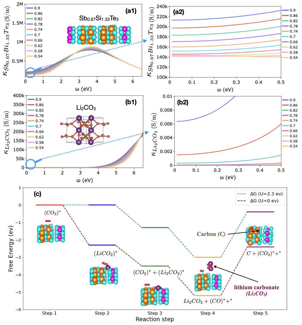
Calculated dynamic electrical conductivities for both Sb0.67Bi1.33Te3 and Li2CO3 are shown in Figure 2 (a1) and (b1) for a large frequency range and in Figures 2 (a2) and (b2) for a small frequency range, for decremented values of from 0.9 to 0.54 with a step of 0.04. Figures 2 (a2) and (b2), the electrical conductivities converge, for small frequencies, with decreasing , i.e., the dependence of conductivity on becomes smaller. The static electrical conductivities at zero frequency are calculated by interpolating small frequency data shown in Figures 2 (a2) and (b2), using values where conductivity has converged, below 0.66 for Sb0.67Bi1.33Te3 and below 0.86 for Li2CO3. The static electrical conductivities calculated for different values of show the conductive behavior of Sb0.67Bi1.33Te3 (a conductivity range on the order of S/m) and insulative behavior of Li2CO3 (a conductivity range on the order of - S/m). Our computational analysis reveals a static electrical conductivity of S/m for Sb0.67Bi1.33Te3, indicating its strong electrical conducting properties. This finding aligns with the well-established characteristics of bismuth telluride (Bi2Te3) and its alloys, which are extensively employed in thermoelectric devices due to their good electrical conductivity [83, 84]. The high conductivity can be attributed to the semiconductor nature of Bi2Te3 and the antimony (Sb) doping effect, which augments the carrier concentration [85]. Experimental investigations on Bi2Te3 have reported electrical conductivity values as high as S/m [84], further corroborating the computational results. Our calculations reveal that lithium carbonate (Li2CO3) exhibits a static electrical conductivity range of S/m, indicating its poor electrical conductivity and insulating behavior [86]. This calculated value aligns closely with experimentally reported values of S/m [87] and S/m [88]. The insulating nature of Li2CO3 can be attributed to its ionic nature and the strong ionic bonds that hinder electron mobility [89]. In Li2CO3, Li+ ions act as the primary charge carriers rather than electrons, a characteristic typical of ionic compounds. The low conductivity of Li2CO3 presents challenges to battery performance, including high internal resistance and passivation of the electrode surface [90, 91]. To address these challenges, potential solutions include enhancing Li2CO3 conductivity, promoting its decomposition through conductive additives or catalysts, designing porous electrodes for increased surface area, and exploring alternative Li2CO3 structures with improved conductivity or decomposition properties.
3.2 Surface reaction of Sb0.67Bi1.33Te3 as cathode catalyst
The DFT calculations of the reaction path for Li2CO3/C formation on the Sb0.67Bi1.33Te3 as Li-CO2 battery cathode catalyst have revealed intriguing insights into the adsorption behavior of reaction products and the step-wise mechanism of the discharge process. To comprehensively understand the formation of Li2CO3/C and C, we calculated the Gibbs free energy (G) changes for various elementary reaction steps on the Sb0.67Bi1.33Te3 catalyst surface, revealing a sequence of intermediate stages that elucidate the complex reaction pathway.
The Gibbs free energy of the reaction was calculated using the following equation:
| (38) |
where ZPE is the zero-point energy, is the heat capacity, is the entropy, is the temperature, and is the electronic energy.
We considered ZPE and entropy changes in Step-1 and assumed that these changes for other elementary steps are small and therefore negligible. The potential-dependent reaction energies were calculated based on the computational hydrogen electrode (CHE) model with reference to the Li/Li+ electrode [92, 93]. The potential-dependent reaction energies profile is shown in Figure 2 (c), and the respective reaction energies of each step are shown in Table 1.
To level up the electrochemical step, a potential was applied to the formation of LiCO2. As can be seen in Figure 2 (c), this potential occurs at 2.3 V versus Li/Li+ electrode.
The reaction begins with the adsorption of CO2∗ on the Bi site, with a Bi-O distance of 3.5 Å. This initial step is marginally endergonic, with a G of 0.002 eV, indicating a slight energy barrier to CO2 adsorption. Following this step, the coupled addition of Li+ and an electron to the adsorbed CO2∗ forms the LiCO2∗ intermediate. This step is highly exergonic, with a G of -2.3 eV, suggesting a thermodynamically favorable process that likely drives the overall reaction forward.
The reaction pathway continues with the interaction between two LiCO2∗ intermediates, producing Li2CO2∗ and CO2∗. This step has a G of -1.2 eV, indicating another energetically favorable process. Subsequently, a pivotal step occurs: the conversion of Li2CO2∗ and CO2∗ into Li2CO3 and CO∗, with a G of 1.7 eV. This step is crucial as it marks the formation of one of the main discharge products, Li2CO3.
The final step in the pathway involves the generation of carbon, facilitated through the reaction of CO∗ and CO2∗. Interestingly, this step is energetically uphill, with a G of 2.8 eV, and also produces CO3∗ on the surface. This energy barrier for carbon formation could explain the observed preferential adsorption of carbon on the catalyst surface, as the system may need to overcome this energy barrier to complete the carbon formation process.
The complete 5-step reaction pathway can be summarized as follows:
| (Step-1) | ||||
| (Step-2) | ||||
| (Step-3) | ||||
| (Step-4) | ||||
| (Step-5) |
These results highlight the essential role of coupled electron-cation transfer processes in the growth of discharge products. The strong exergonic nature of steps 2-4 suggests that these processes occur readily, while the endergonic nature of the final carbon formation step aligns with the observed preferential adsorption of carbon on the Sb0.67Bi1.33Te3 catalyst surface.
The lack of Li2CO3 adsorption on the catalyst surface, as indicated by the simulation, can be explained by the reaction pathway. Li2CO3 is formed in step 4, but this step also releases CO∗ and a free surface site (∗). This suggests that Li2CO3 formation occurs near, but not directly on, the catalyst surface, reducing the cathode porosity and possibly clogging the cathode pores.
These insights into the reaction mechanism have significant implications for catalyst design and overall battery performance. The strong affinity of carbon for the catalyst surface, coupled with the energetically unfavorable step of its formation, suggests that catalyst degradation through carbon accumulation could be a concern over long-term battery operation. This highlights the need for strategies to mitigate carbon build-up, such as developing self-cleaning catalysts or implementing periodic regeneration protocols.
Furthermore, the spatial separation of Li2CO3 formation from the immediate catalyst surface underscores the importance of electrolyte engineering in Li-CO2 battery design. Since Li2CO3 formation appears to occur away from the catalyst, the electrolyte’s ability to facilitate Li2CO3 formation, dissolution, and transport becomes crucial. This suggests that future research should focus on developing electrolytes or additives that can enhance Li2CO3 solubility or promote its formation and decomposition.
| Reaction Step | Reaction Steps | (eV) |
|---|---|---|
| Step-1 | 0.002 | |
| Step-2 | -2.3 | |
| Step-3 | -1.2 | |
| Step-4 | -1.7 | |
| Step-5 | 2.8 |
3.3 Li-CO2 battery electrolyte transport properties and Li+ solvation structure from large scale MD simulation.
This section presents the results of MD simulations that elucidate the atomic-level dynamic and solvation properties of the Li-CO2 battery electrolyte depicted in Figure 3 (a). These simulations provide microscopic insights into the electrolyte’s behavior, bridging the gap between atomic and macroscopic transport properties in our multiscale approach.
3.3.1 Li-CO2 battery electrolyte transport properties
The primary goal is to investigate the electrolyte’s dynamic properties governing ion and CO2 transport mechanisms, including ionic conductivity, cation transference number, and CO2 diffusion coefficient, as presented in Table 2. These properties directly impact the Li-CO2 battery’s electrochemical performance.
The cations transference number is assessed by [94]:
| (39) |
Where the self-diffusion coefficients are determined from the mean-square-displacement of center of mass presented in Figure 3 (b), calculated from the MD simulations as follows [95]:
| (40) |
In the expression above, represents the temporal position of a random walker (ion or CO2 molecule). Here, indicates the time and is an initial time at which the random walker begins to move. The diffusion coefficients are extrapolated from the normal diffusion regime characterized by:
| (41) |
where is crossover time to the normal diffusion regime.
The Green-Kubo (GK) approach [52] that takes the autocorrelation with respect to the ionic current in the electrolyte is used to calculate the ionic conductivity :
| (42) |
with,
| (43) |
Here is the elementary charge, represents the charge number (valence) of ion , is the velocity of ion , is temperature, is the Boltzmann constant, is the volume of the simulation box, and is the number of ions.
| Parameter | Value | Unit | Symbol |
|---|---|---|---|
| Diffusion coefficient of Li+ | 3.17 | 10-9 m2s-1 | D |
| Ionic conductivity | 6.77 (7.4)a | mS cm-1 | |
| Transference number of Li+ | 0.91 (0.88)a | — | |
| Diffusion coefficient of CO2 | 1.2 (1.16)b (1.14)c | 10-9 m2s-1 | D |
The estimated diffusion coefficient of CO2 in DMSO at 25 C is approximately 1.16 10-9 m2/s using the Stokes-Einstein-Gierer-Wirtz (SEGWE) relation and 1.14 10-9 m2/s using the Einstein equation [97]. These values are consistent with our MD calculation result of 1.2 10-9 m2/s presented in Table 2, further validating our findings.
3.3.2 Li+ solvation structure from large scale MD simulation
The structural analysis was conducted utilizing the Radial Distribution Function (RDF), g(r), and Coordination Number (Nc). The RDF quantifies the spatial distribution of particles relative to a reference particle, providing insights into the local structural organization that affect the transport properties in the electrolyte.
The RDF is mathematically expressed as:
| (44) |
with the particle density of type at a distance around particles , and the particle density of type averaged over all spheres around particles with radius . Here, we chose =12Å.
The primary peak in g(r) corresponds to the nearest neighbors, indicating the most probable interparticle distance and interaction strength. This relationship is described by , where and is the interaction potential. Subsequent peaks in the RDF elucidate higher-order neighbor relationships, offering insights into medium-range order, coordination numbers, and packing efficiency. In isotropic, homogeneous systems, g(r) asymptotically approaches unity at large distances, signifying uniform particle distribution.
The coordination number, Nc, is defined as the number of neighboring particles within a specified cutoff distance of the pair interaction potential from a central particle. It is mathematically represented as:
| (45) |
where denotes the distance at which the interparticle interaction potential approaches zero, represents the bulk density, and is the average number density of particles at a given distance r, related to the RDF by = g(r).
The coordination number as a function of distance, N(r), is expressed as:
| (46) |
where r represents an arbitrary distance from a reference particle.
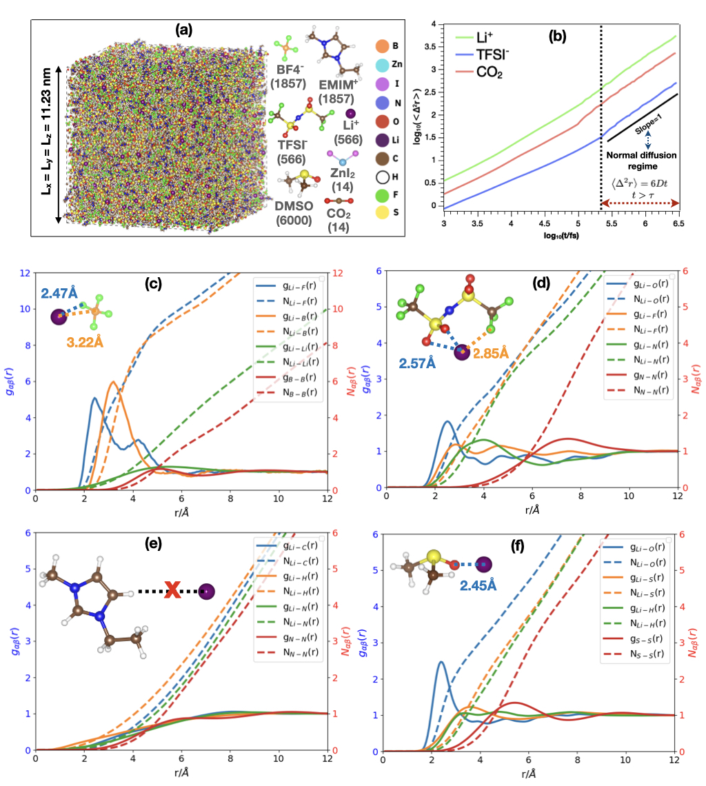
We present the average Radial Distribution Function () and Coordination Number () profiles for BF, TFSI-, and EMIM+ ions, as well as DMSO solvent, surrounding a single Li+ ion. Additionally, we analyze the and between molecules of the same type, represented by their center-of-mass atoms. Li+ ions preferentially coordinate with molecules containing highly electronegative atoms, i.e., atoms with a negative partial charge. The flat curves in Figure 3 (e) indicate a weak interaction between Li+ and EMIM+. Consequently, Li+ primarily coordinates with BF, TFSI-, and DMSO. According to Figure 3 (c), (d), and (f), Li+ ions interact strongly with BF, TFSI-, and DMSO. The most probable distances between Li+ and the constituent atoms are: BF (Li+-F 2.47 Å, Li+-B 3.22 Å), TFSI- (Li+-O 2.57 Å, Li+-F 2.85 Å), and DMSO (Li+-O 2.45 Å). The Li+ cations in the electrolyte are more solvated by BF and DMSO than TFSI-, as evidenced by the higher peaks in the and the corresponding coordination number curves of Li+-BF. BF and DMSO are closer to the Li+ ions than TFSI- ions, playing a crucial role in the dissociation of LiTFSI salt. However, TFSI- can also access the first coordination shell of Li+ due to strong interactions between its O and F atoms and Li+. The presence of both BF and TFSI- facilitates favorable coordination between Li+ and F, potentially leading to the formation of a Li-F solid electrolyte interphase (SEI) that protects the Li-metal anode. Interactions between molecules of the same type are weak due to electrostatic repulsion, resulting in well-dispersed molecules throughout the simulated electrolyte. The average first shell coordination number values for a tagged Li+ cation were determined using a threshold distance of 3 Å, based on the range of the first peaks. Key findings from the coordination number analysis include: Li+-Li+ (, ), Li+-BF (, ), Li+-DMSO (), and Li+-TFSI- (, , ).
The high ionic conductivity and transference number (Table 2) of the simulated electrolyte is derived from several key factors revealed by the solvation structure and interaction analyses (Figure 3). Li+ cations are preferentially solvated by BF and DMSO, promoting LiTFSI salt dissociation and increasing free charge carriers. Weak Li+-TFSI- interactions facilitate easier Li+ transport. The presence of BF and TFSI- creates Li+ conducting channels through favorable Li+-F coordination. Well-dispersed ionic species due to weak same-type molecular interactions enhance efficient ion transport. Optimal coordination numbers (e.g., for BF, for DMSO) allow efficient Li+ transport while maintaining sufficient solvation. Low Li+-Li+ coordination () minimizes clustering, promoting ion mobility. Multiple solvating species create a dynamic environment, facilitating rapid solvating molecule exchange and enhancing Li+ mobility. The preferential solvation of Li+ by BF and DMSO allows for more free movement compared to the larger TFSI- anions, resulting in a higher proportion of the ionic current carried by Li+ and thus increasing the Li+ transference number.
3.4 Cell performance from finite element analysis
The simulated voltage-capacity curves of the Li-CO2 battery cell during the charge-discharge phase is presented in Figure 4 (a). This curve was derived from finite element analysis (FEA) using the atomistic simulation results shown in Figure 2 and Table 2, along with other parameters detailed in Tables S1, S2, and S3. The FEA results were compared with the experimental data obtained from the set-up described in the Supporting Information (SI), at a current density of 1 mA/cm2. The data illustrated in Figure 4 (a) indicate a strong correlation between the simulated results and the experimental voltage. During discharge, the cell potential exhibited a rapid decline from 3.1 V to a plateau of approximately 2.65 V, followed by a gradual reduction to the cutoff voltage of 2.2 V. During charging, the cell potential increased rapidly from 3.7 V to a plateau of 4.2 V, followed by a gradual rise to the cutoff voltage of 4.5 V. Furthermore, the specific capacity, calculated on the basis of the catalyst mass, was about 6200 mAh/g (2.48 mAh/cm2).
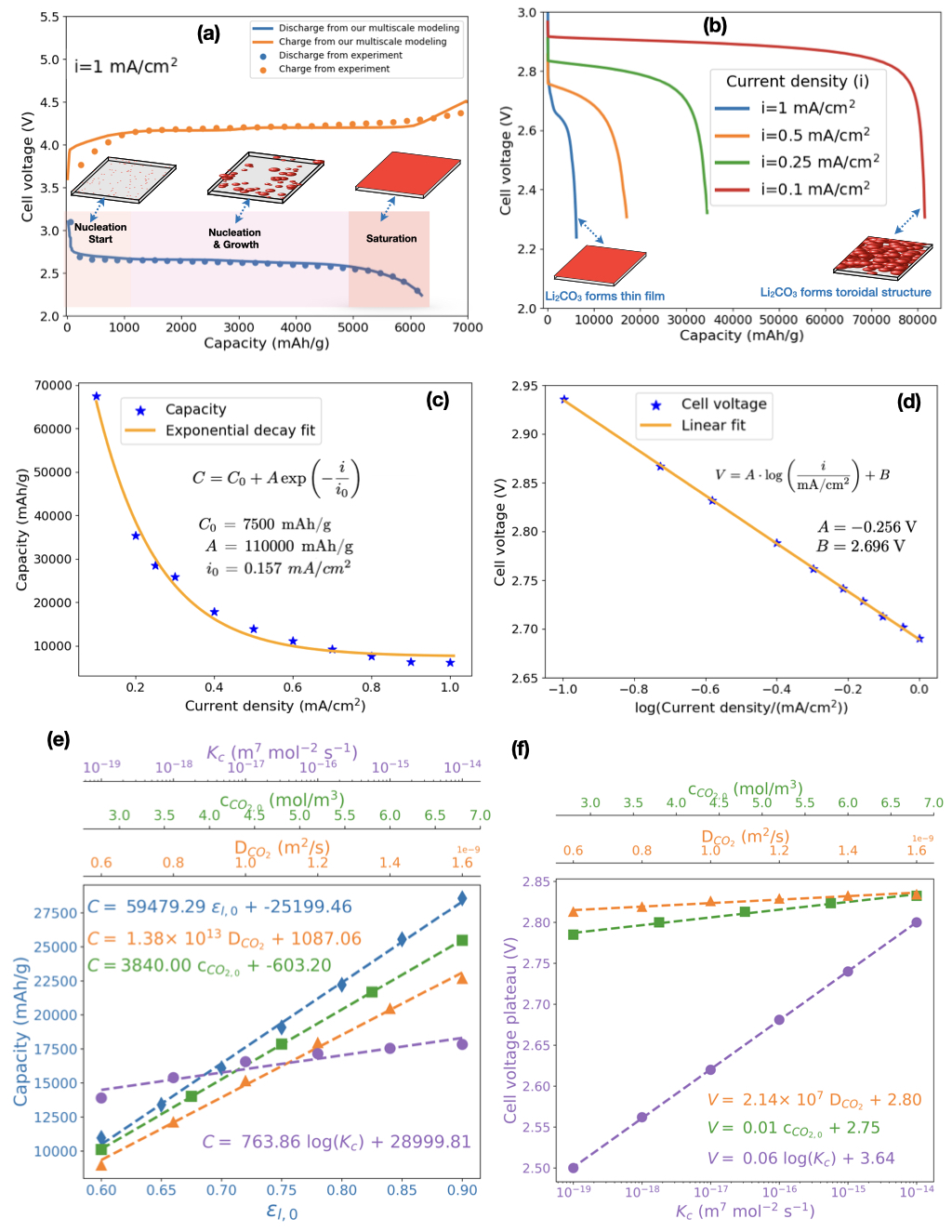
Figure 4 (b) illustrates the impact of applied current density of 1 mA/cm2, 0.5 mA/cm2, 0.25 mA/cm2, and 0.1 mA/cm2 on the simulated discharge curves of Li-CO2 battery cell and Figure S1 (a) shows the same curves for current densities of 0.2 mA/cm2, 0.3 mA/cm2, 0.4 mA/cm2, 0.6 mA/cm2, 0.7 mA/cm2, 0.8 mA/cm2 and 0.9 mA/cm2). The discharge capacity exhibits a substantial reduction, decreasing from 81,570 mAh/g at a low current density of 0.1 mA/cm2 to 6,200 mAh/g at a higher current density of 1 mA/cm2. This observation aligns with prior experimental results, indicating that current density has a significant influence on cell capacity [98]. Furthermore, the discharge voltage plateau decreases as the current density increases (Figure 4 (b)). The capacity decrease at elevated discharge rates can be attributed to limitations in CO2 transport through the cathode, which becomes saturated with electrolyte and unable to sustain the electrochemical reaction. Consequently, as the discharge rate escalates, CO2 reduction is confined to a localized area near the cathode-current collector interface. Furthermore, the rapid reduction in porosity due to Li2CO3 and C deposition on the active area’s surface further impedes CO2 transport into the cell, preventing complete utilization of the electrode’s porosity. Figures 5, S3 and S4 illustrate and analyze these phenomena in detail.
Figure S1 (b) illustrates the overpotential behavior of the studied Li-CO2 battery cell during discharge, revealing a transition from a positive overpotential to a negative overpotential. The initial positive overpotential can be attributed to kinetic and mass transport limitations associated with the CO2 reduction reaction (ORR) at the cathode. This phenomenon is consistent with observations in other battery systems, such as vanadium-manganese flow batteries, where kinetic barriers result in a positive overpotential during discharge [99]. As the discharge progresses, the overpotential becomes negative, indicating a shift in the reaction dynamics. This transition is due to morphological changes in the cathode surface or discharge products (Figure 5 (a1) and (a2)) that could create a more favorable electrochemical environment [22]. Furthermore, as the discharge continues, the distribution of reactants and products becomes more balanced, alleviating initial transport limitations. This phenomenon is related to the morphological changes observed in the cathode surface during discharge (Figure 5 (a1) and (a2)). We note that Li et al. reported that the formation of (lithium oxalate) particles on the cathode surface created a more favorable electrochemical environment by providing additional active sites, improving conductivity and increasing the effective surface area [100]. These changes resulted in higher discharge capacity and improved cycling stability, underscoring the complexity of the discharge process and the importance of optimizing materials and design to enhance overall battery cell performance.
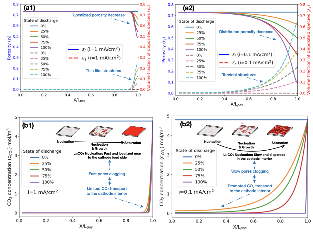
The observed behavior where the overpotential in the Li-CO2 battery cell during discharge decreases to 0 V as current density increases from 0.1 to 1 mA/cm2 can be explained by changes in the morphology and formation mechanism of Li2CO3/C (Figure 5 (a1) and (a2)). It has been found for the Li-air battery that at lower current densities, the deposited species (Li2O2) tends to form larger, toroidal structures, which can lead to higher overpotentials due to less efficient electron transport [101, 102, 103]. Similarly to what was observed for Li-O2 battery, as the current density increases in Li-CO2 battery, the deposited species, Li2CO3 and carbon form a thin film (see Figure 5 (a1) and (a2)), which maintains closer contact with the surface of the conductive catalyst, thus reducing the overpotential (Figure S1 (b)) because Li2CO3 has low electrical conductivity (Figure 2). Figure 4 (c) shows that the capacity of the studied Li-CO2 battery cell decreases exponentially with increasing current density, as can be described by the following equation [102]:
| (47) |
where: = 7500 mAh/g is the baseline capacity, = 110000 mAh/g is a scaling factor, = 0.157 is a characteristic current density. At low current density (i<<0.157 ), the capacity tends towards its maximum value of 117500 mAh/g. This is the sum of the baseline capacity () and the additional capacity represented by . As the current density increases, there is a rapid decrease in the additional capacity provided by , resulting in a decrease in the total capacity . The parameter determines the rate at which the capacity decreases with increasing current density. A smaller would mean a faster decrease in capacity for a given increase in current density, while a larger would indicate a slower decrease. As the current density increases further, the capacity approaches the baseline value of 7500 mAh/g. This suggests that at high current densities, the battery’s capacity is primarily limited to its baseline capacity, as the contribution from the exponential term becomes negligible. The exponential decrease in capacity with increasing current density highlights a trade-off between power output and energy capacity [104]. At higher current densities (i>>0.157 ), the battery can deliver more power, but at the cost of reduced capacity. This is a critical consideration in applications where both high-power and high-capacity are required. The connection between cell voltage () and current density () during the discharge of the studied Li-CO2 battery cell in Figure 4 (d) is represented by the formula [102, 105]:
| (48) |
where V and V. The parameter represents the slope of the voltage change with the logarithm of the current density/(mAcm-2), while represents the voltage at a reference current density of 1 mA/cm2. This formula indicates that as the current density increases, the cell voltage decreases logarithmically, a common characteristic in electrochemical cells due to increased polarization and decreased voltage at higher current densities [102, 105]. The performance of Li-CO2 batteries is governed by a complex interplay of structural and operational parameters, including the initial cathode porosity, CO2 diffusion in the battery electrolyte, initial CO2 concentration in the cathode, and the kinetics of the cathodic reaction. These factors collectively influence key performance metrics, such as capacity and voltage plateau presented in Figure S2 and Figure 4 (e) and (f). Our analysis reveals a strong positive correlation between porosity () and capacity (), as demonstrated by the best linear fit equation:
| (49) |
This trend is attributed to the increased surface area and improved CO2 accessibility in higher porosity structures, which facilitate more efficient electrochemical reactions. Similarly, the CO2 diffusion coefficient () and initial CO2 concentration () exhibit significant positive correlations with capacity, as shown by the best linear fit equations:
| (50) |
| (51) |
These results highlight the critical role of CO2 transport and availability in determining battery capacity. Enhanced diffusion and higher CO2 concentrations improve the accessibility of CO2 to active sites, thereby promoting more efficient electrochemical reactions. This is consistent with recent findings by Chen et al., who demonstrated that a Li-O2/CO2 battery can achieve a full discharge capacity of 6628 mAh/g and a long life of 715 cycles, surpassing the performance of pure Li-O2 batteries [106]. However, the cathodic reaction rate constant () shows a logarithmic relationship with both capacity and voltage plateau, as evidenced by:
| (52) |
| (53) |
This logarithmic relationship underscores the significant impact of reaction kinetics on battery performance, emphasizing the need for efficient catalysts to optimize reaction rates. Furthermore, both CO2 diffusion and concentration demonstrate positive correlations with the voltage plateau, as shown by:
| (54) |
| (55) |
These findings indicate that improving CO2 transport and availability not only enhances capacity but also stabilizes the voltage plateau, which is critical for achieving stable and efficient battery operation. A recent study demonstrated a high-performance Li-CO2 battery using a Cu(II) solid redox mediator, achieving a higher discharge voltage of 2.8 V and a lower charge potential of 3.7 V [25]. Therefore, optimizing the cathode porosity, CO2 diffusion and concentration, while improving reaction kinetics through advanced catalysts, are essential strategies for enhancing the performance of Li-CO2 batteries. Future research should focus on developing innovative electrode materials, electrolyte and catalytic systems to leverage these relationships and advance the practical application of Li-CO2 batteries as a sustainable energy storage technology. For instance, a recent study reported a high-rate Li-CO2 battery enabled by a 2D medium-entropy catalyst, which operates at a high current density of 5000 mA/g and capacity of 5000 mAh/g for up to 125 cycles, far exceeding previously reported values [32]. Figure 5 (a1) and (a2) illustrate how porosity () and volume fraction of Li2CO3/C deposited species () change over space and time with current densities of i=1 mA/cm2 and i=0.1 mA/cm2, respectively. Figure S3 presents a comparison of these parameters at i=0.1, i=0.25, i=0.5, and i=1 mA/cm2. For high current density (i=1 mA/cm2), porosity decreases gradually, primarily near the CO2 feed side of the cathode (X/L=1), from its initial value of to 0.48 at the end of discharge. This decrease is due to the formation of a thin film of Li2CO3/C, represented by the gradual increase of from 0 to 0.25 near the cathode feed side. This film formation leads to electrode clogging, impeding efficient CO2 diffusion into the cathode. For low current density (i=0.1 mA/cm2), Li2CO3/C forms larger toroidal structures [101, 102, 103], evidenced by the gradual increase of across a wider region of the cathode from 0 to 0.64. This results in a distributed porosity decrease from 0.73 to 0.09, initially allowing more CO2 transport into the cathode. However, as discharge progresses, the substantial porosity decrease hinders CO2 diffusion even at low current densities. Figure 5 (b1) and (b2) present the CO2 concentration profiles within the cell during discharge at i=1 mA/cm2 and i=0.1 mA/cm2, respectively. Figure S4 compares concentration profiles at various current densities. At i=1 mA/cm2, the CO2 concentration () decreases sharply from its initial value of 4.8 mol/m3 to 0 mol/m3 in the porous cathode, indicating strongly impeded CO2 diffusion. At i=0.1 mA/cm2, the decrease is more gradual. The impediment to CO2 transport, which is inversely proportional to the current density, results from the accumulation of Li2CO3 and carbon on the active cathode surface. This accumulation reduces pore availability for the electrolyte, increases the amount of insulating species, and obstructs pores, collectively restricting CO2 transport and limiting cell capacity (Figure 4 (c)). To address these limitations, an ideal cathode should feature: large surface area for reaction sites and product deposition, large pores to facilitate active species transport and prevent clogging, high porosity to accommodate discharge product growth, and high electrical conductivity and stability. Such a cathode design could mitigate the observed limitations and potentially enhance the overall performance of Li-CO2 batteries [107].
4 Conclusion
Our interactive multiscale modeling framework, integrating FEA, MD, and DFT/AIMD, provides comprehensive insights into Li-CO2 battery electrochemistry. This approach accurately predicts cell performance while considering critical factors such as CO2 transport, cathode porosity, and Li2CO3/C deposition.
DFT/AIMD calculations reveal high electrical conductivity in the cathode catalyst, while MD simulations show favorable electrolyte properties. FEA results demonstrate an exponential decrease in discharge capacity with increasing current density, from 81,570 mAh/g at 0.1 mA/cm2 to 6,200 mAh/g at 1 mA/cm2, primarily due to CO2 transport limitations and reduced cathode porosity. Li2CO3/C deposit morphology transitions from larger toroidal structures at lower current densities to thin films at higher current densities, significantly impacting performance. The evolution of the overpotential during discharge reflects changing reaction dynamics, while CO2 concentration variation plays a crucial role in determining battery performance.
Our multiscale approach bridges atomic-level phenomena and cell-level performance, offering unique insights into spatiotemporal evolution of critical battery parameters and reducing the need for extensive prototyping. Future research should focus on enhancing CO2 transport, mitigating deposit formation, and optimizing cathode designs with large surface areas, optimal pore sizes, and high porosity. This framework accelerates the development of high-performance Li-CO2 batteries and sustainable energy storage technologies by providing insights into phenomena difficult to observe experimentally in real-time.
CRediT Authorship Contribution Statement
Mohammed Lemaalem, Selva C. Selvaraj, and Naveen K. Dandu: Conceptualization, Visualization, Software, Data Curation, Formal Analysis, Methodology, Writing – Original Draft, Writing – Review & Editing. Ilias Papailias and Arash Namaeighasemi: Methodology, Data Curation, Formal Analysis, Writing – Review & Editing. Larry A. Curtiss and Amin Salehi-Khojin: Supervision, Data Curation, Formal Analysis, Writing – Review & Editing. Anh T. Ngo: Supervision, Conceptualization, Data Curation, Formal Analysis, Investigation, Project Administration, Writing – Review & Editing.
Author Contributions
This work was conceived by A. T. N.. M. L., S. C. S., and N. K. D., carried out the calculations, including first-principles DFT, AIMD results, large-scale MD simulations, and Finite element analysis. I. P., A. N., L. A. C., and A. S. K. were responsible for the experimental measurements. All authors contributed to the discussion of the results and the final manuscript.
Declaration of Competing Interest
The authors declare that they have no known competing financial interests or personal relationships that could have appeared to influence the work reported in this paper.
Acknowledgements
This work was supported by the Assistant Secretary for Energy Efficiency and Renewable Energy, Office of Vehicle Technologies of the US Department of Energy, through the Battery Materials Research (BMR) program. We gratefully acknowledge the computing resources provided on Bebop, a high-performance computing cluster operated by the Laboratory Computing Resource Center (LCRC) at Argonne National Laboratory.
Appendix A. Supplementary material
Description of the experimental setup; a table of parameters used in the finite element analysis (FEA); a table of boundary conditions used in FEA; a table of initial values for independent and dependent variables used in FEA; plots showing the variation of positive electrode over-potential during the discharge process at various current densities as a function of the state of discharge; and plots illustrating changes in porosity and volume fraction of deposited species in the cathode throughout the discharge process at different current densities and discharge states.
Data availability
The data that support the plots within this paper and other findings of this study are available from the corresponding author upon reasonable request.
References
- [1] H. Lv, X. L. Huang, X. Zhu, B. Wang, Metal-related electrocatalysts for Li-CO batteries: an overview of the fundamentals to explore future-oriented strategies, Journal of Materials Chemistry A 10 (48) (2022) 25406–25430.
- [2] Y. Qiao, J. Yi, S. Wu, Y. Liu, S. Yang, P. He, H. Zhou, Li-CO electrochemistry: a new strategy for CO fixation and energy storage, Joule 1 (2) (2017) 359–370.
- [3] A. Ahmadiparidari, R. E. Warburton, L. Majidi, M. Asadi, A. Chamaani, J. R. Jokisaari, S. Rastegar, Z. Hemmat, B. Sayahpour, R. S. Assary, et al., A long-cycle-life lithium-CO battery with carbon neutrality, Advanced Materials 31 (40) (2019) 1902518.
- [4] A. Jaradat, M. K. Ncube, I. Papailias, N. Rai, K. Kumar, V. Koverga, R. Y. Nemade, C. Zhang, N. Shan, H. Shahbazi, et al., Fast charge-transfer rates in Li-CO batteries with a coupled cation-electron transfer process, Advanced Energy Materials 14 (15) (2024) 2303467.
- [5] A. D. Pathak, P. R. Adhikari, W. Choi, Lithium-CO batteries and beyond, Frontiers in Energy Research 11 (2023) 1150737.
- [6] Z. P. Cano, D. Banham, S. Ye, A. Hintennach, J. Lu, M. Fowler, Z. Chen, Batteries and fuel cells for emerging electric vehicle markets, Nature energy 3 (4) (2018) 279–289.
- [7] E. R. Ezeigwe, L. Dong, R. Manjunatha, Y. Zuo, S.-Q. Deng, M. Tan, W. Yan, J. Zhang, D. P. Wilkinson, A review of lithium-O/CO and lithium-CO batteries: Advanced electrodes/materials/electrolytes and functional mechanisms, Nano Energy 95 (2022) 106964.
- [8] Q. Pan, X. Ma, H. Wang, Y. Shu, H. Liu, L. Yang, W. Li, J. Liu, Y. Wu, Y. Mao, et al., Approaching splendid catalysts for Li-CO battery from the theory to practical designing: A review, Advanced Materials 36 (38) (2024) 2406905.
- [9] Z. Zhang, X. Xiao, A. Yan, Z. Zhang, P. Tan, Unravelling the capacity degradation mechanism of thick electrodes in lithium-carbon dioxide batteries via visualization and quantitative techniques, Advanced Functional Materials (2024) 2407422.
- [10] T. Yao, Z. Xu, T. Hu, K. Hu, X. Cui, L. Shen, High-throughput computation and machine learning prediction accelerating the design of cathode catalysts for Li-CO batteries, The Journal of Physical Chemistry C 128 (28) (2024) 11534–11542.
- [11] X. Mu, P. He, H. Zhou, Toward practical Li-CO batteries: Mechanisms, catalysts, and perspectives, Accounts of Materials Research (2024).
- [12] Y. Liu, Z. Zhang, J. Tan, B. Chen, B. Lu, R. Mao, B. Liu, D. Wang, G. Zhou, H.-M. Cheng, Deciphering the contributing motifs of reconstructed cobalt (II) sulfides catalysts in Li-CO batteries, Nature Communications 15 (1) (2024) 2167.
- [13] Y. Xiao, S. Hu, Y. Miao, F. Gong, J. Chen, M. Wu, W. Liu, S. Chen, Recent progress in hot spot regulated strategies for catalysts applied in Li-CO batteries, Small 20 (1) (2024) 2305009.
- [14] S. Sandhiya, P. Elumalai, Compositionally engineered NiCoLDH@ rGO as bifunctional cathode catalyst for rechargeable Li-O/Li-CO battery, Electrochimica Acta 487 (2024) 144195.
- [15] F. S. Gittleson, W.-H. Ryu, A. D. Taylor, Operando observation of the gold-electrolyte interface in Li-O batteries, ACS Applied Materials & Interfaces 6 (21) (2014) 19017–19025.
- [16] X. Sun, X. Mu, W. Zheng, L. Wang, S. Yang, C. Sheng, H. Pan, W. Li, C.-H. Li, P. He, et al., Binuclear Cu complex catalysis enabling Li-CO battery with a high discharge voltage above 3.0 v, Nature Communications 14 (1) (2023) 536.
- [17] M. Wang, K. Yang, Y. Ji, X. Liao, G. Zhang, M. G. Masteghin, N. Peng, F. Richheimer, H. Li, J. Wang, et al., Developing highly reversible Li-CO batteries: from on-chip exploration to practical application, Energy & environmental science 16 (9) (2023) 3960–3967.
- [18] S. Zhang, L. Sun, Q. Fan, F. Zhang, Z. Wang, J. Zou, S. Zhao, J. Mao, Z. Guo, Challenges and prospects of lithium-CO batteries, Nano Research Energy 1 (1) (2022).
- [19] M. Sarkar, R. Hossain, J. Peng, N. Sharma, V. Sahajwalla, Electrochemical compatibility of microzonal carbon in ion uptake and molecular insights into interphase evolution for next-generation Li-Ion batteries, Advanced Energy Materials (2024) 2401977.
- [20] L. Ma, A. Wang, S. Zhang, P. Zhang, J. Wang, Unraveling the decomposition mechanism of LiCO in the aprotic medium by isotope-labeled differential electrochemical mass spectrometry, Journal of Energy Chemistry 73 (10) (2022) 1.
- [21] L. Zhou, H. Wang, K. Zhang, Y. Qi, C. Shen, T. Jin, K. Xie, Fast decomposition of LiCO/C actuated by single-atom catalysts for Li-CO batteries, Sci. China Mater 64 (9) (2021) 2139–2147.
- [22] Y. Jiao, J. Qin, H. M. K. Sari, D. Li, X. Li, X. Sun, Recent progress and prospects of Li-CO batteries: Mechanisms, catalysts and electrolytes, Energy Storage Materials 34 (2021) 148–170.
- [23] X. Yu, A. Manthiram, Recent advances in lithium-carbon dioxide batteries, Small Structures 1 (2) (2020) 2000027.
- [24] Y. Dou, Z. Xie, Y. Wei, Z. Peng, Z. Zhou, Redox mediators for high-performance lithium-oxygen batteries, National Science Review 9 (4) (2022) nwac040.
- [25] W. Li, M. Zhang, X. Sun, C. Sheng, X. Mu, L. Wang, P. He, H. Zhou, Boosting a practical Li-CO battery through dimerization reaction based on solid redox mediator, Nature Communications 15 (1) (2024) 803.
- [26] J. Wang, S. Tian, Y. Lin, H. Song, N. Feng, G. Yang, Q. Zhao, Recent advancement in designing catalysts for rechargeable Li-CO batteries, Catalysis Science & Technology (2024).
- [27] D. Na, D. Yu, H. Kim, B. Yoon, D. D. Lee, I. Seo, Enhancing the performance and stability of Li-CO batteries through LAGTP solid electrolyte and MWCNT/Ru cathode integration, Nanomaterials 14 (23) (2024) 1894.
- [28] Z. Lu, M. Xiao, S. Wang, D. Han, Z. Huang, S. Huang, Y. Meng, A rechargeable Li-CO battery based on the preservation of dimethyl sulfoxide, Journal of Materials Chemistry A 10 (26) (2022) 13821–13828.
- [29] W. Zhang, F. Zhang, S. Liu, W. K. Pang, Z. Lin, Z. Guo, L. Chai, Regulating the reduction reaction pathways via manipulating the solvation shell and donor number of the solvent in Li-CO chemistry, Proceedings of the National Academy of Sciences 120 (14) (2023) e2219692120.
- [30] R. Pipes, A. Bhargav, A. Manthiram, Phenyl disulfide additive for solution-mediated carbon dioxide utilization in Li-CO batteries, Advanced Energy Materials 9 (21) (2019) 1900453.
- [31] Y. Wu, S. Cao, J. Hou, Z. Li, B. Zhang, P. Zhai, Y. Zhang, L. Sun, Rational design of nanocatalysts with nonmetal species modification for electrochemical CO reduction, Advanced Energy Materials 10 (29) (2020) 2000588.
- [32] A. Jaradat, C. Zhang, S. Shashikant Sutar, N. Shan, S. Wang, S. K. Singh, T. Yang, K. Kumar, K. Sharma, S. Namvar, et al., A high-rate Li-CO battery enabled by 2D medium-entropy catalyst, Advanced Functional Materials 33 (21) (2023) 2300814.
- [33] Y. Shi, B. Wei, D. Legut, S. Du, J. S. Francisco, R. Zhang, Highly stable single-atom modified mxenes as cathode-active bifunctional catalysts in Li-CO battery, Advanced Functional Materials 32 (48) (2022) 2210218.
- [34] C. Guo, F. Zhang, X. Han, L. Zhang, Q. Hou, L. Gong, J. Wang, Z. Xia, J. Hao, K. Xie, Intrinsic descriptor guided noble metal cathode design for Li-CO battery, Advanced Materials 35 (33) (2023) 2302325.
- [35] X. Xiao, W. Yu, W. Shang, P. Tan, Y. Dai, C. Cheng, M. Ni, Investigation on the strategies for discharge capacity improvement of aprotic Li-CO batteries, Energy & Fuels 34 (12) (2020) 16870–16878.
- [36] W. Yu, N. Deng, Y. Feng, X. Feng, H. Xiang, L. Gao, B. Cheng, W. Kang, K. Zhang, Understanding multi-scale ion-transport in solid-state lithium batteries, eScience (2024) 100278.
- [37] S. Rizvi, M. W. Tahir, N. Ramzan, C. Merten, Multiscale-multidomain model order reduction of Lithium-ion batteries for automobile application: A review, Journal of Energy Storage 99 (2024) 113390.
- [38] K. Yang, L. Zhang, W. Wang, C. Long, S. Yang, T. Zhu, X. Liu, Multiscale modeling for enhanced battery health analysis: Pathways to longevity, Carbon Neutralization (2024).
- [39] G. Li, C. W. Monroe, Multiscale lithium-battery modeling from materials to cells, Annual review of chemical and biomolecular engineering 11 (1) (2020) 277–310.
- [40] J. Bao, W. Xu, P. Bhattacharya, M. Stewart, J.-G. Zhang, W. Pan, Discharge performance of Li-O batteries using a multiscale modeling approach, The Journal of Physical Chemistry C 119 (27) (2015) 14851–14860.
- [41] M. R. Mehta, K. B. Knudsen, W. R. Bennett, B. D. McCloskey, J. W. Lawson, Li-O batteries for high specific power applications: a multiphysics simulation study for a single discharge, Journal of Power Sources 484 (2021) 229261.
- [42] Y. Mukouyama, S. Hanada, T. Goto, S. Nakanishi, Finite element modeling of the cycle characteristics of Li-O secondary batteries considering surface-and solution-route discharge reactions, The Journal of Physical Chemistry C 127 (22) (2023) 10459–10469.
- [43] G.-X. Li, V. Koverga, A. Nguyen, R. Kou, M. Ncube, H. Jiang, K. Wang, M. Liao, H. Guo, J. Chen, et al., Enhancing lithium-metal battery longevity through minimized coordinating diluent, Nature Energy (2024) 1–11.
- [44] M. Lemaalem, P. Carbonnière, Tunable properties of poly (vinylidene fluoride)-derived polymers for advancing battery performance and enabling diverse applications, Polymer 283 (2023) 126218.
- [45] Q. Deng, Y. Yang, W. Zhao, Z. Tang, K. Yin, Y. Song, Y. Zhang, Revealing the construction of cuoce interfacial sites via increased support utilization for enhanced CO electroreduction and Li-CO batteries, Journal of Colloid and Interface Science 651 (2023) 883–893.
- [46] R. Car, M. Parrinello, Unified approach for molecular dynamics and density-functional theory, Physical review letters 55 (22) (1985) 2471.
- [47] D. Marx, J. Hutter, Ab initio molecular dynamics: basic theory and advanced methods, Cambridge University Press, 2009.
- [48] D. Knyazev, P. Levashov, Ab initio calculation of transport and optical properties of aluminum: Influence of simulation parameters, Computational materials science 79 (2013) 817–829.
- [49] R. Kubo, J. phys. soc. jpn., J. Phys. Soc. Jpn 12 (570) (1957).
- [50] D. Greenwood, Proc. phys. soc., London 71 (1958) 585.
- [51] M. Lemaalem, P. Carbonniere, Effects of solvents on Li distribution and dynamics in PVDF/LiFSI solid polymer electrolytes: An all-atom molecular dynamics simulation study, Solid State Ionics 399 (2023) 116304.
- [52] S. Tovey, F. Zills, F. Torres-Herrador, C. Lohrmann, M. Brückner, C. Holm, Mdsuite: comprehensive post-processing tool for particle simulations, Journal of Cheminformatics 15 (1) (2023) 19.
- [53] G. Kresse, J. Hafner, Ab initio molecular dynamics for liquid metals, Physical review B 47 (1) (1993) 558.
- [54] G. Kresse, J. Hafner, Ab initio molecular-dynamics simulation of the liquid-metal-amorphous-semiconductor transition in germanium, Physical Review B 49 (20) (1994) 14251.
- [55] A. Jain, S. P. Ong, G. Hautier, W. Chen, W. D. Richards, S. Dacek, S. Cholia, D. Gunter, D. Skinner, G. Ceder, et al., Commentary: The materials project: A materials genome approach to accelerating materials innovation, APL materials 1 (1) (2013).
- [56] P. E. Blöchl, Projector augmented-wave method, Physical review B 50 (24) (1994) 17953.
- [57] J. P. Perdew, K. Burke, M. Ernzerhof, Generalized gradient approximation made simple, Physical review letters 77 (18) (1996) 3865.
- [58] K. Burke, J. P. Perdew, Y. Wang, Derivation of a generalized gradient approximation: The PW91 density functional, in: Electronic Density Functional Theory: recent progress and new directions, Springer, 1998, pp. 81–111.
- [59] S. Grimme, J. Antony, S. Ehrlich, H. Krieg, A consistent and accurate ab initio parametrization of density functional dispersion correction (dft-d) for the 94 elements h-pu, The Journal of chemical physics 132 (15) (2010).
- [60] D. Knyazev, P. R. Levashov, Thermodynamic, transport, and optical properties of dense silver plasma calculated using the GreeKuP code (2019).
- [61] A. P. Thompson, H. M. Aktulga, R. Berger, D. S. Bolintineanu, W. M. Brown, P. S. Crozier, P. J. in’t Veld, A. Kohlmeyer, S. G. Moore, T. D. Nguyen, et al., Lammps-a flexible simulation tool for particle-based materials modeling at the atomic, meso, and continuum scales, Computer Physics Communications 271 (2022) 108171.
- [62] W. McDoniel, M. Höhnerbach, R. Canales, A. E. Ismail, P. Bientinesi, LAMMPS’PPPM long-range solver for the second generation xeon phi, in: International Conference on High Performance Computing, Springer, 2017, pp. 61–78.
- [63] R. W. Hockney, J. W. Eastwood, Computer simulation using particles, crc Press, 2021.
- [64] K. Sprenger, V. W. Jaeger, J. Pfaendtner, The general AMBER force field (GAFF) can accurately predict thermodynamic and transport properties of many ionic liquids, The Journal of Physical Chemistry B 119 (18) (2015) 5882–5895.
- [65] A. K. Rappé, C. J. Casewit, K. Colwell, W. A. Goddard III, W. M. Skiff, UFF, a full periodic table force field for molecular mechanics and molecular dynamics simulations, Journal of the American chemical society 114 (25) (1992) 10024–10035.
- [66] A. K. Malde, L. Zuo, M. Breeze, M. Stroet, D. Poger, P. C. Nair, C. Oostenbrink, A. E. Mark, An automated force field topology builder (ATB) and repository: version 1.0, Journal of chemical theory and computation 7 (12) (2011) 4026–4037.
- [67] M. Stroet, B. Caron, K. M. Visscher, D. P. Geerke, A. K. Malde, A. E. Mark, Automated topology builder version 3.0: Prediction of solvation free enthalpies in water and hexane, Journal of chemical theory and computation 14 (11) (2018) 5834–5845.
- [68] K. B. Koziara, M. Stroet, A. K. Malde, A. E. Mark, Testing and validation of the automated topology builder (ATB) version 2.0: prediction of hydration free enthalpies, Journal of computer-aided molecular design 28 (3) (2014) 221–233.
- [69] J. N. Canongia Lopes, A. A. Pádua, CL&P: A generic and systematic force field for ionic liquids modeling, Theoretical Chemistry Accounts 131 (3) (2012) 1–11.
- [70] K. Goloviznina, Z. Gong, A. A. Padua, The CL&Pol polarizable force field for the simulation of ionic liquids and eutectic solvents, Wiley Interdisciplinary Reviews: Computational Molecular Science 12 (3) (2022) e1572.
- [71] A. I. Jewett, D. Stelter, J. Lambert, S. M. Saladi, O. M. Roscioni, M. Ricci, L. Autin, M. Maritan, S. M. Bashusqeh, T. Keyes, et al., Moltemplate: A tool for coarse-grained modeling of complex biological matter and soft condensed matter physics, Journal of molecular biology 433 (11) (2021) 166841.
- [72] J. Guénolé, W. G. Nöhring, A. Vaid, F. Houllé, Z. Xie, A. Prakash, E. Bitzek, Assessment and optimization of the fast inertial relaxation engine (fire) for energy minimization in atomistic simulations and its implementation in lammps, Computational Materials Science 175 (2020) 109584.
- [73] A. Dequidt, J. Devemy, A. A. Padua, Thermalized drude oscillators with the lammps molecular dynamics simulator, Journal of chemical information and modeling 56 (1) (2016) 260–268.
- [74] T. J. Barrett, M. L. Minus, Thermostat, barostat, and damping parameter impact on the tensile behavior of graphene, Available at SSRN 4289377 (2023).
- [75] M. Doyle, J. Newman, A. S. Gozdz, C. N. Schmutz, J.-M. Tarascon, Comparison of modeling predictions with experimental data from plastic lithium ion cells, Journal of the Electrochemical Society 143 (6) (1996) 1890.
- [76] U. Sahapatsombut, H. Cheng, K. Scott, Modelling the micro-macro homogeneous cycling behaviour of a lithium-air battery, Journal of Power Sources 227 (2013) 243–253.
- [77] Y. Mukouyama, S. Hanada, T. Goto, S. Nakanishi, Finite element modeling of the cycle characteristics of Li-O secondary batteries considering surface-and solution-route discharge reactions, The Journal of Physical Chemistry C 127 (22) (2023) 10459–10469.
- [78] C. M. Costa, K. J. Merazzo, R. Gonçalves, C. Amos, S. Lanceros-Méndez, Magnetically active lithium-ion batteries towards battery performance improvement, Iscience 24 (6) (2021).
- [79] D. A. MacInnes, L. Longsworth, Transference numbers by the method of moving boundaries., Chemical Reviews 11 (2) (1932) 171–230.
- [80] D. Meng, B. Zheng, G. Lin, M. L. Sushko, Numerical solution of 3d poisson-nernst-planck equations coupled with classical density functional theory for modeling ion and electron transport in a confined environment, Communications in Computational Physics 16 (5) (2014) 1298–1322.
- [81] F. L. Usseglio-Viretta, A. Colclasure, A. N. Mistry, K. P. Y. Claver, F. Pouraghajan, D. P. Finegan, T. M. Heenan, D. Abraham, P. P. Mukherjee, D. Wheeler, et al., Resolving the discrepancy in tortuosity factor estimation for Li-ion battery electrodes through micro-macro modeling and experiment, Journal of The Electrochemical Society 165 (14) (2018) A3403–A3426.
- [82] L. Holzer, P. Marmet, M. Fingerle, A. Wiegmann, M. Neumann, V. Schmidt, Tortuosity and microstructure effects in porous media: classical theories, empirical data and modern methods, Springer Nature, 2023.
- [83] H. J. Goldsmid, Bismuth telluride and its alloys as materials for thermoelectric generation, Materials 7 (4) (2014) 2577–2592.
- [84] D. Park, S. Park, K. Jeong, H.-S. Jeong, J. Y. Song, M.-H. Cho, Thermal and electrical conduction of single-crystal BiTe nanostructures grown using a one step process, Scientific reports 6 (1) (2016) 19132.
- [85] L.-Y. Lou, J. Yang, Y.-K. Zhu, H. Liang, Y.-X. Zhang, J. Feng, J. He, Z.-H. Ge, L.-D. Zhao, Tunable electrical conductivity and simultaneously enhanced thermoelectric and mechanical properties in n-type BiTe, Advanced Science 9 (27) (2022) 2203250.
- [86] A. El-Shahat, Electrical resistivity and conductivity, BoD-Books on Demand, 2017.
- [87] M. K. Omar, A. H. Ahmad, Electrical impedance spectroscopy and fourier transform infrared studies of new binary LiCO-LiI solid electrolyte, in: Materials Science Forum, Vol. 846, Trans Tech Publ, 2016, pp. 517–522.
- [88] M. Dissanayake, B.-E. Mellander, Phase diagram and electrical conductivity of the LiSO-LiCO system, Solid State Ionics 21 (4) (1986) 279–285.
- [89] J. Mizusaki, H. Tagawa, K. Saito, K. Uchida, M. Tezuka, Lithium carbonate as a solid electrolyte, Solid State Ionics 53 (1992) 791–797.
- [90] D. Mao, Z. He, W. Lu, Q. Zhu, Carbon tube-based cathode for Li-CO batteries: A review, Nanomaterials 12 (12) (2022) 2063.
- [91] Z. Tang, M. Yuan, H. Zhu, G. Zeng, J. Liu, J. Duan, Z. Chen, Promoting the performance of Li-CO batteries via constructing three-dimensional interconnected K doped MnO nanowires networks, Frontiers in Chemistry 9 (2021) 670612.
- [92] F. Abild-Pedersen, J. Greeley, F. Studt, J. Rossmeisl, T. R. Munter, P. G. Moses, E. Skulason, T. Bligaard, J. K. Nørskov, Scaling properties of adsorption energies for hydrogen-containing molecules on transition-metal surfaces, Physical review letters 99 (1) (2007) 016105.
- [93] A. A. Peterson, F. Abild-Pedersen, F. Studt, J. Rossmeisl, J. K. Nørskov, How copper catalyzes the electroreduction of carbon dioxide into hydrocarbon fuels, Energy & Environmental Science 3 (9) (2010) 1311–1315.
- [94] X. Wang, F. Chen, G. M. Girard, H. Zhu, D. R. MacFarlane, D. Mecerreyes, M. Armand, P. C. Howlett, M. Forsyth, Poly (ionic liquid) s-in-salt electrolytes with co-coordination-assisted lithium-ion transport for safe batteries, Joule 3 (11) (2019) 2687–2702.
- [95] L. Mohammed, H. Nourddine, D. Abdelali, R. Hamid, et al., Chitosan-covered liposomes as a promising drug transporter: Nanoscale investigations, RSC advances 11 (3) (2021) 1503–1516.
- [96] F. S. Gittleson, R. E. Jones, D. K. Ward, M. E. Foster, Oxygen solubility and transport in Li-air battery electrolytes: establishing criteria and strategies for electrolyte design, Energy & Environmental Science 10 (5) (2017) 1167–1179.
- [97] R. Evans, G. Dal Poggetto, M. Nilsson, G. A. Morris, Improving the interpretation of small molecule diffusion coefficients, Analytical chemistry 90 (6) (2018) 3987–3994.
- [98] J. Li, H. Zhao, H. Qi, X. Sun, X. Song, Z. Guo, A. G. Tamirat, J. Liu, L. Wang, S. Feng, Drawing a pencil-trace cathode for a high-performance polymer-based Li-CO battery with redox mediator, Advanced Functional Materials 29 (11) (2019) 1806863.
- [99] Q. Wang, W. Chen, C. Zhao, Z. Li, Analysis of overpotential in discharge process associated with precipitation for vanadium-manganese flow battery, Journal of Power Sources 517 (2022) 230717.
- [100] J. Li, A. Dai, K. Amine, J. Lu, Correlating catalyst design and discharged product to reduce overpotential in Li-CO batteries, Small 17 (48) (2021) 2007760.
- [101] B. D. Adams, C. Radtke, R. Black, M. L. Trudeau, K. Zaghib, L. F. Nazar, Current density dependence of peroxide formation in the Li-O battery and its effect on charge, Energy & Environmental Science 6 (6) (2013) 1772–1778.
- [102] L. D. Griffith, A. E. Sleightholme, J. F. Mansfield, D. J. Siegel, C. W. Monroe, Correlating Li/O cell capacity and product morphology with discharge current, ACS applied materials & interfaces 7 (14) (2015) 7670–7678.
- [103] L. Liu, Y. Liu, C. Wang, X. Peng, W. Fang, Y. Hou, J. Wang, J. Ye, Y. Wu, LiO formation electrochemistry and its influence on oxygen reduction/evolution reaction kinetics in aprotic Li-O batteries, Small Methods 6 (1) (2022) 2101280.
- [104] M. Quarti, A. Bayer, W. G. Bessler, Trade-off between energy density and fast-charge capability of lithium-ion batteries: A model-based design study of cells with thick electrodes, Electrochemical Science Advances 3 (1) (2023) e2100161.
- [105] X. Xiao, Z. Zhang, P. Tan, Unveiling the mysteries of operating voltages of lithium-carbon dioxide batteries, Proceedings of the National Academy of Sciences 120 (6) (2023) e2217454120.
- [106] K. Chen, G. Huang, J.-L. Ma, J. Wang, D.-Y. Yang, X.-Y. Yang, Y. Yu, X.-B. Zhang, The stabilization effect of CO in lithium–oxygen/CO batteries, Angewandte Chemie International Edition 59 (38) (2020) 16661–16667.
- [107] H. Z. SS, S. Rajendran, A. Sekar, A. Elangovan, J. Li, X. Li, Binder-free Li-O battery cathodes using Ni-and PtRu-coated vertically aligned carbon nanofibers as electrocatalysts for enhanced stability, Nano Res. Energy 2 (2023) 9120055.
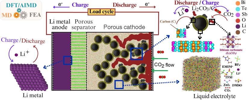
See pages - of Supporting_Information.pdf