Intense X-ray Vortices Generation via Wavefront Shaping in high-gain Free-Electron Lasers
Abstract
The x-ray vortex optical beam, distinguished by its topological charge and orbital angular momentum, offers new insights in probing complex electronic structures, enhancing material characterization, and advancing high-resolution imaging techniques. Here we propose a straightforward and effective method to generate intense x-ray vortices with tunable wavelengths in high-gain free-electron lasers (FELs). By simply adjusting the wavefront tilt of the radiation pulse during the FEL gain process, high-quality vortex beam can be amplified until saturation. Compared to existing methods for FEL vortex generation, the proposed technique imposes no wavelength limitations and can be easily implemented in high-gain FEL facilities, regardless of the operation modes.
The rapid development of vortex optical beams carrying orbital angular momentum (OAM) [1, 2] in conventional laser fields has led to numerous significant applications, including optical tweezers [3, 4, 5, 6], super-resolution imaging [7, 8, 9, 10], and quantum information processing [11]. These beams are distinguished by their unique helical phase structure, characterized by a phase singularity and an azimuthal phase dependence , where represents the topological charge indicating the number of times that vortex beam twists in one wavelength, and is the azimuthal angle. The intense potential of this specific property to transform various fields, from fundamental physics to material science and biology, has generated considerable interest [12, 13, 14, 15]. Extending OAM technology to the x-ray regime, which could offer unprecedented insights into nanoscale structures and dynamics, is particularly enticing [16, 17, 18, 19, 20]. However, conventional laser-based methods are often limited by their inability to achieve the short wavelengths required for x-ray production.
Modern free-electron lasers (FELs) have emerged as one of the most promising avenues for generating coherent x-ray sources with high intensity. The advent of FELs has represented a paradigm shift in x-ray science, providing ultrahigh brightness, femtosecond to attosecond pulse durations, and tunability across a broad spectral range [21, 22, 23, 24, 25, 26, 27, 28, 29, 30]. These attributes make FELs particularly suitable for investigating x-ray OAM. One pioneering approach to generate OAM in FELs focuses on using helical undulators, which naturally produce higher harmonics carrying OAM due to the helical trajectory of electrons within the undulator’s magnetic field [31, 32]. However, this method often results in relatively weak OAM signals at the fundamental wavelength [33]. To address this issue, a more elaborate technique has been developed, involving the interaction of a seed laser with an electron beam in a helical undulator, enabling the generation of vortex beams at the fundamental frequency. Additionally, clever methods of using seed lasers with tailored transverse phases to shape electron bunches into helical patterns, thus radiating OAM light, have been explored [34, 35, 36, 37, 38]. Although these methods show promise, they are frequently constrained by the availability and quality of seed lasers and optical elements, and often lack broad wavelength tunability. Furthermore, achieving precise control over the electron beam’s microstructure and maintaining the dominance of the OAM mode throughout the FEL amplification process remains a significant technical challenge.
In this letter, we propose a novel method for generating intense x-ray vortex beams via mode conversion in high-gain FELs. Our approach leverages the natural amplification process of FELs to produce high-quality OAM beams with tunable wavelengths. This technique offers several advantages over existing methods, including the absence of wavelength limitations and the ease of implementation in existing high-gain FEL facilities.
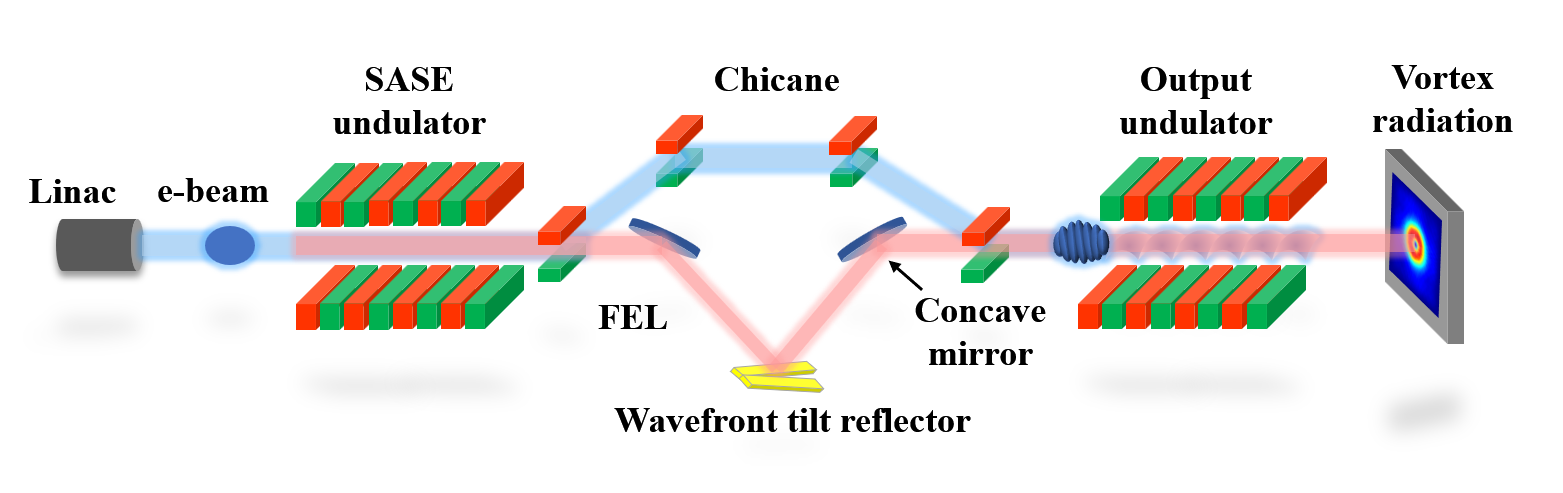
The key to the proposed method is subtly adjusting the wavefront of the radiation pulse during the FEL amplification process, leveraging diffraction effects and the FEL gain to continually twist the radiation profile into a vortex beam at saturation. The schematic layout of the proposed technique is shown in Fig. 1, where the self-amplified spontaneous emission (SASE) mode is adopted as an example to demonstrate the physical process [39, 40]. Similar to the self-seeding technique, the undulator is separated into two parts by a bypass chicane, as shown in Fig. 1(a). After sufficient amplification in the SASE undulator, the FEL pulse and the electron beam are separated in the chicane, and the transverse phase of the radiation pulse is shaped before it serves as a seed in the following output undulator.
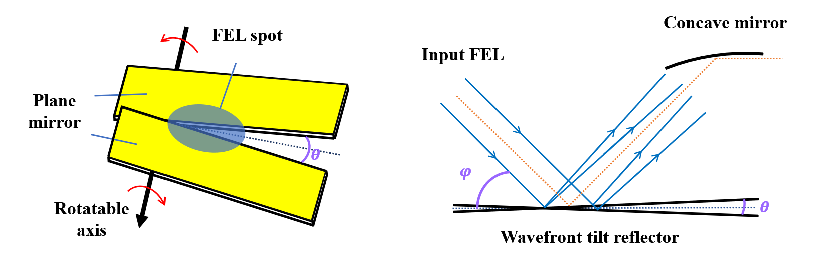
There are three optical elements in the chicane: a concave mirror to reflect the input FEL beam and adjust its position, a wavefront tilt reflector to slightly tune the wavefront tilt to shape the transverse pattern of the FEL beam, and another concave mirror to focus the output FEL beam and direct it into the following undulator. The wavefront tilt reflector consists of two plane mirrors that can be independently rotated around the same axis. The angle between the two mirrors is denoted as , as show in Fig. 1(b). We assume that is very samll and negligible compared to the incidence angle of the FEL beam. The input FEL pulse should be centrally positioned between these two plane mirrors, creating different wavefront tilts in the two halves of the FEL spot after reflection, as shown in Fig. 1(c).
The transverse phase of the output FEL pulse will be shaped due to the different optical path length. For a give position from the rotatable axis (along the dividing line of the two mirrors), the optical path difference can be represented as
| (1) |
Consequently, the variation of the transverse phase can be expressed as , where is the central wavelength of the FEL. The phase variation in the two halves of the FEL spot can be expressed as:
| (2) |
For a given optical spot projection size of the FEL beam along the dividing line, only a portion of the spot with a diameter of will interact with the electron beam in the following undulator. To achieve optical vortex radiation with a topological charge of 1 or -1, the transverse phase variation in should be around or . Hence, the required absolute tilt angle of the wavefront tilt reflector can be represented as
| (3) |
When the wavelength of the input laser changes, the tilt angle can be adjusted accordingly to maintain a constant optical transverse phase. For an input FEL pulse with a central wavelength of 5 nm, an incidence angle of 175 mrad, and an interaction range of approximately 100 m, the required is calculated to be about 8.7 rad to cover the transverse phase variation interval from 0 to .
The x-ray transport process through the concave mirror can be studied using the wave optical propagation method [41, 42]. After the concave mirror with a focal length of , the complex optical field of the radiation will be changed to
| (4) |
where denotes the wavenumber of the FEL pulse. The optical field after a propagating distance can be derived from Fresnel optics as
| (5) |
and it can be mathematically simplified to
| (6) |
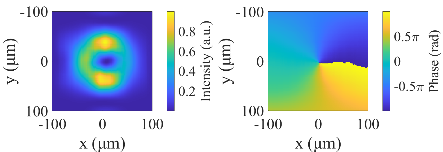
Eq. 6 indicates that the optical field in the focal plane is the Fourier transformation of the initial field, preserving its phase structure. With a focal length of approximately 3 m for the second concave mirror, the transverse intensity and phase of the FEL pulse in the focal plane are depicted in Fig. 2(a) and (b), respectively. As show in Fig. 2(b), the phase of the output FEL pulse resembles that described by Eq. 2. The upper and lower halves exhibit oppositely directed wavefront tilts, resulting in a hollow structure in the radiation intensity distribution, as illustrated in Fig. 2(a). Due to the small diffraction angle of the x-ray beam, the transverse distribution of the output FEL beam generally follows this pattern before interacting with the electron beam in the subsequent undulator.
To demonstrate the feasibility of this method for initiating coherent x-ray OAM radiation, three-dimensional simulations using GENESIS [43] were conducted, utilizing typical parameters for a soft X-ray FEL facility, as summarized in Table 1. The SASE undulator contains of five undulator segments, and the FEL peak power exceeds 3 GW at the end of the SASE undulator. Subsequently, both the electron beam and the SASE beam were then sent into the chicane. The propagation of the SASE beam was simulated using the wave optical propagation method with same optical parameters as described earlier. Here we assume a power reflectivity of for each mirror. The shaped radiation beam was then sent into the following undulator to interact with the same electron beam. The microbunching in the electron beam, formed in the previous SASE undulator, was dispersed after passing through the chicane.
| Parameters | Value |
|---|---|
| Electron beam energy | 2.5 GeV |
| Peak current | 3000 A |
| Bunch length | 80 fs |
| Emittance | 0.5 mmmrad |
| Undulator period | 4 cm |
| Undulator segment length | 4 m |
| Radiation wavelength | 5 nm |
The output undulator is resonant at the same wavelength as the SASE undulator. At the entrance of the undulator, the radiation pulse interacts with the electron beam, creating wavefront tilt microbunchings. Consequently, the evolution of the radiation profile is primarily influenced by diffraction, resulting in no power increase in the first 2 meters, as depicted in Fig. 3(a). The initial radiation wavefront does not match the characteristics of a guided FEL mode exhibiting a Gaussian intensity distribution, leading to a twisting of the transverse pattern due to diffraction and amplification within the output undulator, which produces helical microbunchings.
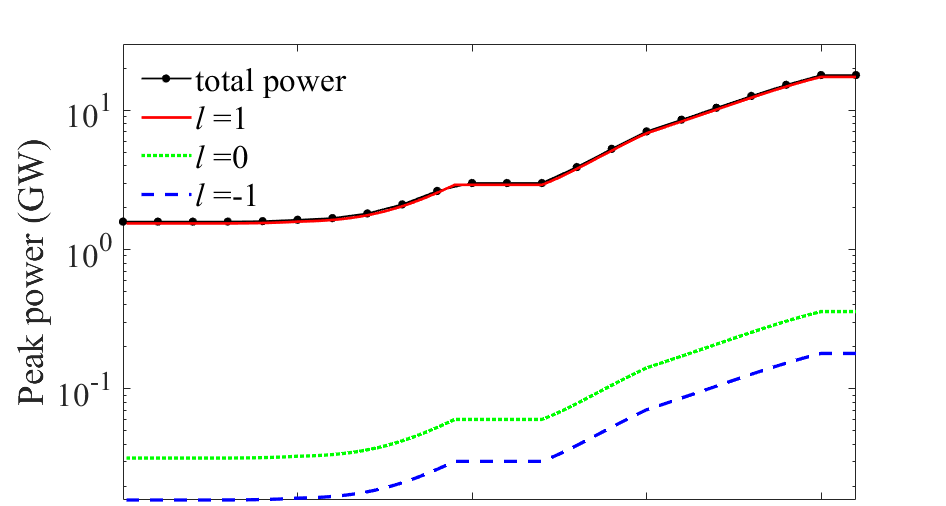
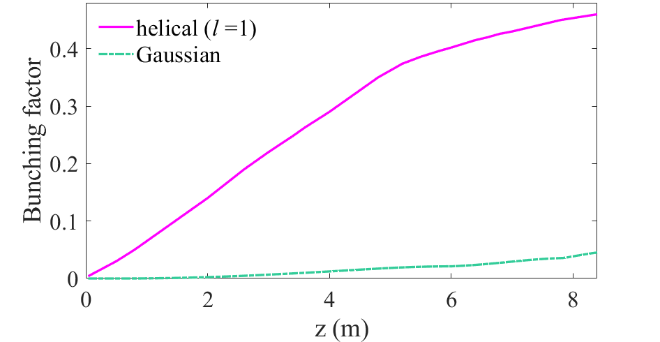
The microbunching can be quantified by the bunching factor, , where the bracket denotes averaging over all coordinates, and is the longitudinal position along the electron beam [24]. As shown in Fig. 3(b), the helical bunching factor grows from 0 to over 0.1 within the first 2 meters of the output undulator. As a result, the intensity and phase of the radiation filed begin to twist, as illustrated in the first line of Fig. 4. Following this, the FEL enters a high-gain regime where the selection of transverse modes tends to favor lower-order modes, such as the Gaussian mode () and the OAM mode with .
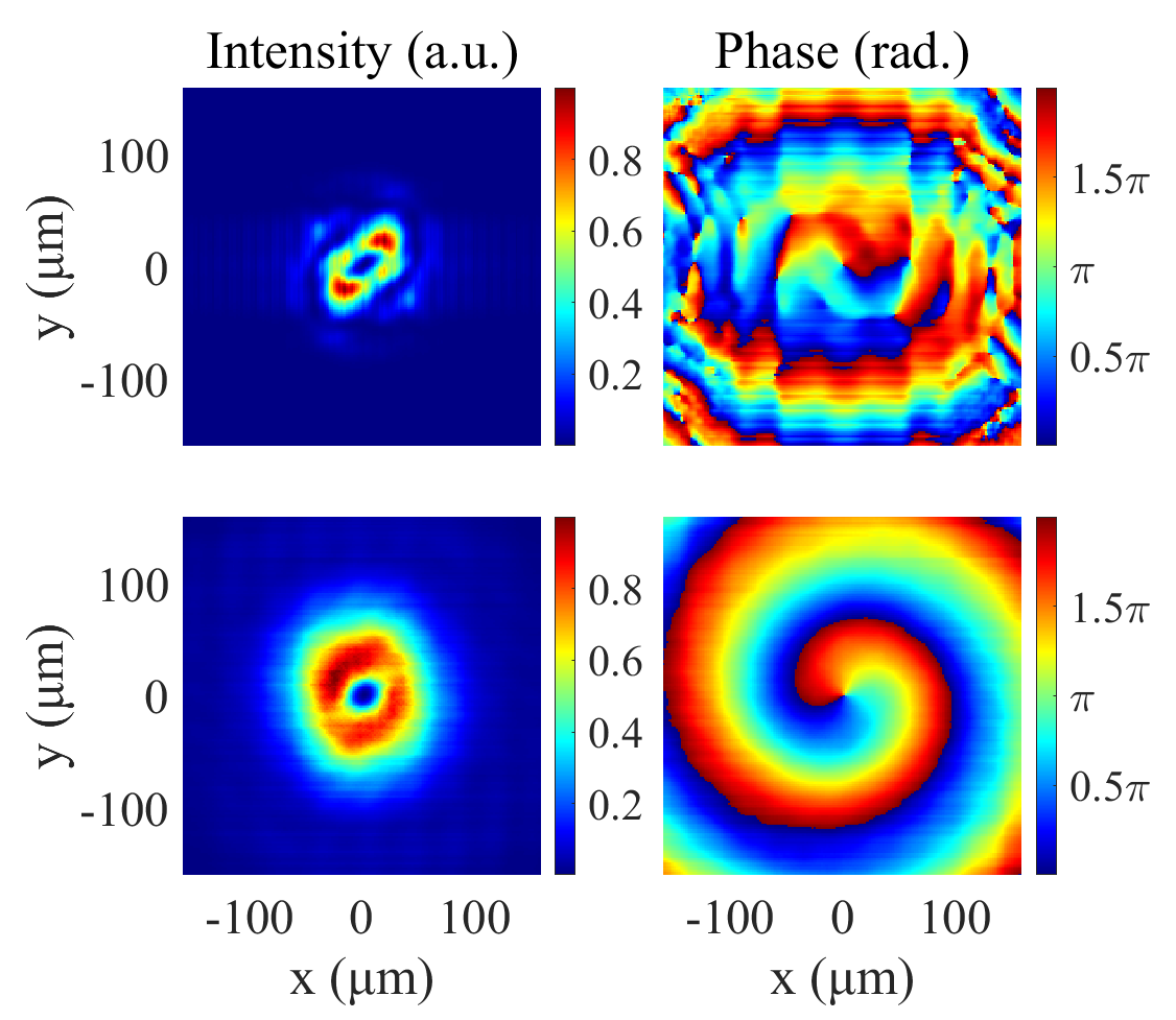
Typically, in this regime, with a sufficiently long undulator, the Gaussian mode, which has the highest growth rate, is generally the sole mode at saturation. However, the application of wavefront shaping during the gain process allows diffraction to enhance the OAM mode, facilitating its saturation much earlier than the Gaussian mode. As higher modes with reduced growth rates are eliminated, the amplification process ultimately culminates in a predominance of the guided OAM mode with at saturation, as illustrated in Fig. 3(a). The FEL peak power reaches tens of gigawatts at the exit of the output undulator, where the ratio of the mode is 97%, while that for Gaussian mode is only 2%. The characteristic hollow intensity distribution and helical phase of the vortex radiation at saturation are illustrated in the second line of Fig. 4.
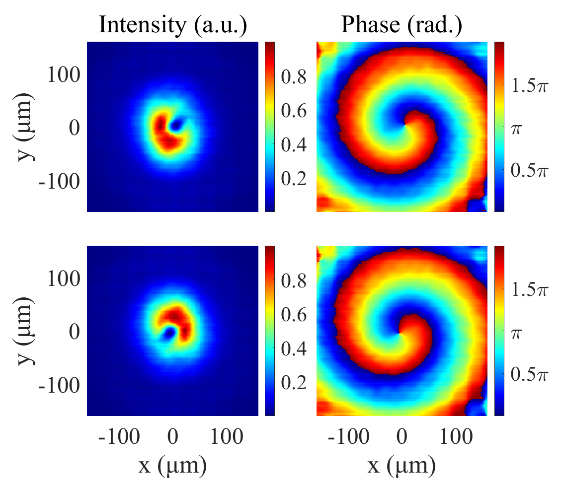
The underlying physics of the proposed method involves inducing wavefront tilts in opposite directions on either halve of the FEL spot to facilitate the rotation of the radiation phase front. In the previous design, the angle of the wavefront tilt reflector was determined according to Eq. 3. Deviations from the ideal value will not affect the trend of vortex formation but will influence the position of the optical singularity, thereby impacting the transverse symmetry of the output FEL vortex. Consequently, it is essential to analyze the adjustment precision of the wavefront tilt reflector. Multiple tests indicate that deviations should be controlled within 10%, approximately 0.87 rad in this context, to ensure optimal vortex quality. If the tilt angles exceed this threshold, the hollow intensity distribution of the optical OAM will be compromised, as shown in Fig. 5, although the phase structure may still be well-maintained. To achieve shorter wavelength vortex beams, stricter requirements for wavefront tilt adjustment precision will be necessary, necessitating careful design of the mechanical system of the x-ray beamline.
In conclusion, we have proposed a novel method to generate FEL vortices with variable wavelengths. By slightly adjusting the wavefront of the radiation pulse during the FEL gain process, the OAM mode can dominate and be amplified until saturation. This method is particularly well-suited for FEL facilities with the self-seeding setup, which naturally incorporates the necessary chicane and optical transport systems required by this approach. For applications in the hard x-ray regime, it may be essential to employ crystal transmission or reflection to achieve the required wavefront tilt. The proposed method can also be applied in the seed laser system of an external seeded FEL to control the transverse profile of the coherent high-harmonic radiation. Currently, this method is limited to generate vortex beams with topological charges of 1 and -1. However, we are actively exploring ways to extend its capabilities to produce vortices with higher topological charges through wavefront manipulation. The proposed method is not only compatible with various operational modes of FELs but also promises to deliver x-ray vortex beams of unprecedented intensity and quality, paving the way for groundbreaking research in x-ray sciences.
The authors would like to thank Hao Sun, Kaiqing Zhang, Yiwen Liu and Zhentang Zhao for helpful discussions. This work was supported by the National Natural Science Foundation of China (12122514, 12435011), CAS Project for Young Scientists in Basic Research (YSBR-115), and Strategic Priority Program of the CAS (XDB0530300)
References
- Allen et al. [1992] L. Allen, M. W. Beijersbergen, R. J. C. Spreeuw, and J. P. Woerdman, Phys. Rev. A 45, 8185 (1992).
- Shen et al. [2019] Y. Shen, X. Wang, Z. Xie, C. Min, X. Fu, Q. Liu, M. Gong, and X. Yuan, Light: Science & Applications 8, 90 (2019).
- Paterson et al. [2001] L. Paterson, M. P. MacDonald, J. Arlt, W. Sibbett, P. E. Bryant, and K. Dholakia, Science 292, 912 (2001).
- MacDonald et al. [2002] M. P. MacDonald, L. Paterson, K. Volke-Sepulveda, J. Arlt, W. Sibbett, and K. Dholakia, Science 296, 1101 (2002).
- Grier [2003] D. G. Grier, Nature 424, 810 (2003).
- Shen et al. [2012] Z. Shen, Z. J. Hu, G. H. Yuan, C. J. Min, H. Fang, and X.-C. Yuan, Opt. Lett. 37, 4627 (2012).
- Erhard et al. [2018] M. Erhard, R. Fickler, M. Krenn, and A. Zeilinger, Light: Science & Applications 7, 17146 (2018).
- Fürhapter et al. [2005] S. Fürhapter, A. Jesacher, S. Bernet, and M. Ritsch-Marte, Opt. Express 13, 689 (2005).
- Tamburini et al. [2006] F. Tamburini, G. Anzolin, G. Umbriaco, A. Bianchini, and C. Barbieri, Phys. Rev. Lett. 97, 163903 (2006).
- Nagali et al. [2009] E. Nagali, L. Sansoni, F. Sciarrino, F. De Martini, L. Marrucci, B. Piccirillo, E. Karimi, and E. Santamato, Nature Photonics 3, 720 (2009).
- Mafu et al. [2013] M. Mafu, A. Dudley, S. Goyal, D. Giovannini, M. McLaren, M. J. Padgett, T. Konrad, F. Petruccione, N. Lütkenhaus, and A. Forbes, Phys. Rev. A 88, 032305 (2013).
- Firth and Skryabin [1997] W. J. Firth and D. V. Skryabin, Phys. Rev. Lett. 79, 2450 (1997).
- Zhuang [2004] X. Zhuang, Science 305, 188 (2004).
- Wang and Chan [2014] S. B. Wang and C. T. Chan, Nature Communications 5, 3307 (2014).
- Zhao et al. [2017] Y. Zhao, A. N. Askarpour, L. Sun, J. Shi, X. Li, and A. Alù, Nature Communications 8, 14180 (2017).
- Takahashi et al. [2013] Y. Takahashi, A. Suzuki, S. Furutaku, K. Yamauchi, Y. Kohmura, and T. Ishikawa, Phys. Rev. B 87, 121201 (2013).
- Hernández-García et al. [2017] C. Hernández-García, J. Vieira, J. T. Mendonça, L. Rego, J. San Román, L. Plaja, P. R. Ribic, D. Gauthier, and A. Picón, Photonics 4, 10.3390/photonics4020028 (2017).
- De Ninno et al. [2020] G. De Ninno et al., Nature Photonics 14, 554 (2020).
- Wang et al. [2023] B. Wang, N. J. Brooks, P. Johnsen, N. W. Jenkins, Y. Esashi, I. Binnie, M. Tanksalvala, H. C. Kapteyn, and M. M. Murnane, Optica 10, 1245 (2023).
- McCarter et al. [2024] M. R. McCarter, L. E. D. Long, J. T. Hastings, and S. Roy, Journal of Physics: Condensed Matter 36, 423003 (2024).
- Ackermann et al. [2007] W. Ackermann et al., Nature Photonics 1, 336 (2007).
- Emma et al. [2010] P. Emma et al., Nature Photonics 4, 641 (2010).
- Ishikawa et al. [2012] T. Ishikawa et al., Nature Photonics 6, 540 (2012).
- Allaria et al. [2015] E. Allaria et al., Journal of Synchrotron Radiation 22, 485 (2015).
- Kang et al. [2017] H.-S. Kang, C.-K. Min, H. Heo, C. Kim, H. Yang, G. Kim, I. Nam, S. Y. Baek, H.-J. Choi, G. Mun, et al., Nature Photonics 11, 708 (2017).
- Decking et al. [2020] W. Decking et al., Nature Photonics 14, 391 (2020).
- Prat et al. [2020] E. Prat et al., Nature Photonics 14, 748 (2020).
- Feng et al. [2022] C. Feng, T. Liu, S. Chen, K. Zhou, K. Zhang, Z. Qi, D. Gu, Z. Wang, Z. Jiang, X. Li, et al., Optica 9, 785 (2022).
- Maroju et al. [2020] P. K. Maroju, C. Grazioli, M. Di Fraia, M. Moioli, D. Ertel, H. Ahmadi, O. Plekan, P. Finetti, E. Allaria, L. Giannessi, et al., Nature 578, 386 (2020).
- Duris et al. [2020] J. Duris, S. Li, T. Driver, E. G. Champenois, J. P. MacArthur, A. A. Lutman, Z. Zhang, P. Rosenberger, J. W. Aldrich, R. Coffee, et al., Nature Photonics 14, 30 (2020).
- Hemsing et al. [2009] E. Hemsing, P. Musumeci, S. Reiche, R. Tikhoplav, A. Marinelli, J. B. Rosenzweig, and A. Gover, Phys. Rev. Lett. 102, 174801 (2009).
- Hemsing et al. [2011] E. Hemsing, A. Marinelli, and J. B. Rosenzweig, Phys. Rev. Lett. 106, 164803 (2011).
- Geloni et al. [2007] G. Geloni, E. Saldin, E. Schneidmiller, and M. Yurkov, Nucl. Instrum. Methods Phys. Res. Sec. A: Accel. Spectrom. Detect. Assoc. Equip. 581, 856 (2007).
- Hemsing and Marinelli [2012] E. Hemsing and A. Marinelli, Phys. Rev. Lett. 109, 224801 (2012).
- Ribič et al. [2014] P. c. v. R. Ribič, D. Gauthier, and G. De Ninno, Phys. Rev. Lett. 112, 203602 (2014).
- Rebernik Ribič et al. [2017] P. c. v. Rebernik Ribič, B. Rösner, D. Gauthier, E. Allaria, F. Döring, L. Foglia, L. Giannessi, N. Mahne, M. Manfredda, C. Masciovecchio, et al., Phys. Rev. X 7, 031036 (2017).
- Sun et al. [2021] H. Sun, X. Wang, C. Feng, L. Tu, W. Fan, and B. Liu, High Power Laser Science and Engineering 9, e65 (2021).
- Yan and Geloni [2023] J. Yan and G. Geloni, Advanced Photonics Nexus 2, 036001 (2023).
- Kondratenko and Saldin [1980] A. M. Kondratenko and E. L. Saldin, in Generating of coherent radiation by a relativistic electron beam in an undulator (1980).
- Bonifacio et al. [1984] R. Bonifacio, C. Pellegrini, and L. Narducci, Optics Communications 50, 373 (1984).
- Goodman [1969] J. W. Goodman, in Introduction to Fourier optics (Roberts and Company, 1969).
- Serkez et al. [2015] S. Serkez, J. Krzywinski, Y. Ding, and Z. Huang, Phys. Rev. ST Accel. Beams 18, 030708 (2015).
- Reiche [1999] S. Reiche, Nucl. Instrum. Methods Phys. Res. Sec. A: Accel. Spectrom. Detect. Assoc. Equip. 429, 243 (1999).