Incentive Mechanism and Path Planning for UAV Hitching over Traffic Networks
Abstract
Package delivery via the UAVs is a promising transport mode to provide efficient and green logistic services, especially in urban areas or complicated topography. However, the energy storage limit of the UAV makes it difficult to perform long-distance delivery tasks. In this paper, we propose a novel multimodal logistics framework, in which the UAVs can call on ground vehicles to provide hitch services to save their own energy and extend their delivery distance. This multimodal logistics framework is formulated as a two-stage model to jointly consider the incentive mechanism design for ground vehicles and path planning for UAVs. In Stage I, to deal with the motivations for ground vehicles to assist UAV delivery, a dynamic pricing scheme is proposed to best balance the vehicle response time and payments to ground vehicles. It shows that a higher price should be decided if the vehicle response time is long to encourage more vehicles to offer a ride. In Stage II, the task allocation and path planning of the UAVs over traffic network is studied based on the vehicle response time obtained in Stage I. To address pathfinding with restrictions and the performance degradation of the pathfinding algorithm due to the rising number of conflicts in multi-agent pathfinding, we propose the suboptimal conflict avoidance-based path search (CABPS) algorithm, which has polynomial time complexity. Finally, we validate our results via simulations. It is shown that our approach is able to increase the success rate of UAV package delivery. Moreover, we estimate the delivery time of the UAV in a pessimistic case, it is still twice as fast as the delivery time of the ground vehicle only.
Index Terms:
Crowdsourcing, UAV hitching, Minimal-connecting tours, Conflict avoidance.I Introduction
I-A Background
In recent years, the continuous expansion of the e-commerce market has promoted the rapid development of the express logistics industry [1]. Especially during the epidemic, people’s living habits have changed dramatically in order to maintain social distance. New logistics service models have emerged in order to avoid face-to-face contact, such as non-contact delivery [2]. However, the rapid development of urban logistics has also brought a series of problems, such as traffic congestion, air pollution, low logistics efficiency [3]. Due to its agility and mobility, the delivery services enabled by the Unmanned Aerial Vehicle (UAV) are not restricted by terrain and traffic conditions, which can freely pass through urban region during rush hours to provide logistics services flexibly and efficiently. Many companies all over the world have launched commercial UAV delivery services, such as Amazon, Google, and UPS in the United States, DHL in Germany, and JD, SF-express in China [4]. However, due to the limitation of UAV energy capacity, current UAV logistics services are limited to short-distance delivery [5]. Therefore, how to expand the range of UAV delivery services is an urgent problem to be solved.
With the development of new technologies such as 5G, Internet of Things (IoT), and Artificial Intelligence (AI), crowdsourcing, as a mode of using large-scale network users to assist in specific tasks, has received more and more attention from different application platforms, and has been widely used in various scenarios, such as food delivery riders, car sharing, and data cleaning, etc [6]. Inspired by the crowdsourcing model, the ground vehicles such as trucks can be utilized to offer riding for the UAVs, which greatly saves the battery consumption of UAVs and extend their delivery distance. Amazon has proposed a UAV-truck riding strategy to allow UAVs to land on transportation vehicles from different shipping companies for temporary transport, by making an agreement with the owner of the transportation vehicles [7]. In addition, the technology of docking UAVs on stationary or high-speed moving vehicles is relatively mature [8, 9], which lays the foundation for the development of air-ground collaborative multimodal logistics system.
However, this new multimodal logistics system based on crowdsourcing faces the following challenges:
-
•
Incentives for ground vehicles’ cooperation. The provision of hitch services by ground vehicles is the basis for the implementation of multimodal logistics systems. However, the ground vehicles incur hitching costs (e.g., fuel consumption) when offer riding service, and they should be rewarded and well motivated to assist UAV delivery. Moreover, the ground vehicles are heterogeneous in nature. They will randomly arrive the targeting interchange point and their private costs for offering riding service are different and unknown. Thus, the pricing design under the incomplete vehicle information is challenging. In addition, a higher monetary reward leads to a shorter vehicle response time (i.e., UAV waiting time), which improves the delivery efficiency of multimodal logistics system. For sustainable management of the multimodal logistics system, the pricing strategy should be dynamic to best balance the payment to ground vehicles and their response time.
-
•
Crowdsourcing-based multimodal logistics system modeling under time-varying traffic networks and UAV energy constraint. By integrating the UAVs with the ground vehicles, the UAVs should decide where to hitch on ground vehicles and whether hopping between different vehicles to complete one delivery task, which creates large number of interchange points on the basis of the road network for path planning. Moreover, due to the mobility of ground vehicles and the instability of traffic conditions, the modeling of the integrated system is challenging.
-
•
Design of fast and efficient task allocation and path planning algorithms for the multimodal logistics system. The ground vehicles’ arrivals and response time in the vicinity of the UAVs at a certain time are unknown. In addition, the path planning of the UAVs should be carefully designed to prevent conflicts between UAVs, such as multiple UAVs landing at the same vehicle at the same time. Such combinatorial optimization problems are often NP-hard problems and challenging to solve.
I-B Main Contributions
To tackle the above challenges, a two-stage model is proposed to jointly analyze the incentive mechanism design for ground vehicles and path planning for UAVs. We summarize our main contributions as follows:
-
•
Crowdsourcing-based multimodal logistics system modeling. To our best knowledge, this paper is the first work studying the crowdsourcing-based multimodal logistics system, in which the ground vehicles are invited to offer hitching services for UAVs. Such multimodal logistics system effectively extends the range and efficiency of UAV deliveries. We formulate this system as a two-stage model to jointly study the incentive mechanism design for ground vehicles and path finding for UAVs. In Stage I, a dynamic pricing scheme is proposed to motivate the ground vehicles to assist UAV delivery under the incomplete information about the ground vehicles’ random arrivals and private hitching costs. In Stage II, the task allocation and path planning of the UAVs over traffic network by considering the UAV energy constraint and the conflicts between UAVs.
-
•
Dynamic pricing for ground vehicle under incomplete information. To balance the payment to ground vehicles and their response time for efficient delivery, a optimal dynamic pricing scheme is proposed under incomplete information case regarding ground vehicles’ random arrivals and private hitching costs. We prove that if the vehicle response time is long, a high price offer should be decided to encourage the ground vehicles to assist delivery. According to the proposed dynamic pricing, the vehicle response time for each interchange station can be predicted and utilized for the path planning in Stage II.
-
•
Algorithm Design for fast and efficient task allocation and path planning. To reduce the computation complexity, the deployment of UAV delivery tasks is split into two layers. In task allocation layer, we propose a near-optimal algorithm with polynomial computation complexity to generate the delivery sequence. In path planning layer, to avoid the computational burden due to the order-of-magnitude increase in conflicts, we propose a conflict avoidance-based path search algorithm and prove that the bounded suboptimal paths for all UAVs can be obtained in polynomial time.
I-C Related work
The access path planning problem for UAVs can be viewed as the Traveling Salesman Problem (TSP) [10, 11]. This type of combinatorial optimization problem is a classical NP-hard problem. Once the order of package delivery for all UAVs is found, the system begins to find the optimal delivery path for each UAV. Classical algorithms such as or Dijkstra for solving the shortest path are often used to solve the optimal UAV trajectory problem [12, 13]. In addition, control theory is also utilized for modeling and solving UAV path planning problems [14, 15]. The constraints of UAV energy storage and conflicts between UAVs make the UAV path planning problem more challenging, which is NP-hard to get the optimal solution. Some methods such as Conflict-based search (CBS) [16], have been shown to be efficient methods to solve this Multi-Agent Path Finding (MAPF) problem.
Utilizing the ground vehicles to extend the UAVs’ delivery range has attracted wide attentions from both academia and industry. The researchers in Stanford University have shown that combining UAVs with the existing transit network can increase the delivery coverage of UAVs by up to [17]. However, using buses for UAV delivery lacks fault tolerance. For example, the bus schedules may not be accurate. If the UAV happens to miss the arrival time of the current bus, the UAV needs to wait longer for the next bus to arrive, or has to change its route, which may cause the delivery task to fail. In the crowdsourcing-based system considered in this paper, the request is sent to the ground vehicle at the time when the UAV needs the hitching service and any passing-by ground vehicle along the UAV’s routes can be the UAV carrier, so there is no case of missing a vehicle. E-commerce giant Amazon has proposed in its patent that commercial vans from different operators can be used to assist UAVs in delivery services [7]. However, this is also based on the pre-signed agreement with the van operators. The number of available commercial vans is limited and cannot cover the entire transportation network, which will greatly reduce the efficiency of UAV delivery. In this paper, the ground vehicles (such as trucks, buses) with wide coverage are added to the logistics network based on crowdsourcing technology, which helps keep the waiting time for UAVs to a minimum.
The rest of this paper is organized as follows. The system model is given in Section II, in which the multimodal logistics system is formulated as two stages. In Section III, the incentive mechanism for the crowdsourcing-based hitching services is designed in Stage I. Sections IV and V discuss the task allocation and multi-agent path finding for the UAVs in Stage II. Section VI validates our results via simulations. Section VII concludes this paper.
II System Model
In this paper, we aim to solve the UAV’s limited flight range problem caused by its energy constraint in the process of delivery. We propose an efficient multimodal logistics system to improve the delivery range of UAVs, in which a crowdsourcing mechanism is implemented by inviting the ground vehicles (trucks, buses, etc.) to offer the hitch service for UAVs.
II-A Problem
Consider a logistics system with UAVs performing delivery tasks to known delivery addresses from depots. Denote the set of delivery addresses as and the set of depot locations as . We assume that any package can be dispatched from any depot and the depot can also charge or change the battery of the UAV quickly. When a UAV delivers a package from a depot to a delivery location, the UAV can call a vehicle on the ground to provide a hitch service, which significantly extends the UAV’s delivery range. In order to facilitate management, we specify that the UAV can stop and wait for ground vehicles only at specific interchange points equipped with surveillance cameras for safety’s sake. We generate potential interchange routes on the traffic network starting and ending at certain interchange points, where the UAV can wait for ground vehicles while performing delivery tasks. The set of interchange points is denoted as ().
In the crowdsourcing-based multimodal logistics system, the goal is to (i) design the optimal dynamic pricing to deal with the tradeoff between the payment to ground vehicles and UAVs’ waiting time; (ii) find the delivery path of each UAV to deliver all packages in a reasonable combination of UAVs’ own flight path and transit routes on the traffic network, while minimizing the maximum delivery time for each UAV without exceeding the storage capacity limit of the UAV.

II-B Approach
In a crowdsourcing-based air-ground collaborative logistics system, the behavioral decisions of the ground vehicles will affect the UAV transportation efficiency. If the UAV waits long time for the ground vehicles’ response to assist in transportation, the passage time of the corresponding road section will be prolonged, which will lead to the delay of UAV mission completion time. Therefore, it is crucial to design an effective crowdsourcing incentive mechanism to encourage the ground vehicles to assist delivery. The passage time of each road section will also influence the design of subsequent task allocation and path planning algorithms. However, higher incentives can shorten the UAV waiting time, but cause an increase in UAV platform’s cost. Therefore, we will design a dynamic pricing scheme to best balance the reward expenditure to ground vehicles and the expected vehicle response time of each road section.
Completing all package delivery requests means that each package needs to be assigned to one and only one UAV. So this problem can be viewed as a variation of the traveler problem. Because of the limitations of UAV carrying capacity and energy storage, we specify that a UAV can only deliver one package at a time and return to some depot for charging after completing the delivery task (charging time for UAVs is ignored here). The delivery time of a package by a UAV consists of the UAV flight time and the ride time including the vehicle response time (i.e., UAV waiting time) and the vehicle traveling time when carrying the UAV. We describe the energy storage limit of each UAV as a maximum flight time constraint, and each UAV must not exceed the maximum flight time when performing its delivery tasks. In addition, to avoid collisions between UAVs, multiple UAVs can’t land at the same interchange point at the same time. The above joint optimization problem for UAV-vehicle path planning can be modeled as mixed integer linear programming. However, most of the existing mixed integer linear programming algorithms can only handle small-scale models, which are not suitable for large number of UAVs/packages and vast traffic network scenarios. We decompose the joint path planning problem into two layers of decision models for discussion, and design algorithms with low computational complexity at each layer, respectively.
We formulate our multimodal logistics system as two stages as shown in Fig. 1. In stage I, we predict the vehicle response time at each interchange point based on our designed dynamic pricing scheme, and update this information into the time weights of the interchange routes in the traffic network for the following path planning. In Stage II, we first analyze the task allocation of UAVs to solve the problem of which UAV delivers which packages and the order of delivery between packages, and then the path finding for each delivery subtask. To be specific, for task allocation in Layer 1, we temporarily ignore the specific route of the UAV from the depot to the package delivery address. We only decide which packages are sent from which depot and which UAV is responsible for which series of packages to be delivered, depending on the estimated time (the shortest path from a certain depot to the destination) between the depot and delivery location. We use linear programming algorithms with relaxation conditions that accomplish the task allocation problem in polynomial time. For path finding in Layer 2, we take one UAV to deliver a package from a depot and then return to a depot as a subtask, and perform route planning for the UAV fleet to execute the allocated delivery subtask. To avoid collisions between multiple UAVs, only a limited number of UAVs are allowed to stay at each interchange. We adopt the idea of CBS to design an efficient MAPF algorithm called conflict avoidance-based path search (CABPS), i.e., each UAV jointly maintains the same list of interchange occupancy information and performs its own path planning based on this constraint.
II-C Framework And Workflow
In Stage I, we motivate the ground vehicles to offer riding for UAVs by proper incentive mechanism design, e.g., monetary reward. However, the ground vehicles are mobile and their private costs for carrying the UAVs for certain distance is unknown. Under this circumstance, the waiting time for the UAVs to call for ground vehicles at different interchange points at different time is variable and unknown. In the following, we design a dynamic pricing scheme to balance the response time of ground vehicles and the monetary payment under the incomplete information about the ground vehicles’ random arrivals at certain interchange point and private carrying costs. On the basis of the designed dynamic pricing scheme, the expected response time of ground vehicles at each interchange can be generated, which will be taken into consideration when performing path planning for each UAV.
In Stage II, we propose a comprehensive algorithm UAV-Task-Allocation-Path-Planning for building an efficient air-ground cooperative multimodal logistics system. It guarantees a near-optimal solution in polynomial time. Our goal is to plan delivery paths for UAVs after accepting requests for packages.
The detailed design is given in Algorithm 1. Denote the traffic network graph as , where the vertex set , and each directed edge for every contains a weight denotes the passage time from to and an attribute denotes the power consumption of the UAV from to . We divide the directed edges into two types, one is the flight edge, which indicates that the UAV flies from to . The other is the transit edge, which indicates that the UAV hitches a ground vehicle from to . It is worth mentioning that if the directed edge is a transit edge, its power consumption is . Relatively, it has a longer passage time (the passage time from to includes the UAV’s waiting time and the carrying time from to ) than the flight edge.
Layer 1 (line 1): Task Allocation is the first layer of our algorithm, which takes the traffic network graph , the set of depot location , the set of package locations , and the number of UAVs as inputs, returns the set of UAV paths , where indicates the delivery subtask for the UAV. Each subtask consists of three values: starting depot, package address and returning depot.
Layer 2 (lines 2-10): The second layer Multi-Agent-Path Finding uses the Conflict Avoidance Based Path Search (CABPS) algorithm to calculate the path for each UAV separately. CABPS takes the subtask delivered by the UAV, the current waiting time estimate for each interchange and the occupancy time of each interchange as inputs, it gives the specific delivery path for each UAV’s subtask .
Our system eventually returns the set of delivery path for all UAVs. refers to the path planned by the UAV performing its own delivery subtask, and we use to indicate the total time taken by the UAV to complete all its delivery tasks. The purpose of our algorithm is to minimize . Note that in the second layer of the algorithm, the paths for all delivery subtasks of the UAVs are not computed simultaneously. The delivery subtask of each UAV is computed successively once the previous subtask is accomplished, by considering the conflicts between UAVs. In the following sections, we will describe the design of the dynamic pricing mechanism and the two-layer algorithms in more detail.
III Stage I: Mechanism Design for Ground Vehicle Crowdsourcing
In this section, we will discuss the incentive mechanism design for crowdsourcing at a typical interchange point. Consider a discrete time horizon with time slot . When the UAV arrives at the interchange station, it sends the request and pricing reward to nearby vehicles. We use to denote appropriate crowdsourcing vehicles’ (such as trucks, buses, etc.) arrivals at certain interchange point at time , and otherwise. The probability of can be viewed as the traffic density (e.g., number of vehicles per meter, ) at this interchange point. The vehicle decides whether to accept the current price and provide hitching service according to its private cost for carrying the UAVs, where the upper bound is estimated from historical data. In this paper, we consider non-trivial traffic density . Otherwise, the UAV platform should always set the price to be the upperbound to encourage the rarely arriving ground vehicles to provide hitching services.
The vehicle response time at time starting from the moment the UAV sent hitching requests (i.e., ) is affected by the traffic density and the dynamic pricing . If a ground vehicle appears at time (i.e., ) and its carrying cost is less than the offered price (i.e., ), the vehicle will provide hitching service. Otherwise, the vehicle response time at time increases from to . Therefore, starting from time slot with initial UAV waiting time , the dynamics of the vehicle response time is as follows:
| (1) |
According to the Cumulative Distribution Function of the vehicles’ private costs and the traffic density at the interchange point, the probability of crowdsourcing vehicles accepting hitching service at time slot is . Therefore, at time slot , the conditional expectation of the vehicle response time is:
| (2) | ||||
Denote . Thus, the dynamics of the expected response time can be obtained as follows:
| (3) |
At each time slot , the expected payment to the ground vehicle is . In order to maximize the benefits of the platform, the dynamic price should not exceed the maximum private cost of the vehicle. Consider the uniform CDF of vehicles’ private costs, i.e., . The goal of the UAV platform is to design dynamic prices , to minimize the summation of total expected payment and vehicle response time:
| (4) |
| (5) |
where is the discount factor.
The above dynamic programming problem is not easy to solve by considering the huge number of price combinations over time. In the following, we will analyze the optimal solution to this dynamic problem by using dynamic control techniques.
Proposition III.1


| (6) |
with , and the vehicle response time at time is
| (7) |
where
| (8) |
| (9) |
with , , on the boundary.
Proof: Denote the cost objective function from initial time as
| (10) |
and the value function given the initial response time as
| (11) |
Then, we have the dynamic programming equation at time :
| (12) | ||||
| (5) |
According to the first-order condition when solving (12) in the backward induction process, we notice that is a linear function of . Thus, the value function in (12) should follow the following quadratic structure with respect to :
| (13) |
yet we still need to determine . This will be accomplished by finding the recursion in the following.
First, we have on the boundary due to . Given as in (13), the dynamic programming equation at time is
| (14) | ||||
Substitute in (5) into (14) and let , we obtain the optimal price in (6). Then, we substitute in (6) into in (14), and obtain as a function of and . Finally, by reformulating in (14) and noting that , we obtain the recursive functions of and in (8) and (9). Substitute in (6) into (5), we obtain the expected age in (7).
Figs. 2 and 3 simulate the system dynamics over time under the optimal dynamic price in (6). We can see that is low initially, allowing a modest increase in the response time to save the UAV platform’s costs. The price then increases with the increased response time to encourage the ground vehicles’ help until both of them reach steady states. This is consistent with the monotonically increasing relationship between and in (6). However, when approaching the end of the time horizon , the price drops to without worrying about its effect on the future waiting time. As a result, the vehicle response time increases again but lasts only a few time slots.
| (15) |
| (16) |
Proof: Starting from the boundary condition , according to in (8) and in (9), we can obtain and backward given and at next time slot. Rewrite above as
| (17) |
Starting from and note that , we have . Note that (17) is increasing with and , we can conclude that is bounded increasing sequence in the reverse time order and will converge to the steady-state , which can be solved as (15) by removing the time subscripts from (8).
By removing the time subscripts from (9), the stead-ystate is solved as in (16). In the following, we will show that is bounded increasing sequence in the reverse time order and converges to . According to in (9), define as the right-hand side of (9) given the steady-state , i.e.,
| (18) |

Take the derivative of with respect to , we have
| (19) |
According to , we have . Thus, and increases with . Since is an increasing sequence and converges to , .
Starting from , we have . Since increases with , the equation set intersects with the vertical axis with . The slope of each equation satisfies . Therefore, starting from , we have based on . Then, from , we have based on . Thus, we can obtainuntil .
Fig. 4 simulates the dynamics of in (8) and in (9). We can see that both and fast converge to their steady-states in a few rounds. In the following, we will show the steady-state of the dynamic pricing in (6) for infinite time horizon case.
Remark III.1
For the infinite time horizon case, the optimal dynamic pricing is simplified from (6) to
| (20) |
and the vehicle response time at time is
| (21) |
As , according to in (15) and in (16), and note that , the vehicle response time converge to the steady-state :
| (22) |
and the optimal dynamic pricing converges to
| (23) |
which shows that always holds when .
IV Stage II: Layer 1: Task Allocation
IV-A Algorithm Overview
This section focuses on the first layer of the stage II. We design the UAV task allocation scheme to traverse all packages and minimize the maximum delivery time of each UAV. Package nodes and the depot nodes in the traffic network graph are picked out to generate the task allocation graph, which is denoted as , where the set of vertices , and the weight of directed edge is the predicted passage time from position to position . We run the shortest path search algorithm in the traffic network graph to obtain the predicted passage time between all points of the task allocation graph . We solve such a problem in to find a shortest path to access all packages, which means we find the delivery sequence of all packages and it has the smallest total predicted passage time.
This layer aims to design the task allocation scheme to minimize the longest UAV task completion time, i.e., , where is the total time for the UAV to complete the corresponding package delivery service and return to depot under task allocation from depot in delivery order . Task allocation contains the information of which UAV delivers which packages and the delivery order. To find the task allocation scheme for UAVs, we first consider the minimum connection tours (MCT) problem that connects all packages:
| (24) |
| (25) | ||||
| (26) |
| (27) |
| (28) |
where constraint (25) indicates that each package address must be visited once and comes from one depot, and the UAV must return to one depot after completing delivery. Constraint (26) indicates that the UAVs entering and exiting each depot are equal, which paves the way for subsequently transforming this problem into a minimum cost circulation problem and designing algorithms in polynomial time. Constraint (27) indicates that the edge connected to the package address is used at most once. The last constraint (28) indicates that multiple round trips between depots are possible.
The detailed design is given in Algorithm 2, in which we aim to minimize the sum of the estimated passage time between depots and packages while ensuring that each package is dispatched by one and only one depot.
SubGraph. At the task allocation layer, we seek a set of paths that minimize the maximum delivery time of any UAV. Here we ignore the specific routes from the depot to the package and only consider how they are connected. A new task allocation graph is generated from the network based on the known geographic locations of depots and packages, contains only the nodes of depots and packages, and the weights between them are the estimated passage times between the two locations.
MinimumCostCirculation (MCC). The problem can be viewed as an minimal visiting paths problem[11] and is NP-hard. Note that the structure of the minimal visiting paths problem is very similar to the MCC problem, and the latter can be solved by a polynomial-time algorithm[18]. In problem , indicates the number of times to select the edge , which is an integer. To reduce the computational complexity of the linear programming problem, we transform the integer constraints of the combinatorial optimization problem into real numbers, thus transforming the problem into a MCC problem for analytical solution. Finally, we divide the minimum connected path obtained by linear programming into paths for each UAV.
GetStrongConnectedComponent. The solution , , given by MCC shows the number of times the edge is used in the task allocation graph . The depot nodes are connected to the package nodes according to the edges used and forming multiple connected components. Then we combine all the connected components to generate the entire connected graph, which has edges covering the trips we need to traverse all the packages with the least cost.
SplitTours. After obtaining the trip that traverses all the packages with minimum cost, we distribute it evenly among all the UAVs. Evenly means that the estimated time of package delivery undertaken by each UAV is close to the total estimated time divided by the total number of UAVs . The estimated package delivery time is not equivalent to the actual UAV delivery time. The time spent by the UAV includes the flight time, carrying time (hitching time), waiting time (vehicle response time), and the time spent by the UAV for conflict resolution.
IV-B Computational complexity and optimality
Since we relax the variable in linear programming from an integer constraint to a real number constraint, the MCT problem is converted to a MCC problem. For the MCC problem, we can compute an integer optimal solution in polynomial time[18, 19].
Our goal is to minimize the maximum delivery time of UAVs, by returning the set , where indicates the sequence of package delivered by the UAV. Then our objective can be expressed as
| (29) |
Let the optimal task allocation set be , where . In the task allocation algorithm, linear programming usually returns more than one connected component, and we aim to find the minimum weights of the edges between depots to connect different connected components, which finally generates a strongly connected path over the graph. Such a path traverses all the packages from a depot and then back to a depot, and contains the newly added edges (the depot to another depot), which makes our result slightly deviate from the optimal solution. We observe that
| (30) | ||||
where is the total weights of the paths and is the number of times to merge the connected components. We assign a task to each UAV by specifying that its package delivery prediction time is less than the total prediction time divided by total number of UAVs . The worst outcome of this is that a UAV is assigned an additional task after it has been assigned exactly the average prediction time, such that we can derive that
| (31) |
We find that the predicted time undertaken by any one UAV in this layer of the algorithm does not exceed the average predicted time plus the estimated time for one maximum package delivery time. Combining the above equations, we finally get the gap between our results and the optimal solution:
| (32) |
where , . Obviously, as the number of UAVs and the number of package delivery requests rises, our result gets closer to the optimal solution and solves in polynomial time.
V Stage II: Layer 2: Multi-Agent Path Finding
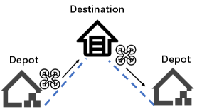
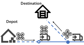
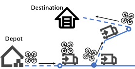
According to the task allocation results of the UAVs in the first layer, the task of each UAV can be decomposed into a series of delivery subtasks, i.e., delivering packages from depot to destination and back to the same or different depot . The conflict between UAVs comes from the space limitation of the ground vehicles and interchange points. Here, we define as only one UAV can stay at an interchange point at the same time to wait for ground vehicles.111Our algorithms can be extended to the case with more than one UAV staying at an interchange point at the same time, and the simulation result is shown in Section VI. Based on whether the UAVs hitch on ground vehicles and whether hop between different ground vehicles for each subtask, we discuss the following three types of UAV delivery networks as shown in Fig. 5 (a) direct flight network (b) single-hop hitch network (c) multi-hop hitch network.
V-A Direct Flight Network
In a direct flight network, UAVs are utilized for delivering packages without the help of ground vehicles. In this case, we consider that the UAVs deliver packages by flying from the depot to the package address directly, and thus the delivery time of a UAV is equal to the straight-line distance from the depot to the package address divided by the UAV’s average flight speed. Though delivering directly by UAVs saves a lot of time especially during peak hours or in an a complex geographical environment, the energy limitation of the UAVs has restricted their service range. In the direct flight network, for each package delivery request executed by the UAV, we need to consider the constraint that whether the flight distance consumed in the whole journey exceeds its own limit. When the UAV cannot reach the designated location, we consider the delivery mission to fail. The multimodal logistics system can solve the flight distance limitation of direct flight network, and we compare the mission delivery failure rates of the three networks in Section VI later.
V-B Single-Hop Hitch Network
In a single-hop hitch network, the UAV hitch on a ground vehicle only once during the journey. For a delivery subtask of , the UAV can depart from the depot , fly to the interchange point to wait and hitch on the vehicle through the transit section , and then fly from to the delivery destination . After completing the subtask, it returns to the depot in order to perform the next subtask. Denote the passage time of the UAV from the depot to the package address be , where and are the corresponding UAV flight time (which can be obtained from the UAV speed) and is the ride time. Based on the crowdsourcing incentive mechanism, the vehicle response time for the transit section is predicted to be . So the ride time is , where is the vehicle passage time for section (which can be obtained from the average vehicle speed). We decompose one delivery subtask into two segments and . The transit sections and can be the same or different sections. The transit sections are directed edges and the set of all transit sections is . With the objective of minimizing delivery subtask completion time, the UAV hitch problem is modeled as
| (33) | |||
| (34) |
| (35) | |||
| (36) | |||
| (37) |
where constraint (34) indicates that the UAV that selects a transit section cannot exceed its capacity (no more than UAVs can stay at an interchange point at the same time), thereby avoiding UAV conflicts. The constraint (35) indicates that only one transit section can be selected from to and from to . And constraint (36) indicates that the total flight time of the UAV cannot exceed its maximum flight time , where is the flight time of the UAV that selects section .
A delivery subtask of can be divided into two parts: from to and from to . Thus each UAV needs to invoke the path finding algorithm twice with half the energy constraint each time to perform a subtask and the detail of single-hop path finding is given in Algorithm 3. The algorithm takes the departure location , destination and interchange sections as inputs. Single-Hop Path Finding algorithm only has to traverse all the interchanges once to find the path that takes the shortest time and does not exceed the UAV’s flight limit.
V-C Multi-Hop Hitch Network
In multi-hop hitch networks, UAVs can extend their delivery range by hopping between more than one ground vehicles in one delivery task, which makes the path finding problem more challenging due to more combinations of transit sections. When performing path planning, UAVs need to consider their own flight distance limitations and the conflicts between UAVs. CBS can solve the conflict problem between UAVs. It first ignores the conflict between UAVs in the upper layer and finds the optimal path for each UAV, then detects whether there is a conflict between the paths of each UAV in the lower layer. If a conflict occurs, CBS adds a new restriction and runs the path planning algorithm in the upper layer again. However, multiple agents operate on the same traffic network, and whenever a conflict is detected between UAVs, a new conflict restriction needs to be added for each conflicting UAV and a new path is planned for each UAV again. As the number of UAVs and the number of package delivery requests increases, the number of conflicts between UAVs will become larger and larger. Thus, the system will frequently plan new routes for UAVs, leading to degradation of network performance [16].
To deal with the performance degradation of CBS, we propose a conflict avoidance-based path search algorithm for the path optimization problem under multi-hop hitch network, which can be solved in polynomial time. Firstly, we search for the shortest path for UAVs by heuristic algorithm. When a UAV determines a clear path, we want to make sure other UAVs don’t clash with it. So the system will updates the information about the occupied interchange points in the network as it plans the path for each UAV, and that occupancy information needs to be taken into account when planning paths for other UAVs. Thus we are able to ensure that no conflicts occur in the network. The detail of CABPS is given in Algorithm 4. The inputs to the algorithm are the entire network graph , the departure location , destination point , the vehicle response time of each interchange predicted based on the crowdsourcing incentive mechanism and the information about the current timestamp of each interchange being occupied.
Step 1 (lines 1-2): Construct a new path search graph from the original graph based on the departure node and end node of the current subtask, where . We connect such edges like that , for any edge with two properties, one is the passage time spent from to , and the other is the UAV flight time consumed. We define the path search graph as follows.
Definition V.1
There is only one depot node and one package node in the path search graph , and the rest are interchange points. For an edge , its properties are divided into the following cases: (i) If one of and is a depot or package node, the passage time of the edge is the straight-line distance from to divided by the average speed of the UAV, and the consumption time of the edge is the flight time of the UAV. (ii) If both and are interchange points and the edge is a transit route, the passage time of the edge is the distance of the journey from to divided by the average speed of the vehicle, and the consumption of flight time is . (iii) Both and are interchange points, but the edge is not a transit route. The passage time of this edge is the straight-line distance from to divided by the UAV speed and the consumption time of the edge is the flight time of the UAV.
Step 2 (lines 3-17): Use the heuristic algorithm[20] to search for the shortest path in the subgraph . uses a priority queue to store the information of historical paths from start node to the candidate nodes, and the heuristic function is the shortest path search algorithm from the current node to the destination node. In the path search process, we save the paths that do not consume more flight than the limit, and the passage time consumed by the current path includes the delivery time, waiting time at the interchange and the additional waiting time due to conflict avoidance.
Step 3 (lines 18): If cannot find a path that matches the condition, we return an empty set to indicate that the delivery subtask failed.
V-D Feasibility and Time Complexity
For the direct flight network, the UAV only considers the straight-line distance from the origin location to the destination point, so its result is unique. As for the single-hop hitch network where the UAV only carries the ground vehicle once during the process from the delivery task, the path combination of the single-hop hitch network is limited and only related to the number of interchange routes in the network, thus we mainly discuss the multi-hop hitch network here.
V-D1 The shortest path in time
selects a new node when performing an iterative search based on the cost of the path and an estimate of the cost required to extend the path to the destination. selects the minimized path as
| (38) |
where is the candidate nodes on the path, is the passage time spent from the starting point to . is a heuristic function to estimate the cost of the shortest path from to the destination, which we represent by the time-consuming shortest path between two points calculated by Dijkstra’s algorithm. In the UAV path search, the actual resulting shortest path must not take less time than the unconstrained shortest path, considering the energy storage limitation of UAV, thus our heuristic function design is reasonable.
When stops searching, it indicates that it has found a path from the starting point to the goal that has an actual cost lower than the estimated cost of any other path. Thus will never overestimate the actual cost of reaching the destination, and is guaranteed to return the lowest cost path from the starting point to the destination.
V-D2 Avoiding conflicting paths
In CABPS, we ensure that each planned path will not be affected by the subsequent path. That is, each time a path is planned for a UAV, we no longer change it, but update the occupancy information of this path on the interchange points of the network for the subsequent path planning. The occupancy information is a time-stamped interval, its lower bound is the arrival time of the UAV at the site, and upper bound is the arrival time plus the response time of the vehicles on the ground. The situation is considered as a conflict if the UAV’s arrival time is within the interval of the interchange’s occupancy timestamp. Different from CBS in which the conflicting paths are jointly planned, in CABPS, when a conflict occurs, the original path will not be replanned, and the subsequent UAV needs to wait until another UAV leaves the interchange point, which means that more waiting time is introduced. In the following lemma, we show that even though CABPS may get longer delivery time by reducing the computational burden, the performance gap between CBS and CABPS is small.
Lemma V.1
is the approximate optimal solution of , where and are the passage time of the paths obtained by CBS and CABPS, respectively.
Proof: Suppose there are two paths , with conflicting in certain time stamp. Denote as the time spent on path . When a conflict occurs between paths and , the problem is divided into two subproblems according to the definition of CBS[16], i.e., maintains the original path and adds restrictions to find a new path or maintains the original path and adds restrictions. Then the extra time spent on the path after CBS resolution can be expressed as . According to the CABPS definition, we always guarantee that a path is not subject to change. Now assume that the invariable path is . The occupancy time of path at the interchange point that conflicts with path is , and the extra time can be expressed as . When the extra time is , it indicates that we maintain the original path , and the extra time for path is the waiting time for the UAV on path leaving the occupied interchange point, i.e., . Thus, we have
| (39) |
| (40) |
The different between CBS and CABPS is the extra time spent on conflict resolution and it can be observed that
| (41) | ||||
Assuming that , then will be the optimal path before the conflict occurs, which causes the contradiction. Similarly . So we have . We note that holds constantly, where is the vehicle response time depending on the incentive mechanism and traffic density.
Now we extend the problem to paths in conflict. According to the definition of CBS, the conflicts of the first two paths are resolved first and branching is done based on their conflicts. Denote the time spent to resolve the conflicts of paths as . The CABPS algorithm determines each path in order, so the time spent to resolve the conflicts of paths is . In the worst case, we have
| (42) | ||||
where and is the set of conflicting paths. According to the dynamic pricing, the maximum vehicle response time can be predicted. For small vehicle response time, the factor is small, which makes the bound on closer to the optimal solution .
| M | K=2 | K=3 | K=4 | K=5 | K=10 | K=15 | K=20 |
|---|---|---|---|---|---|---|---|
| 10 | 0.010 | 0.016 | 0.037 | 0.088 | 0.258 | 0.923 | 1.875 |
| 20 | 0.013 | 0.019 | 0.041 | 0.100 | 0.294 | 0.975 | 2.192 |
| 50 | 0.013 | 0.024 | 0.048 | 0.133 | 0.350 | 1.182 | 2.646 |
| 100 | 0.015 | 0.021 | 0.051 | 0.128 | 0.360 | 1.203 | 2.685 |
| 200 | 0.019 | 0.034 | 0.082 | 0.216 | 0.533 | 1.802 | 3.790 |
| 400 | 0.029 | 0.047 | 0.123 | 0.263 | 0.735 | 2.644 | 5.024 |
| 600 | 0.036 | 0.057 | 0.152 | 0.403 | 11.585 | 2.880 | 5.989 |
V-D3 Computational complexity
As mentioned above, in CABPS, the planned UAV route will not be changed, and later UAVs can only choose to replan route to avoid conflict or wait for the previous UAV to leave. Thus, the shortest path search algorithm only needs to be run once for each UAV. Noting that the UAV cannot exceed its own maximum flight distance during delivery, but adding this restriction to the shortest path problem makes it NP-hard. Motivated by [21], we extend the into MultiConstraint Shortest Path () algorithm and use it as a low-level search algorithm for CABPS. As prunes the unnecessary search space by forward-looking information and eligibility tests, it significantly reduces the computational complexity and solve the problem in polynomial time. Thus, the time complexity of CABPS is also polynomial.
VI Simulations
VI-A Task Allocation
In this section, we validate our results via simulations. The traffic network is generated on the basis of some real-world scenarios.
In Section IV, we show that our method can obtain an near-optimal solution. In Table I, we verify the efficiency of the task allocation algorithm for different numbers of depots and package delivery requests. Our approach is to randomly select some nodes on the network as depots or packages, and get an evaluation matrix with size of , where is the number of depots and is the number of packages. Then we run the task allocation algorithm on this matrix. As shown in Table I, the task allocation running time of our algorithm grows polynomially as and increase.
VI-B Multi-Agent Path Finding
In this sub-section, we verify the efficiency of our results in MAPF layer, by examining the success rate of UAV deliveries, impacts of the interchange capacities, the number of UAVs and depots on the package delivery time, respectively.


Even though all the packages are allocated to certain UAVs at the task allocation layer, there are still some packages that the UAVs cannot deliver due to the energy constraint. If the CABPS algorithm cannot find a feasible path or its execution time exceeds seconds, we consider this package delivery task a failure. Fig. 6 compares the failure rates of UAVs delivering package under three types of UAV delivery networks. We use the number of transit edges in the networks as variables, and experiments are conducted for each number of transit edges. The network is randomly generated for each experiment, and we take the average of the final results. To demonstrate the effectiveness of our multi-hop hitch network in improving the range of UAV deliveries, we set the maximum flight distance of the UAV to be small. As shown in Fig. 6, the average package delivery failure rate for the multi-hop hitch network eventually drops to , comparing to and for the direct flight and single-hop hitch networks. It also shows that the performance of our multi-hop hitch network improves significantly as the number of interchange edges increased.

We extend to the case with more than one UAV staying at an interchange point at the same time, which reduces the probability of conflict in the logistics system. Assuming that the capacity of each interchange point is which means that up to UAVs can stay at an interchange point simultaneously. Fig. 7 shows how the UAV’s delivery time changes with the capacity of the interchange point for different vehicle response time. For each setting, experiments are conducted. It shows that the delivery time reduces for smaller vehicle response time with less additional cost associated with conflict avoidance by UAVs. In addition, as the capacity of the interchange points increases, the delivery time decreases due to less conflicts.
We compare the average delivery time of vehicles only and our multimodal logistics system. Considering the speed limit of the vehicle in the urban area, we set the speed of the UAV to times the speed of the vehicle. The delivery time of the vehicle is obtained based on the shortest path. We use the flight distance limit of the UAV as an experimental variable and set the number of interchange paths to in order to ensure that the UAV can deliver most of the packages. experiments are conducted separately for different flight limits. It is shown in Fig. 8 that, as the UAV’s maximum flight distance increase, the delivery time for the air-ground combination delivery method reduces. This is because, within large flight distance, the UAV relies less on the ground vehicles to complete the package delivery task, and thus takes less time.
| { Avg Calculation Time, Avg Delivery Time, Max Delivery Time} | ||||||
|---|---|---|---|---|---|---|
| N | K=1 | K=3 | K=5 | K=10 | K=20 | K=30 |
| 1 | {0.237, 52.0, 5202} | {0.037, 27.8, 2779} | {0.005, 15.4, 1541} | {0.005, 12.9, 1289} | {0.003, 9.5, 945} | {0.0002, 7.5, 747} |
| 5 | {0.236, 52.1, 1244} | {0.038, 27.8, 666} | {0.005, 15.3, 404} | {0.005, 12.7, 312} | {0.003, 9.2, 220} | {0.0001, 7.0, 170} |
| 10 | {0.243, 52.2, 688} | {0.038, 27.8, 383} | {0.004, 15.2, 224} | {0.005, 12.6, 182} | {0.002, 8.6, 128} | {0.0002, 6.5, 96} |
| 20 | {0.244, 52.3, 392} | {0.038, 27.7, 223} | {0.004, 15.0, 139} | {0.005, 12.3, 112} | {0.002, 8.3, 78} | {0.0001, 6.0, 60} |
| 30 | {0.245, 52.5, 301} | {0.039, 27.7, 179} | {0.004, 14.8, 108} | {0.005, 12.1, 94} | {0.002, 8.1, 64} | {0.0001, 5.8, 50} |
Finally, we verify the impact of the number of depots and UAVs on the network performance. The experimental results for different configurations are given in Table II. As the number of depots rises, the UAV can be allocated to the depots closer to it for delivery, leading to shorter delivery time. The increase in the number of UAVs allows us to distribute tasks out evenly, which reduces the time to complete all package delivery requests.
VII Conclusion
We propose an effective air-ground multimodal logistics system based on crowdsourcing. To deal with the UAVs’ energy storage limitation problem, the ground vehicles are invited to provide hitching services for UAVs. We formulate the crowdsourcing-based multimodal logistics problem by two-stages. In Stage I, a dynamic pricing scheme is proposed to motivate the ground vehicles to help UAV delivery, which balance the monetary reward and waiting time for UAVs for cost minimization. In Stage II, the path planning over the traffic network is discussed. We divide the problem into two layers to solve. In the first layer, we use an approximate optimal solution algorithm to distribute delivery tasks in polynomial time. In the second layer, a multi-UAV path search algorithm is proposed based on conflict avoidance, which is an approximate solution of CBS and maintains its performance in the case of a large number of conflicts. Finally, several simulations are conducted to verify that our approach is efficient. It is shown that our system substantially increases the delivery range of the UAV (its delivery success rate increased by in our experiments) and its delivery time is much less than vehicle deliveries.
References
- [1] O. Hultkrantz and K. Lumsden, “E-commerce and consequences for the logistics industry,” in Proceedings for Seminar on “The Impact of E-Commerce on Transport.” Paris. Citeseer, 2001.
- [2] W. Liu, Y. Liang, X. Bao, J. Qin, and M. K. Lim, “China’s logistics development trends in the post covid-19 era,” International Journal of Logistics Research and Applications, pp. 1–12, 2020.
- [3] J. Muñuzuri, J. Larrañeta, L. Onieva, and P. Cortés, “Solutions applicable by local administrations for urban logistics improvement,” Cities, vol. 22, no. 1, pp. 15–28, 2005.
- [4] A. W. Sudbury and E. B. Hutchinson, “A cost analysis of amazon prime air (drone delivery),” Journal for Economic Educators, vol. 16, no. 1, pp. 1–12, 2016.
- [5] N. Agatz, P. Bouman, and M. Schmidt, “Optimization approaches for the traveling salesman problem with drone,” Transportation Science, vol. 52, no. 4, pp. 965–981, 2018.
- [6] M. Hossain and I. Kauranen, “Crowdsourcing: a comprehensive literature review,” Strategic Outsourcing: An International Journal, 2015.
- [7] D. Buchmueller, S. A. Green, A. Kalyan, and G. Kimchi, “Communications and landings of unmanned aerial vehicles on transportation vehicles for transport,” Nov. 3 2020, uS Patent 10,822,081.
- [8] A. Borowczyk, D.-T. Nguyen, A. Phu-Van Nguyen, D. Q. Nguyen, D. Saussié, and J. Le Ny, “Autonomous landing of a multirotor micro air vehicle on a high velocity ground vehicle,” Ifac-Papersonline, vol. 50, no. 1, pp. 10 488–10 494, 2017.
- [9] D. Falanga, A. Zanchettin, A. Simovic, J. Delmerico, and D. Scaramuzza, “Vision-based autonomous quadrotor landing on a moving platform,” in 2017 IEEE International Symposium on Safety, Security and Rescue Robotics (SSRR), 2017, pp. 200–207.
- [10] M. Jünger, G. Reinelt, and G. Rinaldi, “The traveling salesman problem,” Handbooks in operations research and management science, vol. 7, pp. 225–330, 1995.
- [11] T. Bektas, “The multiple traveling salesman problem: an overview of formulations and solution procedures,” omega, vol. 34, no. 3, pp. 209–219, 2006.
- [12] M. Naazare, D. Ramos, J. Wildt, and D. Schulz, “Application of graph-based path planning for uavs to avoid restricted areas,” in 2019 IEEE International Symposium on Safety, Security, and Rescue Robotics (SSRR), 2019, pp. 139–144.
- [13] A. Rovira-Sugranes and A. Razi, “Predictive routing for dynamic uav networks,” in 2017 IEEE International Conference on Wireless for Space and Extreme Environments (WiSEE), 2017, pp. 43–47.
- [14] Z. Zhang, J. Li, and J. Wang, “Sequential convex programming for nonlinear optimal control problems in uav path planning,” Aerospace Science and Technology, vol. 76, pp. 280–290, 2018.
- [15] M. Tuqan, N. Daher, and E. Shammas, “A simplified path planning algorithm for surveillance missions of unmanned aerial vehicles,” in 2019 IEEE/ASME International Conference on Advanced Intelligent Mechatronics (AIM), 2019, pp. 1341–1346.
- [16] G. Sharon, R. Stern, A. Felner, and N. R. Sturtevant, “Conflict-based search for optimal multi-agent pathfinding,” Artificial Intelligence, vol. 219, pp. 40–66, 2015.
- [17] S. Choudhury, K. Solovey, M. J. Kochenderfer, and M. Pavone, “Efficient large-scale multi-drone delivery using transit networks,” Journal of Artificial Intelligence Research, vol. 70, pp. 757–788, 2021.
- [18] É. Tardos, “A strongly polynomial minimum cost circulation algorithm,” Combinatorica, vol. 5, no. 3, pp. 247–255, 1985.
- [19] R. K. Ahuja, T. L. Magnanti, and J. B. Orlin, “Network flows: Theory,” Algorithms, and, 1993.
- [20] P. E. Hart, N. J. Nilsson, and B. Raphael, “A formal basis for the heuristic determination of minimum cost paths,” IEEE transactions on Systems Science and Cybernetics, vol. 4, no. 2, pp. 100–107, 1968.
- [21] Y. Li, J. Harms, and R. Holte, “Fast exact multiconstraint shortest path algorithms,” in 2007 IEEE International Conference on Communications, 2007, pp. 123–130.