Improving Connectivity of RIS-Assisted UAV Networks using RIS Partitioning and Deployment
Abstract
Reconfigurable intelligent surface (RIS) is pivotal for beyond 5G networks in regards to the surge demand for reliable communication in unmanned aerial vehicle (UAV) networks. This paper presents an innovative approach to maximize connectivity of UAV networks using RIS deployment and virtual partitioning, wherein an RIS is deployed to assist in the communications between an user-equipment (UE) and blocked UAVs. Closed-form (CF) expressions for signal-to-noise ratio (SNR) of the two-UAV setup are derived and validated. Then, an optimization problem is formulated to maximize network connectivity by optimizing the 3D deployment of the RIS and its partitioning subject to predefined quality-of-service (QoS) constraints. To tackle this problem, we propose a method of virtually partitioning the RIS given a fixed 3D location, such that the partition phase shifts are configured to create cascaded channels between the UE and the blocked two UAVs. Then, simulated-annealing (SA) method is used to find the 3D location of the RIS. Simulation results demonstrate that the proposed joint RIS deployment and partitioning framework can significantly improve network connectivity compared to benchmarks, including RIS-free and RIS with a single narrow-beam link.
Index Terms:
Network connectivity, RIS-assisted UAV communications, RIS partitioning and deployment.I Introduction
The proliferation of wireless devices, e.g., user-equipments (UEs) and unmanned aerial vehicles (UAVs), all requiring ultra-reliable connectivity, is on a rapid rise. Although UAVs have distinctive features, such as maintaining direct connections with UEs, rapid deployment, and adjustable mobility, the inherent blockage of wireless channels between UEs and UAVs remains a persistent challenge, particularly in dense urban scenarios [2, 1]. Furthermore, the high volume data of the unconnected UEs may exacerbate this issue, as critical data may not be reliably and quickly delivered to the UAVs and to the fusion center for processing. A possible solution to this connectivity problem is implementing relays [4, 5, 3] or more UAVs, but it is not always feasible to deploy more UAVs or relays due to site constraints, cost, and power consumption. In addition, UAVs are prone to failure due to limited energy.
The emergence of reconfigurable intelligent surface (RIS) has introduced a revolutionary technology for improving localization [6], energy efficiency [7], and coverage [8, 9]. With its low-cost passive reflecting elements, an RIS can be managed by a dedicated controller to adjust the electromagnetic properties of incident signals, thus influencing the signal’s strength and direction. Unlike other solutions, an RIS is an attractive technology due to desired properties such as 1) easy installation, 2) low cost, 3) passive elements, and 4) low energy consumption.
The integration of RIS and UAV communications has been considered in the literature for different purposes, such as maximizing energy efficiency [7], improving connectivity of UAV networks [10], improving sensing and localization [11], enhancing secrecy rate of aerial-RIS networks [12] and smart cities [13]. In this paper, we are interested in maximizing connectivity of UAV networks via a joint optimization of RIS deployment and partitioning, which has not been considered in the literature. Specifically, in [10], the authors utilize the RIS to create a reflected link to the desired UAV to improve connectivity of UAV networks using convex relaxation. The recent work [12] enables the RIS to amplify the intended legitimate UE’s signal while attenuating the illegitimate signal to enhance the network secrecy via RIS partitioning. Additionally, [14] uses the RIS to boost the signals’ strength for resilient wireless networks. None of these recent works have considered maximizing connectivity of UAV networks via RIS deployment and partitioning.
Therefore, this work presents the initial results for enhancing connectivity of UAV networks by leveraging the additional paths introduced by the cascaded channels of the RIS virtual representation. We present a closed-form analytical solution and a 3D RIS deployment approach for connectivity of UAV networks. Our proposed virtual RIS partitioning and deployment scheme enables the RIS to reflect the intended UE’s signal to the blocked UAVs based on their reliability and quality-of-service (QoS) constraints. The obtained results illustrate that the proposed RIS partitioning model achieves superior connectivity compared to the conventional benchmarks, including the cases of RIS-free network and when the RIS aligns all its elements to one blocked UAV, creating a single narrow-beam link.
II System Model
II-A Network Model
This paper presents an innovative approach to maximizing connectivity of UAV networks using RIS deployment and partitioning, as shown in Fig. 1. In the illustrated uplink RIS-assisted UAV scenario, one user-equipment (UE) intends to transmit data to the UAVs, denoted by the set , and RIS can aid in establishing reliable communications and support the direct link of the UE. Assuming a dense urban scenario, where direct links between the UE and some UAVs are blocked, and communication can only occur through the RIS, RIS can aid in establishing reliable communication with the blocked UAVs. To enable the RIS to coherently reflect the signal of the UE to multiple UAVs, we propose a virtual RIS partitioning approach, wherein a dedicated portion of RIS elements are configured to passively beamform the UE’s signal to one UAV. We assume that the UE and the UAVs are equipped with a single antenna, while the RIS has reflecting elements that are indexed row-by-row by . The UE and UAVs transmit at identical powers, denoted by and , respectively.
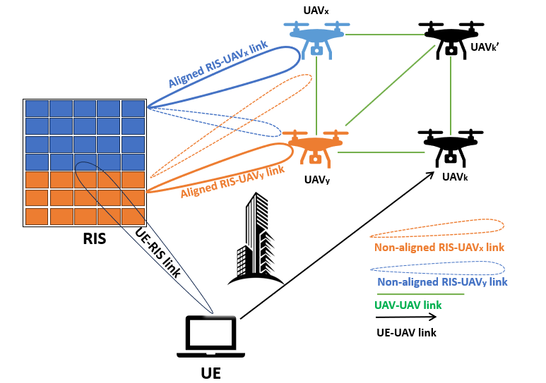
In the depicted scenario of Fig. 1, we consider the setup of two UAVs and , represented by UAVj, , which are blocked and can not communicate directly with the UE and must communicate through the RIS, where UAVx is more reliable than UAVy. Low reliable UAV is the most critical one that causes severe connectivity degradation if it has failed due to low battery and hardware and software issues. In Fig. 1, UAVy is not reliable since it has many connections to the network, thereby could be critical and fail at any time. Therefore, the data of UE should not be solely transmitted to UAVy. Therefore, the RIS can concurrently boost the signal dedicated to the more reliable UAVx and relatively enhance the QoS of UAVy. This process involves designing certain RIS elements’ phases to significantly maximize channel while a few elements’ phases should be configured to align with the channel. The two-UAV setup is considered for analytical tractability and to draw important insights into the RIS partitioning and deployment design.
The number of RIS elements allocated for UAVj is denoted by , where is the RIS allocation factor such that and ensure that the total number of the allocated RIS elements for partitioning is equal to the physically available number of the RIS elements. Furthermore, the reflection coefficient matrix of the RIS is modeled as , where and is the phase shift of the -th element, with , .
II-B Channel Model
The channels between the UE and the UAVs (RIS), between the UAVs and the UAVs, and between the RIS and the UAVs are considered to be quasi-static with flat-fading and presumed to be perfectly-known. To practically model the communication links between the UE and the RIS, between the RIS and the UAVs, and between the UE and the UAVs, we consider the Nakagami fading model that characterizes different fading conditions, i.e., () for severe fading and for nearly line-of-sight (LoS). We represent the small-scale fading coefficient and path-loss for the channel as and , respectively. Likewise, the small-scale fading coefficient and large-scale path-loss for the channel are denoted as and , respectively. Here, and . Therefore, we consider the channel from the UE to UAVj over the -th RIS element as , where denotes the channel coefficient between the UE and the -th RIS element, while is the channel coefficient between the -th RIS element and UAVj; and are the channel amplitudes, while and are the channel phases.
Moreover, for the direct links between the UE and the UAVs, let and denote the small-scale fading coefficient and path-loss for the channel, respectively. For the channel, the signal-to-noise ratio (SNR) is defined as , where is the additive white Gaussian noise (AWGN) variance. A typical UAVk is assumed to be within the transmission range of the UE if , where is the minimum SNR threshold for the UE-UAV communication links.
For simplicity, we only consider the LoS path component for each UAV-UAV link, which is well justified for UAV communications [2, 9]. Thus, the LoS path-loss between UAVk and UAV can be expressed as where is the distance between UAVs and , is the carrier frequency, is the speed of light, and is the distance between UAVk and UAV. The SNR in dB between UAVk and UAV is . UAVk and UAV have a successful connection provided that , where is the minimum SNR threshold for the UAV-UAV communication links.
II-C SNR Formulation
In light of the preceding discussions, the SNR at UAVj, , can be expressed as
| (1) |
where is the Cartesian coordinates of the RIS. Furthermore, due to the available perfect global channel state information (CSI) and using high bit resolution of the RIS element’s phase shifter [15], we consider that a portion of RIS elements is perfectly aligned with cascaded channel, while the rest RIS elements are aligned with channel and not aligned with the channel. Hence, for the sake of analytical tractability, we ignore the impact of non-aligned links from (1)111Although we ignore the impact of non-aligned channels for tractability purposes, we show in Fig. 2 that the impact of non-aligned channels on the SNR performance is negligible..
Moreover, for feasible optimization in this paper, we can represent the RIS elements’ allocation portions to denote the RIS section allocated to the UAVsj, . Hence, in the first summation term in (1) can also be presented as . Additionally and without loss of generality, we rewrite the summation term of as 222Note that real-valued RIS portions may result in non-integer RIS partition allocation. In this case, the RIS allocates some elements for exact portion allocated for UAVs .. We further rewrite as
| (2) |
where is the -element double-Nakagami that is independent and identically distributed (i.i.d.) random variable (RV) with parameters , , , and , i.e., the distribution of the product of two RVs following the Nakagami distribution with the probability density function (PDF) is given in [12].
The total channel gain for cascaded channels in (II-C) can be maximized through the optimization of the reflection matrix . Since RIS’s controller has perfect knowledge of the CSI, it has the capability to determine suitable phase shifts that can effectively nullify the phases of the respective and channels as , [12, 15]. Specifically, for the -th RIS element, given and , the RIS’s controller can perfectly align with and to nullify their effect, which provides the maximum channel gain value of link.
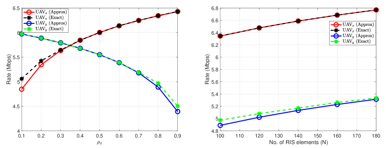
In the remaining of this subsection, we present some numerical results to assess the equivalence of the analytical SNR expressions in (1) and (II-C). All channels are modeled with Nakagami fading distribution. Therefore, we set to emulate the Rayleigh channel for the links, and , and , for and links, respectively. Unless stated otherwise, the following system parameters are considered: dBm, dBm, , dBm. For the purposes of this part, the fixed 3D Cartesian coordinates in meters for the UE are , while UAVx, UAVy, and the RIS are located at , , and , respectively.
Fig. 2 compares exact and approximated rates averaged over Matlab simulations, which are calculated using the SNRs in (1) and (II-C) with bandwidth KHz. For UAVj, the RIS partitions, respectively, are and . We consider phase shift control using phase shift quantization levels similar to [15], where parameter is the bit resolution of the RIS element’s phase shifter. In the literature [15], is considered for high bit resolution (perfect phase shift). From the figure, we notice that approximated rates for the UAVs tightly match the exact rates for most values of and . Overall, these results justify our assumption to ignore the impact of non-aligned channels from the other portions of the RIS. Therefore, in the remaining of this paper, we will use the approximated SNR expression in (II-C).
III Problem Formulation
III-A Network Connectivity
We model the uplink RIS-assisted UAV model using the graph network , where represents the set of vertices associated with the network nodes (UAVs and UE) and represents the edges (links). For a graph edge , , that links two nodes , we have:
| (3) |
Subsequently, the weight vector of these links is defined as , and is given element-wise as
| (4) |
For , let be a vector, where the -th and -th elements in are given by and , respectively, and zero otherwise. Let be the incidence matrix of a graph with the -th column given by . Hence, in an undirected graph , the Laplacian matrix is a matrix, defined as [5]:
| (5) |
where the entries of are given element-wise by
| (6) |
where is the degree of node , which represents the number of its neighboring nodes.
To maximize the connectivity of the uplink RIS-assisted UAV network, we choose a well-known metric, known as the algebraic connectivity [16, 5, 4, 3, 2, 10], denoted as , to measure how well a network is connected. With RIS deployment and partitioning, a new graph is constructed with the same number of nodes and a larger set of edges denoted by with , where is the new edges for the and links. The gain can be realized by computing , where is the resulting Laplacian matrix of the new graph .
In this paper, we measure the reliability of the UAVsj∈{x,y} based on the severity of network connectivity after removing UAVj and its connected edges to other nodes, which is defined as , where is the sub-graph resulting from removing UAVj and all its adjacent edges to other nodes in . Thus, we consider .
III-B Problem Formulation
In this paper, our interest is to unleash the benefits of the RIS to aid the uplink connections of the UE to the blocked UAVs. Following the previous results and discussions suggest, the SNR performance improvement inherently requires the joint optimization of RIS partitioning and location to maximize the link quality between the UE and the UAVs via the RIS while ensuring their QoS constraints. Let be the minimum SNR threshold of via the RIS. The considered optimization problem is formulated as
| (7a) | |||
| (7b) | |||
| (7c) | |||
| (7d) | |||
| (7) | |||
| (7e) | |||
where is the pairwise inequality and is a design parameter that determines the QoS limit set for the least reliable UAVy based on . In P0, and constitute the QoS constraints on the UAVsj∈{x,y}, ensures that the allocated portions does not exceed unity to limit the total number of allocated RIS elements is not higher than the total number of RIS elements. Finally, specifies the domain of optimization variables. The Laplacian matrix depends on the RIS location and partitions, which determine the quality of the new links. To tackle P0 over and , we decompose P0 into two subproblems and solve them iteratively. For given RIS location , we optimize by finding a closed-form solution of the RIS portions, denoted by , that pushes the UAVsj∈{x,y} SNR to its maximum. Then, we exploit the closed-form RIS partitioning solution to find the 3D deployment of the RIS to further maximize .
IV Proposed Solution
Maximizing network connectivity requires optimization over a graph structure, i.e., the selection of UE and UAV nodes and their link quality. Since the nodes (the UE and the UAVsj∈{x,y}) are known and network connectivity is a monotonically increasing function of the added links and their weights [16], we can equivalently maximize the network connectivity by maximizing the SNR of the added new links via the RIS.
IV-A RIS Partitioning Optimization
The first subproblem of the RIS partitioning to maximize the sum SNR of the UAVsj∈{x,y} can be formulated for a given RIS location by using P0 and (II-C) as follows
| (8a) | |||
| (8b) | |||
| (8c) | |||
| (8) | |||
| (8d) | |||
which can be solved by pushing the SNR of the link, corresponding to the most reliable UAV, to its maximum value. In what follows, we provide the closed-form solution for the RIS partitioning.
First, the sum SNR can be maximized by satisfying UAV ’s QoS constraint in with equality while pushing to its maximum subject in . Therefore, we rewrite in (8) using (II-C) as follows
| (9) |
The closed-form solution for can be derived as
| (10) |
Subsequently, the rest of the unused elements should be allocated to UAVx, and therefore, all available RIS elements must be used to reach the maximum SNR of that UAV. Thus, the RIS portion allocated to UAVx is written as
| (11) |
Notice that the solution and are feasible only if the constraints in (8) are satisfied. In general, the RIS partitioning closed-form solution of the two-UAV setup can be generalized to multiple-UAV setup, where is given as
| (12) |
where is any number of blocked UAVs that is greater than one. The solution first needs to find the RIS partitions that satisfy the SNR limit of the least reliable UAV and so on.
IV-B RIS Deployment
The RIS location substantially affects the network connectivity performance as it directly relates to the channel gains and path-loss for the links via the RIS. Therefore, this subsection considers the RIS deployment problem formulated in P2 to maximize the SNR of those links by using the RIS portions derived in the previous subsection:
| (13a) | |||
| (13b) | |||
| (13c) | |||
| (13d) | |||
| (13e) | |||
where . defines the search space range for the coordinates as extending from negative infinity to positive infinity, while the coordinate constraint for is limited to a range between and . We solve P2 by meta-heuristic methods that run a global search of the RIS locations and evaluate the location fitness by the proposed RIS partitioning. In this work, we use the simulated-annealing (SA) method to solve P2.
V Numerical Results
In this section, we present the numerical results for solving , where system parameters are the same as in Section II-C for UAVs in the network. Unless otherwise stated, , , and , which means that the QoS for link is enforced to be % of the QoS for link. In these simulations, we utilize the 3GPP Urban Micro (UMi) model [12] at a carrier frequency of GHz to compute the large-scale path loss values for UE-UAVs links, while similar to [10], we use and for and links, respectively, where denotes the path loss at the reference distance m and is the corresponding distance.
Fig. 3 compares the network connectivity of the proposed scheme versus the number of UAVs with the following benchmark scenarios. 1) One Link: All RIS elements are allocated to beamform the UE’s signal to a predefined UAVx; 2) One Link (Optimal): All RIS elements are allocated to beamform the UE’s signal to the selected optimal UAV, which is found via linear search; 3) Proposed (Random RIS Location): It is the proposed scheme but with a fixed RIS location; 4) RIS-Free Network; 5) RIS-Free Network (No Direct UE-UAV Link). Notice that the one link schemes are special cases of the proposed (optimal) and proposed schemes, where RIS elements are not allocated to align with UAVy, thus the QoS constraint in is satisfied. The results show that the proposed (optimal) scenario leads to significant connectivity performance with at . This is due to the fact that the proposed (optimal) scenario exploites the full benefit of RIS partitioning and deployment to create two links while finding the desired two blocked UAVs that maximizes the connectivity; finding the desired two blocked UAVs is via linear search of all the UAV combinations. For this reason, the proposed (optimal) is better than the proposed, where we predefined UAVx and UAVy in advance. On the other hand, RIS-free network scenario provides the worst connectivity. Furthermore, we can notice that the proposed (random RIS location) scenario slightly decreases the connectivity. For example, when is , the connectivity of proposed (random RIS location) is , while that for proposed is . Finally, the RIS-free network (no direct UE-UAV link) scheme has zero connectivity since the network graph is not one component. This showcases the leverage of deploying the RIS for maximizing connectivity of UAV networks not to only support UE communication, but also to connect the UE to the network when the direct UE-UAV link is unavailable.
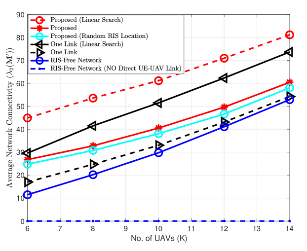
Fig. 4 compares the network connectivity versus RIS elements . It is noticed that the increase in the number of RIS elements increases connectivity, since RIS with more elements can boost up the quality of the new and links. Specifically, since our RIS partitioning closed-form solution calculates that satisfies the minimum QoS of link, the remaining RIS elements, which increases as increases, are configured for link to maximize its SNR to the maximum value. Thus, this increases the network connectivity. RIS-free scheme is maintained fixed since it has nothing to do with changing the RIS elements.
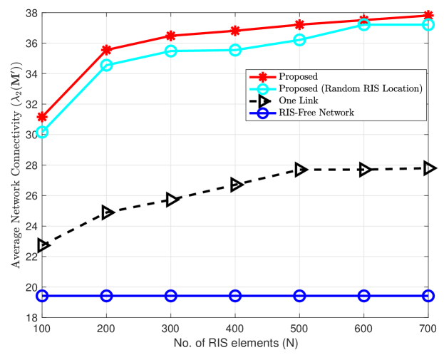
Fig. 5(a) demonstrates the rate performance, which is calculated as , versus for and dB. It is noticed that the increase in leads to increase the QoS threshold of the link, which needs more RIS elements to satisfy it, thus decreases the SNR for link, as expected. For example, when , RIS portion for case is about to satisfy SNR of , while RIS portion for case is about to satisfy the maximum SNR of the link. Accordingly, the rate of the link is Mbps, while for the link is Mbps. This decrease in UAVx rate is because more RIS elements are required to satisfy the increasing QoS requirement for the link. As a result, fewer RIS elements are left to boost up the signal of link.
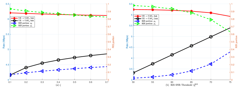
Fig. 5(b) plots the rate performance versus for and . In terms of RIS allocations, we observe that the increase of the added links QoS via increasing leads to significant increase in the number of RIS elements needed to satisfy the minimum QoS requirement for link. For example, when increases from dB to dB, jumps from (around elements) to ( elements), and almost of the RIS elements is partitioned to align with UAVy when dB. Thus, the rate of link increases and the rate of link decreases since a few RIS elements are left to be aligned with UAVx.
VI conclusion
In this paper, we have studied the UAV connectivity by exploiting RIS partitioning and deployment to improve connectivity of UAV networks, supporting UE-UAV communication or connecting the UE to the network when direct links are unavailable. We have developed a closed-form solution for RIS partitioning, while simulated-annealing is used for RIS deployment. Simulation results have shown that with the introduction of RIS partitioning, substantially higher achievable connectivity and SNR can be obtained compared to its RIS-free and one link counterpart.
References
- [1] S. Zhang, Y. Zeng, and R. Zhang, “Cellular-enabled UAV communication: A connectivity-constrained trajectory optimization perspective,” IEEE Trans. Commun., vol. 67, no. 3, pp. 2580-2604, Mar. 2019.
- [2] M. A. Abdel-Malek, A. S. Ibrahim, and M. Mokhtar, “Optimum UAV positioning for better coverage-connectivity trade-off,” 2017 IEEE 28th Annual Intern. Symposium on Personal, Indoor, and Mobile Radio Commun. (PIMRC), Montreal, QC, Canada, 2017, pp. 1-5.
- [3] A. S. Ibrahim, K. G. Seddik, and K. J. R. Liu, “Connectivity-aware network maintenance and repair via relays deployment,” in IEEE Trans. on Wireless Commun., vol. 8, no. 1, pp. 356-366, Jan. 2009.
- [4] A. Albanese, P. Mursia, V. Sciancalepore and X. Costa-Pérez, “PAPIR: Practical RIS-aided localization via statistical user information,” 2021 IEEE 22nd Inter. Workshop on Signal Processing Advances in Wireless Commun. (SPAWC), Lucca, Italy, 2021, pp. 531-535.
- [5] C. Pandana and K. J. R. Liu, “Robust connectivity-aware energy-efficient routing for wireless sensor networks,” in IEEE Trans. on Wireless Commun., vol. 7, no. 10, pp. 3904-3916, Oct. 2008.
- [6] M. Ammous and S. Valaee, “Cooperative positioning with the aid of reconfigurable intelligent surfaces and zero access points,” 2022 IEEE 96th Vehicular Tech. Conf. (VTC2022-Fall), London, United Kingdom, 2022, pp. 1-5.
- [7] M. Javad-Kalbasi, M. Saif, and S. Valaee, “Energy efficient communications in RIS-assisted UAV networks based on genetic algorithm”, 2023 IEEE Global Commun. Conference, Kuala Lumpur, Malaysia, 2023, pp. 5901-5906.
- [8] M. Obeed and A. Chaaban, “Joint beamforming design for multiuser MISO downlink aided by a reconfigurable intelligent surface and a relay,” in IEEE Trans. on Wireless Commun., vol. 21, no. 10, pp. 8216-8229, Oct. 2022.
- [9] Z. Wei et al., “Sum-rate maximization for IRS-assisted UAV OFDMA communication systems,” in IEEE Trans. on Wireless Commun., vol. 20, no. 4, pp. 2530-2550, Apr. 2021.
- [10] M. Saif, M. Javad-Kalbasi, and S. Valaee, “Maximizing network connectivity for UAV communications via reconfigurable intelligent surfaces”, 2023 IEEE Global Commun. Conference, Kuala Lumpur, Malaysia, 2023, pp. 6395-6400.
- [11] A. Parchekani and S. Valaee, “Reconfigurable intelligent surface assisted sensing and localization using the Swendsen-Wang and evolutionary algorithms,” 2023 IEEE 98th Vehicular Technology Conf. (VTC2023-Fall), Hong Kong, Hong Kong, 2023, pp. 1-6.
- [12] S. Arzykulov, A. Celik, G. Nauryzbayev, and A. M. Eltawil, “Analyzing and minimizing secrecy outage in aerial RIS-enhanced physical layer security,” 2023 IEEE Globecom Workshops (GC Wkshps), Kuala Lumpur, Malaysia, 2023, pp. 479-484.
- [13] H. Chen et al., “RISs and sidelink communications in smart cities: The key to seamless localization and sensing,” in IEEE Communications Magazine, vol. 61, no. 8, pp. 140-146, Aug. 2023.
- [14] K. Weinberger, R.-J. Reifert, A. Sezgin, and E. Basar, “RIS-enhanced resilience in cell-free MIMO,” WSA & SCC 2023; 26th International ITG Workshop on Smart Antennas and 13th Conference on Systems, Communications, and Coding, Braunschweig, Germany, 2023, pp. 1-6.
- [15] S. Arzykulov, G. Nauryzbayev, A. Celik, and A. M. Eltawil, “RIS-assisted full-duplex relay systems,” IEEE Systems Journal, vol. 16, no. 4, pp. 5729–5740, 2022.
- [16] M. Fiedler, “Algebraic connectivity of graphs,” Czechoslovak Mathe- matical J., vol. 23, pp. 298-305, 1973.